Resource Allocation in a High Clock Rate Microprocessor Michael
Upton, Thomas Huff, Trevor Mudge & Richard Brown
Department
of Electrical
Engineering
University email:
[email protected].
Science
200ns, or 1200ns. Access times in current high-end workstations such as the HP 9000/735 have decreased to around 150ns, but this may be as many as 20 cycles. Over the past decade, main memory speeds have improved by only a factor of 10, while processor speeds have increased by a factor of 100. As cycle times continue to improve, the primary cache miss penalties will rise from their current levels to as many as 100 clock cycles. The increasing performance difference between processor and memory speeds, combined with large but finite transistor budgets, presents many interesting trade-offs for computer architects. Given a limited resource budget, the designer must choose the relocation of resources needed to optimize performance. With a limited chip ar+ resources could be devoted to increasing the onchip cache size, adding other memory structures, or adding execution units. At high clock rates, additional execution units may be starved for data because of long memory latencies. This paper examines the resource allocation in superscalar multi-chip microprocessor design. The architecture is briefly described and the goals for the design are explained. The performance of three processor configurations is evahrated using tracedriven simulation. A cost model is used to estimate the resources required to build processors with varying sizes of on-chip memories in both single and dual issue versions. Recommendations are then made to increase the effectiveness of each of the models.
Abstract This paper discusses the design of a high clock rate (300MHz) processoc The architecture is described, and the goals for the design are explained. The perjiormance of three processor models is evaluated using trace -dn”ven simulation. A cost model is used to estimate the resources required to build processors with varying sizes of on-chip memories, in both single and dual issue models. Recommendations are then made to increase the effectiveness of each of the models. Keywords: Pipelining, decoupled architecture, prefetching, non-blocking cache, resource allocation, superscala~ jloating point latencies.
1
and Computer
of Michigan edul, thuff (ikecs.umich.edu
Introduction
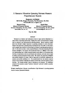
This paper describes the decisions made in the design of an experimental high-performance general purpose processor suitable for a workstation or a high end PC system. The goals include integer performance of 200 SPECint and floating point performance of 300 SPECfp, with power dissipation such that the system can be air cooled. Fast switching speeds led us to choose Gallium Arsenide Direct Coupled FET Logic (DCFL) combined with MCM technology to build a compact multiple-chip processing element. The MIPS R3000 ISA was chosen because it is a relatively clean architecture with good architectural development tools. Figure 1 shows single chip microprocessor clock frequencies for processors presented at the International Solid State Circuit Conference. Over the past 10 years the frequency of microprocessors has increased at a rate of about 40% per year. The fastest chip introduced each year is usually at least twice as fast as the slowest chip for that year, and the gap has been widening. The fastest clock rate processors do not necessarily have the highest system level performance, but the overall trend reflected in this data strongly suggests that processor clock frequencies will continue to increase. In contrast, the rate of increase in main memory speed has been lower than that of CPUS. The core-based main memory access time of the CDC6600 was 1000ns [15]. Main memory operations on the 1978-vintage VAX 11-780 required 6 cycles of
2
System
Overview
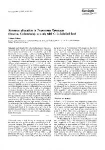
The Aurora III microprocessor is the culmination of three years of research on implementing pipelined microprocessors using GaAs technology. A block diagram of the Aurora III system is shown in Figure 2. The system is composed of four custom GaAs chips: three logic chips and a 32 K-bit SRAM used for building a 64 K-byte data cache. The logic chips are the Floating Point Unit (FPU), Integer Processing Unit (IPU) and Memory Management Unit (MMU). This partitioning is similar to the SGI R8000 TFP processor [6]. For the system level performance of our GaAs chipset to be competitive with that of contemporary CMOS processors the GaAs system must overcome with increased clock speed the CMOS advantage of much higher integration density, which allows increased parallelism and larger caches. We have explored processor microarchitectures that allow parallel instruction issue without adversely impacting system cycle time. The IPU consists of five functional modules that operate semiautonomously to fetch, decode, execute and retire instructions.
Permission to copy without fee all or part of this material is granted provided that the copies are not made or distributed for direct commercial advantage, the ACM copyright notice and the
title of the publication and its date appear, and notice is given that copying is by permission of the Association of Computing Machinery. To copy otherwise, or to republish, requires a fee and/or specific permission. ASPLOS W 10/94 San Jose, California USA @ 1994 ACM 0-89791 -660-3/94/0010..$3.50
TM work was supported by the Denfese Advanced Research Projects Agency under Contract Number DAAL03-90-C-O028.
98
J
NEC
RiSC
BIPSO● Hitachi . Alpha ● DEC VAX
Intel 386
TI GaAa .
ti@
1oo-
●
NEC
Pentiurn2
/
IBM 803
● Mitubishi Cisc
RPM40 ● GE FPU
lo-
MIPS-X ●
AIT FPU ● ● NIT FPU
; I
HP PA
h
HP PA
DEC FPU u Intel 8S0 .
.-c
UMicJ Ga Y
HP PA ●
DEC
CVAX
● HP PA
/
/ >DEC
VVAX
● NEC
Dsp
● f+pFplJ
DEC VAX
RISC2
1 1
84
I
[
I
I
I
I
1
I
I
85
86
87
88
89
90
91
92
93
9
Year Figure 1: Microprocessor 3nglectip microprwessor clock frquencies forprocessors pre~nted ahown represents about a 40% increase per year m frequency.
atthe
Clock Frequencies last eleven international
Solid State Circuit Conferences.
The line
the bus. Using a Rarnbus-like signaling scheme [10], the clock is generated on-chip and sent with the data to minimize clock skew. Data is transferred on both edges of the clock to maximize IO bandwidth. Instruction Fetch Unit The IFU fetches instructions and maintaining the state of the on-chip Instmction Cache. Icache misses are detected in the IFU, and the missing instructions are requested from the MMU via the BIU. The front of the IEU pipcline stalls until the needed instructions arrive, but the LSU continues to process pending data cache misses, and the reorder buffer continues to retire completed instructions. An on-chip instruction cache was required to support a twoinstmction-per-cycle issue rate. Too few IO pins were available to fetch 64 instruction bits each cycle. Thexe are few restrictions on which instructions can issue together. Other than true instruction dependencies, in which an instruction uses the result of the immediately preceding instruction, the primary issue constraint is that only a single memory access instruction can be executed in a given cycle.
The IPU is similar to the IBM-Motorola PowerPC 603 and 604 processors [2] inthatit includes aBus Interface Unit (BIU), an Integer Execution Unit (IEU), an Instruction Fetch Unit (IFU), and a Load Store Unit (LSU). In addition to these the IPU has a dedicated Ilefetch Unit (PFU) for data and instructions. Bus Interface Unit The Aurora III memory system is designed to provide a large memory bandwidth from main memory through the MMU to the primary caches. Sustained transfer rates of over 1.5 G-bytes per second have been demonstrated in the BIU performance model for typical workloads [14]. Long memory latencies require high bandwidth to support prefetching and nonblocking caches [9]. The asynchronous BIU interface allows external communication and internal computation to proteed independently. The IPU is connected to the MMU by a bidirectional 32-bit bus. To tolerate the transaction latency in the system, multiple pending requests are buffered in separate transmit and receive queues. A split-transaction collision-based protocol allows either the IPU or MMU to immediately send data without arbitrating for
99
t 10 Bus I MM
Instruction Memory
MMU
W
‘Ioatinq Point Unit
Data Memory
IQ
9
Bus Interfac
Memory Management Jnit
n
~n.I Interface
Score Board
E=TiF-=-g$ ----------- ‘Qw9Q T6i3 La ‘ ‘“-”--”N--’-L G!?
Prefetch
‘n” Instruction Fetch
Unit
,
1
f
PreDecode
lCache
Next Acfdr
f I I I 1 I f 1 f
I
Write Cache
‘
DA!
---
f - I
---
,~
Pioelined Ekernal Primary Data Cache
b-------
-------
-------
-----d
-------
Integer Processor Unit Figure 2: Processor
Block Diagram
cates whether the instruction pair includes a control flow instruction, such as a jump or branch. The MIPS ISA prohibits a branch instructions in a branch delay slot, so there will be a maximum of one control flow instruction in each pair. If the instruction pair contains a control flow instruction, the NEXT field contains the cache index of the target instruction. This branch folding [3] reduces the critical path for a dual issue machine by eliminating
To speed the instruction issue logic, instructions are predicoded before being inserted into the instruction cache. Figure 3 shows the arrangement of a decoded instruction. All instructions are grouped into pairs, with the EVEN instruction occupying the lower of two consecutive addresses, and the ODD occupying the next sequential address. The DI bit indicates whether an instruction pair dependency prohibits dual issue. The CONT field indi-
100
32 bits
1 bit
32 bit
Figure 3 Decoded
Instruction
5 bits
2.3
7 bits
Instruction
Execution
Cache Fields
Unit
The key elements of the IEU are the 32x32 integer register file and two execution pipelines, which consist of art ALU and a sixentry reorder buffer [13]. A register file scoreboard [15] detects instruction dependencies and stalls execution until the needed operands are ready. To achieve high system clock frequencies, both the area and the number of logic levels needed to implement a logic function must be minimized. Among the main contributors to die area in our previous GaAs microprocessors were the pipeline latches. These latches increase the operating frequency by breaking long operations into smailer stages, but they also increase the layout area. In addition, every pipeline stage after the ALU, such as load delay slots, requires a forwarding path back to the ALU inputs. The state latches and forwarding network for one of our earlier prototypes account for 50% of the execution pipeline area[16]. One way to minimize the area penalty for state latches is to have a short execution pipeline. LAe the Motorola 88K [1], we have adopted variable length pipelines, reducing the length of the integer pipelines to four cycles. Memory instructions require an additional two or three cycles to produce their results. Virtuat addresses are genetated in either of two identical integer ALUs. The address and any store data are transmitted to the LSU and data cache in one cycle. Forwarding paths allow the ALU output and the reorder buffer contents to be used as inputs for the next instruction, avoiding pipeline bubbles.
2.2
Prefetch
Unit
To simplify the execution unit pipeliies, a separate function unit processes all memory operations. The IEU computes the memory address in its ALU and checks for any illegal address exceptions. The address and store data for store instructions are passed to the LSU. The IEU rdso provides a 3-bh tag value indicating the reorder buffer destination slot. To accommodate a data cache large enough to achieve good system-level performance, the cache RAMs must be extem-d to the CPU. The system supports external caches of 16 K-, 32 K-, and 64 K-bytes. The external data cache is direct-mapped, pipelined, and has a three-cycle latency. A new access can be initiated each cycle. The cache is accessed using two unidirectional 64-bit data busses and a 14 bit address bus. To amortize the long primary cache miss penalty, the processor supports multiple outstanding cache misses. As long as the target register of a load instruction is not referenced, other instructions can issue, execute and complete, leaving their results in the reorder buffer. Even more importantly, the access delay of multiple cache misses can be overlapped. A number of Mk.s Service Holding Registers (MSHRS) maintain the state of pending cache misses. An MSHR is reserved for each memory instruction active in the LSU pipeline, and if no MSHRS are available, the processor stalls until one is free. A machine with only one MSHR cannot overlap memory operations, and must process each load or store sequentially. Write Cache The LSU contains a 32-word coalescing write buffer called the Write Cache [8]. The 32 data words are organized as four cache lines of eight words per line. The four lines are fully associative. The write cache groups multiple memory references into a single BIU transaction. Memory write behavior has two characteristics that are effectively exploited by the write cache. Multiple writes will often occur to the same address, as would happen in an inner loop during the updating of the loop index. After the first write to the index address, subsequent writes would hit in the write cache, replacing the previous value. Thus fewer BIU transactions are required to keep the memory system coherent. The second memory access pattern that benefits from a write cache is vector-like operations such as memory copies or floating-point intensive code. In these operations, each entry in the write cache is written in succession, but only one BIU transaction is needed to retire the eight words. Write Validation Because the MMU is off-chip, the processor cannot retire store instructions until it is known that the address accessed will not cause a memory fault. Receiving a response from the MMU requires many cycles, so simply querying the MMU about each write address is an unacceptable solution. Instead the write cache divides the address tags into page and offset fields. If the page field of the current write address matches any of the valid page fields contained in the write cache, then a write or access fault is not possible. In effect, the write cache operates as a four entry micro-TLB. Floating Point Support ~ this architecture, floating point memory instructions transfer data directly between memory and the integer and floating point register files. Unlike integer stores, floating point store data is not immediately ready at the time the instruction is transferred to the LSU. Thus, write cache eviction and data cache writeback must wait for the data. This adds a certain degree of complexity to the synchronization of the floating point data and the cache line within the write cache. In order to meet package pin constraints, all floating point instruction and data transfers occur via the input and output busses of the primary data cache.
the branch pipeline bubble. The target of the branch can be fetched on the next cycle, without needing to compute a target address from the addtess of the branch instruction.
2.1
Load-Store
Unit
A set of hardware prefetch buffers is included to minimize long memory system latencies caused by the fast clock rate and multiple chip partitioning. The prefetch buffers predict future memory requests and bring the data on chip before it is referenced by the IPU. Jouppi proposed the addition of a small set of associative prefetch buffers, called stream buffers, to fetch sequential lines ahead of the curtent program counter [7]. The stream buffer consists of a tag register, a tag comparator, a set of status bits and a number of prefetch cache lines for instructions and data. If a memory reference misses in the primary cache, the stream buffers are checked to see whether the required data have already been requested. Jouppi showed that stream buffers can be highly effective for small caches, reducing the cache miss rate by up to half. Since we have limited space for on-chip caches, these are an ideal solution. On each instruction or data cache miss, a stream buffer is allocated and initialized to fetch the next sequential line. This buffer initially fetches only a single line. If a subsequent request hks in a prefetch buffer, additional scqucmtial lines are fetched until the buffer is filled.
101
2.4
The Branch perscalar
Delay Slot Problem
and the exception tion can occur.
in Su-
Architectures
Floating
3.1
Overview
Point
Unit
an excep-
4
Architectural
4.1
Benchmarks
Evaluation
Design
Architectural performance was evaluated using the integer and floating point Spec92 benchmarks. Time constraints imposed by other phases of the design process limited the length of the benchmarks that could be run. The integer benchmarks used the “small test” input file, and the floating point benchmarks were limited to their first 90 million cycles. In all, about 176 million instructions were run from the integer suite, and about 810 million from the floating point suite. All benchmarks were compiled using GCC with no additional code rescheduling.
Limited integration levels in GaAs constrain the amount of functionality that can be placed on a single chip. Gne obvious partitioning, shown in Figure 2, includes separate FPU, IPU, and data cache chips. Floating point operations tend to have longer latencies than integer instructions, which are made worse when interchip communication is necessary. To support double precision numbers, floating point datapaths are wider than their integer counterparts. The time needed to drive control signals across these wide datapaths places an upper limit on clock frequency and results in different maximum operating frequencies for the ET-J and FPU. The resources of the IPU and FPU can be used more efficiently if the architecture decouples their operation; one way to achieve this is through the use of instruction and data queues. The use of an instruction queue instead of a single entry instruction buffer allows the IPU to slip ahead of the FPU during program execution. Instead of stalling for FPU data dependencies, the IPU is able to transfer floating point instructions and continue execution. The IPU will be forced to stall due to the FPU only when the queue becomes full or when it has to wait for the result of an FPU operation. The use of an instruction queue does impact the precise handling of exceptions, since the IPU may be many instructions ahead by the time a floating point exception is detected. Gne solution involves having both a precise execution mode and a higher performance mode. For the former, instmctions are not transferred to the FPU unless they are guaranteed never to cause an exception; examination of operand exponents
Model
whether
The use of an instruction queue necessitates a corresponding load queue to store load data prior to its being written into the floating point register file. However, the depth of W queue does not need to be as large as that of the instruction queue. Similarly, a store queue is used to hold the results of floating point store and move-to-IPU instructions. The FIT-J also includes a 32x64 entry register file, reorder buffer, scoreboard, and separate functional units for addition, multiplication, division and conversion. Up to two floating-point instructions from the queue can issue per cycle, to any two of the functional units. Two independent busses are available to write results from the various functional units to the reorder buffer. The add unit is pipelined with a latency of three cycles. The multiply and divide units are iterative and can produce a result in five and 19 cycles, respectively. The conversion unit has a latency of two cycles and performs conversions between single, double, and integer formats. Each functional unit supports the IEEE-754 specification for rounding modes and exceptions.
Although modem RISC machines are designed to have few implementation artifacts, a notable exception is the architectural branch delay slot. The branch delay slot was added to rdlow the processor to execute an instruction while the instruction at the branch target was being fetched, avoiding bubbles in the pipeline. Because architectural branch delay slots significantly complicate the design of superscalar machines, they have been eliminated from more recent architectures such as the DEC Alpha [4]. The branch delay slot causes problems for a superscalar machine in many of the same ways that variable length instructions cause problems for CISC machines. The delay slot may lie on the next cache line. If this line causes a cache miss, the delay slot address and the target address must both be saved until the cache line for the delay slot is fetched. The delay slot must then be issued, and instruction fetching must resume at the target of the branch. Even worse problems occur when the branch and the delay slot span virturd memory page boundaries.
3
flags can be used to predict
I Cache Size
4.2
Architectural
alternatives
Three machine models, referred to as the large, baseline and smrdl models, were chosen to evaluate the effects of resource relocation and memory latency. The hardware resources allocated to each are listed in Table 1. Each of the three models is evaluated with one or two execution pipes, and with secondary memory system average Iatencies of 17 and 35 cycles, corresponding to medium and fast clock rates. Thus, results for 12 configurations are reported. The register bit equivalent (RBE) model of Mulder [11] was used to evaluate the implementation cost in chip area of the different configurations. The RBE model provides a normalized measure for the area cost of diffe~nt microarchitectural components. For our machines the RBE is the area required to implement a 1bit static latch. For GSAS DCFL, one static latch requires about 16
D Cache Size
Write Cache Size
Reorder Buffer
Prefetch
Entries
Buffers
MSHR Entries
Small
1 Kbyte
16 Kbyte
2 lines
2
2
1
Baseline
2 Kbyte
32 Kbyte
4 lines
6
4
2
Large
4 Kbyte
64 Kbyte
6 lines
6
8
4
Table 1: The Three Machine
Models
and their Associated
102
Resources
IPU Element
Cost in RBE
1 Kbyte Cache Block
FPU Element
Cost in RBE 4,000
8,000
1 Data Resource Block (RF, SB)
2 Kbyte Cache Block
12,000
1 Queue Entry (instructiorVdata)
4 Kbyte Cache Block
20,000
1 Add Unit (l-5 cycles)
5,000-1,250
320
1 Multiply Unit (l-5 cycles)
6,875-2,500
1 Prefetch Line
320
1 Divtde Unit (10-30 cycles)
1 Reorder Buffer Entry
200
1 Conversion Unit (1-5 cycles)
1 Write Cache Line
50/80
2,500-625 2,500-1,250
50
1 MSHR Entry 1 Integer Exacution Pipeline
8192
Table 2: Processor
Element
Cost in RBE Units increases in area will in [12].
transistors and corresponds to an area of about 3600 square microns. Static RAM elements are denser, with a single blt requiring an area equal to 0.5 RBE. However, RAM blocks have additional overhead devoted to decoding and sensing. This overhead is a significant fraction of total area for small RAM blocks. The cost of each microarehitectural element is listed in Table 2. These figures are based on layout obtained during chip design. In addition to memory elements, the cost of an execution pipeline is also estimated. An important assumption in this analysis is that the cost of interconnecting microarchitectural elements is an overhead. that scales with the sum of their areas. The cost of data cache is not included in our analysis beeause limits on die size placed the data cache in chips separate from the IPU and FPU. A more comprehensive cost analysis would optimize a system consisting of the IPU, FPU and data cache chips on the MCM in a way analogous to the intra-chip design problems considered in this paper. Finally, it is important to note that
5
Study
slow the clock cycle. This issue is addressed
Results
The size and quantity of both on-chip memory structures and execution pipelines were varied to study the trade-offs between memory structures and execution logic. The Cycles Per Instruction (CPI) for each benchmark were measured, and can be compared to the implementation cost to evaluate the effectiveness of various memory and pipeline structures. The base model instruction cache hit rate is 96.570 and data cache hit rate is 95.4%; these numbers agree with those published in [5].
6– 5.55-
5-
•l dual issue ■ single issue
4.54$
4.54-
small •1
3.5–
g
1’ ❑ dual issue
1
■ single issue
3.53-
32.5-
2.5large
2-
21.5-
1.5. 1
small
baseline
❑
I
I
I
I
I
10000
20000
30000
40000
50000
10000
20000
30000
40000
50000
RBE
RBE 17 cycle latency
35 cycle latency
Figure 4: Dual and Single Issue Performance Performance vs. cost in RBEs is shown for systems having17 cycle latency and 35 cycle Iatencies. In each graph, the costs of 6 systems are shown. Three are single issue and three are dual issue. The vertical Imes with aquere caps show the range of CPI for each configuration. The upper cap is the maximum CPI, the lower cap is the minimum CPI, and the line is the average CPI.
103
model
espresso
compress
56,26
50.79
94.69
50.73
45.97
56.89
baeelme
61.02
45.33
88.34
53.13
49.01
57.75
large
57.33
40.56
51.41
53.75
48.05
56.10
integer
espresso
model
lPrefetch
Hit Rate Percentage
eqntott
Ii
compress
Sc
7.06
9.80
2.65
6.33
22.34
7.84
baseline
8.95
14.41
2.29
13.13
27.42
8.63
large
7.82
14.57
1.53
17.16
30.00
10.02
Model
Performance
integer
DPrefetch
Hit Rate Percentage the dual and single issue machines have similar cost-performance CPI improvement curves; the dual issue model achieves a 9.!)70 over the single issue model.
Evaluation
We first examine the performance of each of the three models. Figure 4 shows the results for dual and single issue for the 3 baseline models with average secondary latencies of 17 and 35 cycles. For each graph the cost difference between the two curves is caused by the addition of a second execution pipeline, which has a cost of 8192 ~Es. With 17-cycle latencies, the addition of the second pipe results in higher performance with the baseline and large models. The single issue base model has a similar cost and much better performance than the dual issue small model. The large model with dual issue achieves the best performance by 12.7Y0, but with a hardware cost increase of 20.4%. With 35-cycle secondary latencies,
5.2
Instruction
and Data Prefetching
Table 3 and Table 4 show the prefetch buffer hit rates for the instruction and data streams. A prefetch hit occurs if the data misses in the primary cache and hits in one of the prefetch stream buffers. Average hit rates for the integer SPEC benchmarks are 58% for the instruction stream and about 12% for the data stream. Floating-point prcfetch data hit rates average 14.4% for the base
6 5.5
5.5
❑ dual issue ❑ dual issue - no prefetch
~
❑ dual issue - no prefetch r
4m
E 3.5– C) 3-
\
2.5-
2.5-
large
m
2-
2-
1 10000
small
51
small
4 K 3m5_ u 3-
1.5-
❑ dual issue
4.5-
4.5 4
gcc
small
Table4:
5
gcc
Sc
small
Table3
5.1
eqntott
Ii
baseline I 20000
❑
I 30000 RBE
1.54
•1
❑
I 40000
1 5000C
10000
20000
17 cycle latency
30000 RBE
40000
50000
35 cycle latency Figure 5: Effects of Prefetch
Removal
Performance in CPI vs. cost in RBEs is shown for systems having 17 and 35 cycle Iatencies. In each graph, the costs of 8 systems are shown. All are dual issue. The vertical ines with square caps show the range of CPI for each configuration. Filled cape indicate no prefetch and hollow caps prefetch. The average CPIS for the three systeme with prefetch are connected by a hne. The average CPI for the three without prefetch are also connected by a line.
104
•1
34
LSU stall due to LSU busy RB stall due to reorder buffer full
2.5
~tDll dueto,Oad-use
Ez
interlook
,&l\u;&instructio.
Single-17
Single-35
Dual-35
Dual-17
Figure 6: Break Down of Stall Penaltiea
5.4
model, but the peak hit rate on some of the benchmarks is as high z 60T0. Figure 5 shows the effects of removing the prefetch buffers from each of the dual issue models. Prefetching is of little benefit in the small model for a number of reasons. There are only two buffers in the small model, which leads to thrashing between instruction and data references. In addition, the cache miss rates are high, leaving little spare bandwidth for prefetching. Prefetching is much more successful in the base model, resulting in an average improvement of 1170 in the case of 17-cycle latency. Prefetching helps even more in the case of 35-cycle latency, improving performance for the base model by 19%. The large model also sees a significant improvemen~ 11% for the 17cycle latency and 17% for the 35-cycle latency. In addhion to the average performance, prefetching substantially improves worst case performance, reducing the CPI for the short latency cases in our study by 25% and in the long latency case by 35%. ‘l%e cost of adding prefetch buffers is fairly smrdl; for the baseline configuration, the prefetch buffers are only 20% of the instruction cache size.
5.3
Execution
Degree of Non-blocking
Data Cache
One of the largest contributors to high performance is the ability to support multiple outstanding load instructions simultaneously. The number of outstanding data cache misses is set by the number of MSHR registers. Figure 7 shows the effect of changing the number of possible outstardhtg memory references for the different cache models. The small model shows a dramatic performance increase when additional MSHR registers are allowed, and the base model shows a small improvement when adding an MSHR. The large model show some performance decrease when the number of MSHR registers is reduced. from four. All models get highest performance when 4 MSHR entries are available.
5.5
Write
Cache Size
Table 5 gives hit-rate statistics for the on-chip write cache of the different models. The write cache size varies from two lines in the small model to eight lines in the large model. The hit rate includes both load and store data accesses. The write cache has a surprisingly high hit rate, even for the small model. This high hit rate helps to reduce significantly the write traffic off chip. The number of store transactions is reduced to 44% of the number of store instructions for the small case, to 30% for the base model and to only 22% for the large model. This is more than a two-fold reduction in write traffic for the small model and nearly a five-fold reduction for the large model.
Unit Stall Distribution
The IPU has 4 major stall conditions: instruction cache stall while waiting for instructions, load stall when the result of a load instruction is referenced before it has been returned by the LSU, Reorder Buffer full stall, and LSU stall when the LSU is fu~ or is using the data busses to fill the cache. Figure 6 shows the CPI penalty contributed by each of these stall conditions. Except for the small model case, most stalls are caused by
5.6
instruction misses and data cache accesses. In the small model, most cycles are spent waiting for data from the LSU. In the base and large models, performance is not very sensitive to the size of the IPU reorder buffer because the processor often stalls when it references the result of a load instruction before the reorder buffer fills. In the large model, the small percentage of LSU-Busy strolls indicates that most of the data hits in the cache, the large percentage of Load stalls is caused by the three-cycle latency of the pipeIitted data cache.
Analysis of Integer mendations
Data and Recom-
Figure 8 presents all of the simulation data points for the latency-17 data sets for the espresso benchmark. The other benchmarks and latencies give similar performance curves.This graph demonstrates the trade-offs between cost and performance for our machine model. There are three points of note: first, the points labeled A rdl have only a single MSHR and lie well above other
105
model
espresso
Ii
eqntott
compress
Sc
gcc
small
29.22
35.97
31.64
37.82
46.61
42.02
baseline
37.17
49.17
46.34
46.29
52.53
54.93
large
43.73
60.52
60.03
59.67
59.56
63.17
Table 5: Integer Write Cache Hit Rate Percentage
5.7
configurations of equivalent cases, showing the negative impact of blocking caches. The points labeled B correspond to the large model. A performance plateau exists here that yields little gain in
of Floating
Point Resources
As with the IPU, the FPU has a large design space to consider when allocating resources. The options include the number of entries for the instruction, load, and store queues, the size and organization of the reorder buffer and register tie, and the complexity of the floating point functional units. More sophisticated algorithms can be used by functional units to reduce latencies, and
performance even if significant additional cost is expended. The benefits of prefetching are demonstrated by comparing points C and D. They differ only in that D adds prefetching. In general, the small model shows a large performance increase with additional resources, the base model shows a small increase, and the large model shows little increase. The previous data suggest some obvious changes to our baseline machines. All models benefit from increased MSHR entries, because the cost is low, adding MSHR entries provides price-performance benefit. A write cache larger than in the baseline model has little performance benefit. In addition, the prefetch performance of the large model is no better than that of the baseline model. The point labeled Eon the graph suggest reducing the resources for the Iarge model to a 4 Kbyte Icache, a 4-entry write cache, a 6-entry reorder buffer and 4 MSHR entries. Dual issue is reasonable only if supported by sufficient memory resources and becomes less attractive as memoxy latency increases.
pipeiining can be used to reduce critical paths, ail at the experw of adding more transistors. One must determine how to use the available resources most effectively. Dual-issue of floating point instructions adds several issue constraints to that for integer instructions. The usefulness of this feature is dependent on the amount of parallelism in the floating-point workload.
5.8
Floating
Point Issue Policy
Two issue policies were investigated: 1) in-order issue with inorder completion of instructions, and 2) in-order issue with out-of order completion of instructions. The former approach does not allow multiple issue of instructions or instructions active in multiple functional units. Single issue and dual issue arc both possible for the latter policy. Floating point durd issue is constrained by
6
61 5.5
Allocation
❑ dual issue
5.5 i •l dual issue
4.5
4.5
❑ mshr variations
small
4-
4{
1
■ mshr variations
5-
5
$3.5.
2.5
h
3-
3
Iarg
21.510000
20000
30000 RBE 17 cycle
40000
d
1- ~ 1c 30
50000
N--l eline
2.5-
1
40000
50000
RBE 35 cycle latency
latency Figure 7: Effects of Changing
MSHR Count
The line with cpen cap bars corresponds to the three standard dual issue configurations. The “mshr variations” line was cbtained by irsxeasing the number of MSHRa for the small and baseline models from one and two respectively, to two and four. The Iargs model waa modrfied by reducing fhe number of MSHRS from four to two.
106
data dependencies, result bus conflicts, instruction queue.
reorder buffer stalls, busy functional units, and by fewer than two entries active in the
1
I
In Order Ieeue and Completion
Benchmark
Dual Issue
aivinn
2.113
2.1110
2.107
1.957
1.7821
1.671
ear
1.299
1.1549
hydro2d
I
1.298
I
mdlido2
I
1.344
I
1.022
1.1234
I
1.1357
I
0.999 0.948
naea7
1.702
1.2939
0.957
ora
1.906
1.7800
1.701
epice2g6
1.219
1.2037
1.203
Average
Table 6: CPI Figures
1.973
1.7057
1.557
1.577
1.4012
1.248
for Three FPU Issue Policies
5.10
Dual issue of floating point instructions incurs some hardware cost, including two additional read ports on the register file and reorder buffer. A sense amplifier-based register file provides additional read ports without a large penalty in speed or area. The instruction queue needs an additionrd read port to allow access to the instruction immediately below the head of the queue. Additional source operand busses are n~ded, as well as more complex control for instruction decoding and issue. Much of the instruction decoding is done in advance of the actual issue stage of the FPU. Results for the various policies are summarized in Table 6. A 12% improvement in performance for single issue anda21% gain for dual issue are realized, compared to the in-order issue in-order completion policy.
3-
2.5-
Floating
Point Memory
Resources
Figure 9 (a), (b), and (c) show performance metrics for a single instruction issue policy with various sizes of inskuction queue, load data queue, and reorder buffer, respectively. The instruction and load queues reflect sizes of 1 to 5 entries, while the rworder buffer varies in size from 3 to 11 entries. For the instruction queue, the performance improvement becomes quite flat out at 3 entries. Dual issue places a greater demand on the instruction queue; simulations (not shown) suggest that design with five entries is optimal. For load instructions, the results indicate that two entries are needed. This result is not surprising, since most of the benchmark applications utilize double precision numbers and two 32-bit loads are needed per operand. The FPU being implemented rdso supports double-word loads and stores, which should improve performance, since on average 15% of floating point instructions executed in the SPEC benchmarks are loads. The sensitivity to reorder buffer size decreases for more than six entries, suggesting that this is the average number of floating point instructions active in the FPU pipeline.
I
Single Issue
doduc
su2cor
5.9
Floating cies
Point Functional
Unit Laten-
Numerous floating point addition optimizations could be used to reduce latency, rdl at the expense of transistor count and implementation complexity. These include parallel paths for alignment and normalization, fast generation of the sticky bit and leadlng one prediction for normalization. A two cycle add unit incorporating these approaches occupies the most area, primarily due to the use of two 53-bit mantissa adders. Compared to this implementation, a three cycle unit can result in an area reduction of 20%. Further reduction of resources devoted to addition will result in four to five cycle latencies. Conventional approaches to multiplication involve a partial product array (3-2 or 4-2 carry-save adders) followed by a carrypropagate mantissa adder. Booth recoding of the input operands
* ‘& A
5
2-
●
A
1.5-
A&c
o 4D
110000
20000
30000
E 40000
50000
60000
RBE Figure 8: Espresso
Full Coet-Performance
Four classes of systems are shown. The four squares represent single issue eystema of various cache size. The eight diamonds represent dual issue eystema with a 1K instrixtion cache and a variety of sizes of other memory elements. Likewise the triangles are 2K systems and the circles are 4k systems
107
2.27
E 0
12345 2.2
2-
2
1.8-
1,6
1,6
16-
1.6
1,6
E o
1.4-
t 6200
7
9
11
1.4 1,2
~w
1-
o.~
& 0
1.2
w
5
2
1.4
1.2-
3
1
1 NM
163cQ
164CQ
ob~ 16200 16300
16500
RBE
9(a) Instruction
16400 16500 16600 16700 RBE
9(b) Load queue size
queue size 54
2.2
‘J6~ 164X
3
2
1
16600 16s00 170001720017400 RBE
9(c) Reorder 543
17604J
buffer size
21
2.27
2 1,8 1.6 E CJ
1.4 ■
1.2 /w 1
‘i oe~
i
ob~ 15000158001660017400
18200 19CO0 19800
1300014000
RBE
9(d) Add Iatencies 30
20
15
9(e) Multiply 10
4
2,2-
22
2-
II-l--l
Iatencies 321
2
16-
1,8
l.6– E 0
25
15cXM 16CO0 170001800019000 RBE
1.6
E o
1,41.2-
1.4 12 /l-l--l
1-
L------
‘J:6~mo
16000
RBE
lmo
— 17CO0
17bo
RBE
9(f) Divide latencies
9(g) Conversion
Iatencies
Figure 9: FPU Cost Studies The numbers above the vertical bars indicate queue sizes for (a), (b), and (c); and Iatencies in clock cycles for (d), (e),
can be used to reduce the number of levels in the array by one, at
(9, and
(g).
more than 50 cycles, Additional techniques can be employed to perform on-the-fly conversion from redundant form to sign-magnitude form and on-the-fly rounding of the result. A square root instruction can be mapped easily to the same hardware used for division, with little additional cost. Figure 9 (d), (e), (f), and (g) show data for various latencies in the four execution units. Addition and multiplication both show a 17% change in CPI for latencies ranging from one to five cycles. For addition, latencies of two, three, and four correspond to interesting realistic designs. An add unit with a latency of two results in only a 290 improvement in performance over one taking three cycles, while a latency of 4 is 5% worse than a latency of 3. Similarly, each additional cycle of latency in the multiplier reduces performance (as meaaured by CPI) by 4%. Performance is relatively insensitive to latency; in the division unit, over a latency range of 10 to 30 cycles latency performance changes by 8%.
the expense of adding recoding multiplexors. Analysis of these two approaches in GSAS DCFL showed that the area savings of Booth-recoding are small when compared to the increase in the complexity of the design. Increases in capacitance along criticrd paths of a Booth recoded multiplier tend to offset the reduction in logic depth. Another rdtemative involves the iterative use of a smaller array. This approach reduces the size of the multiplier considerably, however five cycles are needed to produce a result. Furthermore, the multiplier is not pipelined, forcing subsequent multiply instructions to wait for the current instruction to complete. Non-restoring division algorithms can be enhanced by representing intermediate results in a higher radix redundant form. SRT-2, SRT-4, and SRT-8 approaches return one, two, and three bits per cycle, respectively. Latencies vary in the range of 20 to
108
Conversion instructions occur very infrequently and have little impact on overall performance. The same simulations were repeated for non-pipelined addition and multiplication units. Interestingly, the degradation in performance is less than 5%. The latches used for pipelining these two 2S% of the area of each unit. Not units account for approximately pipelining these units can result in significant savings in area and
7 [1]
[2]
●
RISC
K. Diefendorff,
being implemented features:
of the Motorola IEEE
R. Ochler, R. Hochsprung,
D. Ditzel
IEEEMICRO,
and H. McL.elkm,
Mlcroprocesso~
Point Recommendations
“Organization
Mlcroprocessor~
“Evolution
April
“Branch
[4]
et al., “A 200-MHz
D. Dobberpuhl Microprocessor;’
IEEE Journal
27 no. 11, pp. 1555-1567, [5]
dual issue, 5 entry instruction queue, 2 ermy load data queue, 6 entry reorder buffer, 3 cycle add uni~ 5 cycle multiply unit, 19 cycle division unit, and 2 result busses.
J. Gee, M. Hill,
of the
1994, pp 34-49.
Folding
in the CRISP
Branch Delay to Zero;
Reducing
nual Symposium on Computer Architecture,
as a result of these
MICRO,
1992, pp. 40-63.
PowerPC Architecture;
The FPU architecture studies has the following
. . . . . . .
and M. Allen,
Superscalar
April,
[3]
Floating
K. Diefendorff 88110
power dissipation.
5.11
References
24thAn-
1987, pp. 2-16.
64-b Dual-Issue
of Solid-State
CMOS
Circuits,
vol.
Nov. 1992
D. Pnevmatikatos
of the SPEC 92 Benchmark
et al., “Cache Performance
Suite,”
IEEE
MICRO,
August
1993 pp 17-27. [6]
P. Hsu, “Designing April
[7]
the TFF Microprocessor:’
IEEE MICRO,
1994, Pp 23-33.
N. Jouppi, “Improving the Addition Buffers;’
Direct-Mapped
Cache Performance
of a Small Fully-Associative
17th International
by
Cache and Prefetch
Symposium on Computer
Archi-
tecture, 1990, pp. 364-373.
6
Conclusion
[8]
N. Jouppi, Cache Write Policies
and Performance,
WRL
Re-
search Report 91/12 DEC Western Research Laboratory The performance contributions of various architectural features were evrduated for a high clock rate superscalar machine. A register bit equivalence model for the cache structures in the processor was utilized, and the performance sensitivity to the cache sizes was evaluated. We found that without special scheduling in the compiler, large memory latencies reduce the benefit of superscalar-issue, and that when memory latencies am long, a less expensive machine can provide performance similar to a more complicated superscalar machine. At shorter memory Iatencies, both the baseline and large models showed an improvement in performance for superscalar issue. Nonblocking data caches were shown to be importan~ additional Miss Status Holding Registers can greatly increase performance for machines having a small transistor budget. With a single MSHR, the pipeline blocks at each cache access, and LSU stalls contribute the majority of stall cycles. Prefetching was also shown to be beneficial. Increasing the size of the reorder buffer, prefetch buffers and write cache in the large model provided little improvement in performance. A machine deviating from the baseline only in instmction cache size (4 K-byte) achieved nearly the same performance as the large model at a much lower cost. In the large machines, most stalls were caused by the three-cycle latency of the pipelined data cache. Better compiler scheduling could #bssibly remove some of this penalty. Floating-point performance can be enhanced by the use of inexpensive decoupling queues. The latencies of floating point functional units have a modest impact on performance, but a larger impact on area. These functional units can be further reduced in size by removing pipeline latches. Dual issue achieves a reasonable gain in performance for the additional resources required. Acknowledgments The authors would like to thank the other members of Aurora group: Dave Futti, Dave Kibler, Patrick Sherhart, Ajay Chandna, Tim Stanley, and Dave Nagle.
[9]
D. Kroft,
“Lockup-free
ganization;
Instruction
8th ~ntemational
chitecture,
Fetch/Prefetch
Symposium
Cache Or-
on Computer
Ar-
1981, pp. 81-87.
[10] N. Kushiyama DRAM;
et al., “A
IEEE Journal
pp. 490-498, [11] J. Mulder
500-MegabyteA
of Solid-State
Data-Rate
Circuits,
4.5M
vol. 28 no. 4,
Apr. 1993
et al., “An area model for on-chip memories
application;
IEEE
Journal
of Solid-State
Circuits,
and its vol. 26,
no. 2, 1991, pp. 98–106. [12] O.A. Ohrkotun, optimization
T.N. Mudge, and R.B. Brown,
of pipelined
Ann. Int. Symposium
primary
caches;’
on Computer
“Performance
Proc. of the 19~h
Architecture,
May
1992,
pp. 181-190. [13] J. Smith and A. Pleszkun, “Implementing pipelined
processors;
IEEE
precise interrupts
in
on Computers,
C-
Transactions
37, no. 5, May, 1988, pp. 562-573. [14] T. J. Stanley, M.D. Brown, 3.2
“A
GBIs
ACM71EEE ~,
Upton, P. J. Sherhart, T. N. Mudge, R. B.
microarchitectural
performance bus:
Int.
on Microarchitecture,
Symposium
MICRO-26,
The Design
of a Computer,
6600, Scott, Foresman and Company,
of a Ann.
Austin,
the Control
160,000 Circuits
R. Lomax,
transistor
T. Mudge,
T. Stan-
and K. Sakallah,
GSAS microprocessor;
Con& Digest of Technical
pp. 92-93.
Data
1970.
Upton, T. Huff, P. Sherhart, P. Barker, R. McVay,
ley, R. Brown,
109
The
Dec. 1993, pp. 31-40.
[15] J. Thornton, [16]M.
evaluation
microprocessor
Int.
“A
Solid-State
Papers, vol. 36, Feb. 1993,