mature graphical OO methods (OOMs) makes their application to com- plex systems attractive ... The more mature informal object-oriented (OO) modeling techniques (e.g., Fu- sion 7]) provide good ... method that covers analysis, design, and implementation. 2.1 Fusion ..... The Z Notation: A Reference Manual. Prentice Hall ...
Rigorous Object-Oriented Modeling: Integrating Formal and Informal Notations R. B. France1� , J.-M. Bruel2, M. M. Larrondo-Petrie1, E. Grant1 1
Department of Computer Science & Engineering Florida Atlantic University Boca Raton, FL-33431, USA. 2 Laboratoire IRIT/SIERA, bat. 1R1 118, rte de Narbonne 31062 Toulouse Cedex, France
Abstract. The high-quality modeling experiences embedded in the more
mature graphical OO methods (OOMs) makes their application to complex systems attractive, but the lack of rm semantic bases for the modeling notations can signi cantly hamper the development of such systems. One approach to making OOMs more precise and amenable to rigorous analysis is to integrate them with suitable formal modeling techniques. In this paper we describe a technique for integrating an OOM, the Fusion method, and a formal speci cation notation, Z.
1 Introduction The more mature informal object-oriented (OO) modeling techniques (e.g., Fusion [7]) provide good support for developing concise, highly-structured, models of behavior from a variety of perspectives. These techniques are based on some of the best modeling experiences available, and consist of rich sets of structuring and abstraction mechanisms. A deterrent to the use of OO methods (OOMs) for the development of complex systems is their lack of support for rigorous analysis. This is a result of the loosely-de ned semantics for the modeling notations. An approach to making informal OO models more precise and amenable to rigorous analysis is to integrate them with suitable formal notations. Several studies in this area have been published (e.g., see [1, 10, 11]). In our work, \integration" means providing a bridge from the informal OO modeling concepts to the formal notation. Our work di�ers from others in that our focus is on producing formalizations that can directly support veri cation and validation activities, and for which mechanical support is possible. For this reason, we have used only formal notations for which there exist sound sets of analysis tools. The Z notation [4, 16] we use is supported by typecheckers (e.g., ZTC [14]), animators (e.g., ZANS [13]), and theorem proving environments (e.g., Z/EVES [8]). We assume that the reader is familiar with the Z notation. For a detailed description of the Z notation see [16]. �
This work was partially funded by NSF grant CCR-9410396.
Our past work focused on the formalization of the analysis models of the Fusion method [7] and it resulted in a set of rules for transforming Fusion Object Models to Z speci cations (e.g., see [1]). We built a prototype tool, FuZE [5], that automatically generates Z speci cations from Fusion Object Models. Z analysis tools (ZTC and ZANS) can be called from within the tool to analyze the generated Z speci cations. The tool has been applied by graduate students at Florida Atlantic University on non-trivial projects and case studies (e.g., see [9]). In general, our experiences indicate that formalization and analysis of informal models can uncover problems with the informal models, and lead to a deeper understanding of the problem. Our applications of the integrated methods on case studies also uncovered limitations of our previous rules. In this paper we present a technique for transforming Fusion Object Models (OMs) to Z speci cations that improves upon our previous technique. The new technique supports the automated transformation of a wider range of OMs. We have also extended our transformation technique to the design models of Fusion. We present some of our current work on formalizing Fusion design models in this paper. In section 2 we give an overview of the Fusion analysis and design modeling techniques. In section 3 we outline our technique for formalizing Fusion's analysis models, and in section 4 we present the results of our recent work on formalizing Fusion's design models. We conclude in section 5 with a summary of our work and an outline of ongoing work.
2 The Fusion Modeling Techniques Fusion is an object-oriented software development methodology that combines and extends existing techniques, e.g., Rumbaugh's Object Modeling Technique (OMT) [15], Booch's technique [2], Wirfs-Brock's Class Responsibility Collaborator [17] (CRC) technique, and Jacobson's Objectory [12]. Fusion claims to take the best ideas from these methods and incorporate them into a single coherent method that covers analysis, design, and implementation.
2.1 Fusion Analysis Models
In Fusion's analysis phase the required behavior of the system is described by the following models.
Object Model. An Object Model (OM) de nes the static structure of the infor-
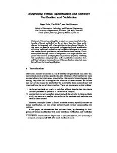
mation manipulated by the application in terms of classes and the relationships among them. An example of an OM for a petrol dispensing system is given in Fig. 1 (taken from [7]). In an OM a class is represented by a box that consists of a partition containing the name of the class, and another containing a list of attributes for the class. Type information for attributes may or may not be shown in an OM. Relationships are depicted as diamond adorned lines between classes. In the diamond the name of the relationship and any attributes associated with it are given. In Fusion, relationships represent optional links between
Terminal
+
enables * Pump pump_id status GunHolsterAssembly
Gun 1
trigger
1
Display
1 kept_in
Holster switch
volume cost grade
status
starts
1 1 controls
Timer standby_period
1 ClutchMotorAssembly
1
1 turns_off
Motor running
Clutch engaged
Fig. 1. Object Model for Pump objects (class instances). Relationships are associated with cardinalities that restrict the number of class instances (objects) that can be linked to each other. A cardinality can be a single number, an integer range, `*' (0 or more), or `+' (1 or more). A black box attached to a relationship indicates that all existing objects of the adjacent class must be linked (i.e., it indicates mandatory links). For example, the relationship enables indicates that every existing Pump object must be linked to 1 or more Terminal objects, and an existing Terminal object may or may not be associated with (0 or more) Pump objects. In Fusion, classes that contain a class structure are called aggregates. The classes in an aggregate are called components. For example, Pump is an aggregate with components GunHolsterAssembly , Display and ClutchMotorAssembly . Fusion also provides constructs for building generalization/specialization structures. Additional constraints on class structures can be expressed as annotations in OMs.
Interface Model. This model de nes the externally observable behavior of the
application. It consists of two models: the Operation Model and the Lifecycle Model. An Operation Model characterizes the observable e�ects of system operations. A system operation is one that can be invoked by users of the system. Each
system operation is described by a Fusion Operation Schema (OS). A Life-Cycle Model characterizes the allowable sequences of system operation invocations for the application.
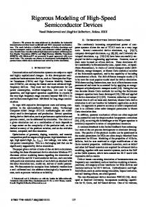
The Data Dictionary. The Data Dictionary provides information about the classes and operations not included in the previous models (e.g., attribute type information). 2.2 Fusion Design Models In the Fusion design phase a system's behavior is modeled in terms of interactions between the objects of the system. The primary model of functional behavior is the Object Interaction Graph (OIG). An OIG is developed for each system operation described in the Operation Model, and it describes the object interactions that accomplish the operation. Graphically, an OIG is a collection of boxes, each representing an object of the system to be implemented, connected by labeled arrows representing message passing between the objects (e.g., see Fig. 2). The order in which interactions can take place is constrained by sequence labels associated with the interactions. Interactions shown in an OIG do not indicate that they must take place; they indicate only the possibility of such an interaction taking place.
(1) enable [pump_id = n] enable_pump(n)
terminal
pumps: Pump
(1.1) reset
display
(1.2) free
(1.3) start motor
clutch
Fig. 2. The enable pump Fusion OIG An individual object is represented as a solid line box, and a collection of objects is represented as a broken line box. One object in an OIG is identi ed as the controller and all other objects are referred to as collaborators. The controller object is distinguished by being the only object with an arrow entering it that
does not originate from another object (or collection of objects) in the OIG. A complete OIG model includes a descriptive text stating the conditions under which interactions take place. An example of an OIG is shown in Fig. 2. The controller in the OIG is the object terminal . The message enable is sent to all objects in the collection pumps with pump id = n . Each selected object in pumps can then send messages reset , free , and start (in that order, as indicated by the interaction sequence labels). The other models of the Fusion design phase are: { a Visibility Graph that models access restrictions and lifetime bindings of objects, { an Inheritance Graph that de nes the inheritance structure of the solution, and { a Class Description (CD) for each class in the system to be implemented. The CDs provide a textual organization of the information found in the other Fusion Design Models.
3 Formalizing Fusion Analysis Models In this section we outline a technique we developed for formalizing the Object and Operation Models of the Fusion Method. The Lifecycle Model is expressed formally in Fusion so there is no need to formalize it. We use models from the petrol system case study given in [7] to illustrate the formalization technique. The OM for the part of the system we will use in our illustration is shown in Fig. 1. In our formalization, an OM is a characterization of the valid states of a system, and the Operation Model speci es operations in terms of their observable e�ects on valid states. Here, a valid state of a system is a linked set of objects that exhibit the properties expressed in the OM (i.e., the structure is consistent with cardinality and other constraints, including those expressed as annotations in the OM). A valid state is called a con guration in this paper.
3.1 Formalizing the Object Model The formalization of an OM results in a Z schema that characterizes the con gurations of the system modeled by the OM. A Z schema consists of two parts: a declaration part in which variables are declared, and a predicate part in which a predicate constraining the declared variables is given. A Z schema characterization of an OM consists of variables representing objects and links among objects in the declaration part, and constraints on the objects and links in the predicate part. The formalization of an OM can be completely automated if the OM annotations are expressed formally in predicate logic. In practice, annotations expressed in predicate logic notation can be signi cantly longer than concise natural language annotations. A related problem is the sometimes lengthy Z speci cations
automatically produced by the OM-to-Z transformation process. We found that properties that are concisely expressed in natural language (e.g., \object identi ers are unique" and \subclasses are disjoint") often required lengthy formal statements. To alleviate this problem we developed a set of high-level Z de nitional constructs, called Z macros, for some commonly occurring properties. Z macros can be automatically translated (`compiled') to Z speci cation elements. Whenever possible, the modeler can use the macros to express annotations. Properties not covered by the macros have to be expressed in predicate logic notation before complete Z speci cations can be produced from OMs. In transforming OMs to Z speci cations, Z macros are used wherever possible in the result output to the modeler. These macros are transformed to `raw' Z notation before they are analyzed by the Z analysis tools. Examples of macros are given throughout this section. Below we outline the steps for formalizing a Fusion OM. Step 1: Formalize Basic Classes. A basic class is a class that is not an aggregate or a subclass in a specialization hierarchy. For each basic class a Z schema called a class schema is produced. A class schema consists of a variable representing the identi er of a class object, and variables representing object attributes. Attribute and object identi er types are speci ed as Z basic types or as pre-de ned Z types (e.g., , the natural number type). In Z a type is a set and a basic type is a set of primitive elements. The basic type declarations and the class schema for a basic class have the following forms: [CLASSNAME ; ATTR1 TYPE ;:::]
ClassName ident : CLASSNAME attr 1 : ATTR1 TYPE ; ::: [Constraints on attribute values ]
In the above CLASSNAME , ATTR1 TYPE ; ::: are Z basic types. CLASSNAME is the set from which identi ers of class objects are drawn and ATTR1 TYPE ; ::: are attribute types. The predicate in the predicate part of the schema constrains attribute values. If the constraints are expressed in natural language in the OM then a human must provide their formal expressions. Note that the formalization forces a type to be associated with each attribute; if one is not given in the OM the FuZE tool uses the capitalized attribute name as the type of the attribute (the type is introduced as a basic type). To illustrate the formalization of basic classes we formalize the Holster , Gun , Clutch , and Motor classes of the petrol system (see Fig. 1). The rst step is to determine the attribute types. Type information not shown in the OM should be in the data dictionary. The data dictionary supporting the petrol system model (not given here for the sake of brevity), indicates that the attribute status of Gun can be one of the following values: Enabled ; Out of Service ; Disabled . It also indicates that the attributes running (in Motor ), engaged (in Clutch ), and switch (in Holster ), can have one of two values: on , o� . The basic types and
class schemata for the classes are given below: Holster [GUNID ; HOLSTERID ] ident : HOLSTERID [MOTORID ; CLUTCHID ] switch : SETTING [TRIGGER] Gun STATUS ::= Enabled j Out of Service ident : GUNID trigger : TRIGGER j Disabled status : STATUS SETTING ::= on j o� Motor ident : MOTORID running : SETTING
Clutch ident : CLUTCHID engaged : SETTING
Step 2: Formalize Aggregate Classes and Subclasses. In this step, aggregates and subclasses are formalized. The class structure in an aggregate must be formalized before the aggregate can be completely formalized. The class structure is essentially an OM, and thus it can be (recursively) formalized using the OM formalization process we are outlining here. The class schema for an aggregate class has the following form: [AGGNAME ;:::]
AggName InternalStruct ident : AGGNAME attr 1 : � ATTR1 TYPE ; ::: [Constraints on attributes ]
InternalStruct de nes the internal structure of the aggregate, that is, it de nes the aggregate's components and relationships between the components. In the predicate part of AggName constraints on the attribute values are given. To illustrate the formalization of aggregates we give the class schemata for GunHolsterAssembly and Pump . The GunHolsterAssembly aggregate is formalized below (the schema characterizing internal structure is on the left): GunHolsterInternal gun : Gun holster : Holster kept in : Gun # Holster kept in 2 1 �
-
[GHAID ] GunHolsterAssembly GunHolsterInternal ident : GHAID
1[fgun g; fholster g]
1 speci es a mandatory 1-to-1 relationship (Fusion reThe macro 1 quires that component instances be linked via enclosed relationships). �
-
The class schema for the Pump aggregate is given below: PumpInternal display : Display gha : GunHolsterAssembly cma : ClutchMotorAssembly controls : GunHolsterAssembly #ClutchMotorAssembly controls 2 1 �
-
[PUMPID ; PUMP ID ] Pump PumpInternal ident : PUMPID pump id : PUMP ID status : STATUS
1[fgha g; fcma g]
Formalization of subclasses is done by including superclass class schemata in subclass class schemata. SubClassName SuperClass attr 1 : ATTR1 TYPE ; ::: [Constraints on attributes ]
3. Specify Constraints on Specialization Hierarchies. In a specialization hierarchy subclasses can be disjoint (i.e., an instance cannot belong to more than one subclass), or not disjoint (i.e., multiple inheritance is possible). Also, the instances of a superclass may all be instances of depicted subclasses (in which case the superclass is said to be abstract), or there may be superclass instances that are not instances of any depicted subclass. Z macros are used to express these properties (not given here for lack of space). Properties of specialization hierarchies are speci ed in a schema, called the con guration schema of the hierarchy. Such a schema has the following form: SpecCon g supers : � SuperClass subs 1 : � SubClass 1; ::: ; subs n : � SubClass n [One or more of the following Z macros included here :] (subs 1;:::; subs n ) partition supers disjoint (subs i ;:::; subs j ) abstract (supers ; subs 1; :::; subs n )
4. Specify relationships and other constraints among classes. This last step results in the OM's con guration schema, that is, a characterization of the OM's con gurations. Con guration schemata have the following form: OMName Spec 1Con g ; ::: [specialization con g schemata ] classobjs 1 : � Class 1; ::: [sets of class objects ] rel ij : Class i # Class j ; ::: [relationships ] [Cardinality and other constraints ]
The con guration schema for an OM expresses constraints on relationships, and restrictions on the sharing of components across aggregates. For example, the presence of a relationship in an aggregate is a reference to a larger relationship, that is, the relationship in the aggregate is a subrelation of a larger relation. This property is stated in the con guration schema for all relationships enclosed in an aggregate. We have de ned the following Z macros for commonly occurring properties: { Relationship cardinalities: We have de ned macros that represent Z formalizations of cardinality constraints. These macros are of the form: q [domain ; range ] p (if the relationship is mandatory black boxes are placed on the appropriate end(s)), where p and q are the cardinalities, domain is the domain of the relationship and range is the range of the relationship. { Object identi er uniqueness: The property that object identi ers in a con guration are unique is captured by the following macro: �
-
b 8 i ; j : s 1 � i :ident = j :ident , i = j unique ids [fs 1; s 2; :::g] = 8 i ; j : s 2 � i :ident = j :ident , i = j ^ :::
^
In the above macro, s 1; s 2;:::; are sets of objects. { Constraints pertaining to sharing of aggregate components: Modelers may
want to restrict the sharing of components across aggregate instances. For example, the following Z macro is used to specify that components cannot be shared across aggregates (in the following, s is the set of instances of the aggregate Agg in a con guration): � physical aggregate (s ): This macro expands to a predicate that prohibits sharing of components of Agg . For example, if aggs is a set of objects of the aggregate Agg that has a single component class comp characterized by the schema COMP (i.e., comp : COMP ), then physical aggregate (aggs ) expands to the following predicate: 8 a 1; a 2 : aggs j a 1:comp = a 2:comp � a 1 = a 2 The restriction as de ned in the above is not recursive, for example, if comp is also an aggregate, then the above macro does not restrict it to be a physical aggregate. For the pump system, the following restrictions are stated as OM annotations (not shown in model given in Fig. 1): { The GunHolsterAssembly aggregate is a physical aggregate, that is, its components are not shared. The ClutchMotorAssembly and the Pump aggregates are also physical aggregates. { All instances of component classes in a con guration must be a component of an aggregate in the con guration. For example, all instances of Gun in a con guration must be a component of one GunHoslterAssembly aggregate instance in the con guration.
The con guration schema for the pump system is given below: PumpSystem terms : � Terminal [terminal instances in con guration ] pumps : � Pump [pump instances in con guration ] timers : � Timer [timer instances in con guration ] enables : Terminal # Pump keptin : Gun # Holster controls : GunHoslterAssembly # ClutchMotorAssembly starts : Timer # Gun turnso� : Timer # Motor enables 2 + � [terms ; pumps ] starts 2 1 1[timers ; fp : pumps � (p :gha ):gun g] turnso� 2S1 1[timers ; fp : pumps � (p :cma ):motor g] keptin = fp : pumps � (p :gha ):kept in g [linked components form a subrelation keptin ] S fp : pumps � p :controls g = controls [linked components form a subrelation controls ] physical aggregate (pumps ) physical aggregate (fp : pumps � p :gha g) physical aggregate (fp : pumps � p :cma g) unique ids (fterms ; timers ; pumps g) ::: [unique ids macros for the components of pumps ] �
�
-
�
-
-
3.2 Formalizing Operation Models In this section we formalize one of the system operations for the petrol system. The formalization of the Fusion Operation Model is only partially mechanizable because the operation descriptions are written mostly in natural language. Currently our tool, given a Fusion operation schema, generates only the declaration part of the corresponding Z operation schema. The formal relationship between the before and after states of the operation must be provided by a human developer. This relationship is stated in the predicate part of the Z operation schema. The Fusion description of the operation enable pump and its corresponding formalization in Z is given below: Operation: enable pump Description: Enables the pump, that is, makes it ready to dispense petrol. Reads: supplied n Changes: p : Pump with p :pump id = n , motor , clutch , display
Sends: Assumes: Result: if p is enabled or out of service then no e�ect otherwise: Status of p is enabled.
Its display has been initialized. its motor is running, and its clutch is not engaged. enable pump �PumpSystem n ? : PUMP ID [input declaration obtained from Reads section ] p ; p : Pump [obtained from Changes section ] p 2 pumps ^ p :pump id = n ? = p :pump id (p :status = Enabled _ p :status = Out of service ) ) pumps = pumps p :status = Disabled ) p :ident = p :ident ^ p :gha = p :gha ^ p :status = Enbaled ^ (p :display ):volume = 0 ^ (p :display ):grade = (p :display ):grade ^ (p :display ):cost = 0 ^ ((p :cma ):motor ):running = on ^ ((p :cma ):clutch ):engaged = o� pumps = (pumps n fp g) [ fp g 0
0
0
0
0
0
0
0
0
0
0
0
0
^
�PumpSystem de nes two pump system con gurations, one representing a con guration before execution of the operation (represented by unprimed variables) and the other representing a con guration after execution (represented by primed variables). In the next section we formalize an OO design for this operation.
4 Formalizing Fusion Design Models In [6] we presented a formalization of OIGs that used the promotion mechanism of Z. We found this particular approach to be cumbersome, and it introduced notation (the � notation) that was not handled well by the static and dynamic analysis tools available in our environment. In this section we present another approach that does not require the use of the � notation.
Design Formalization Example
At the design level, additional classes may be required to implement a solution to the problem, thus there may be some objects in an OIG that are not objects of any class described by the analysis-level Object Model. Though Fusion does not have a Design-level Object Model (DOM), we have found the use of such a model useful in our integrated approach. A DOM can be constructed from information in the Fusion Class Descriptions (CDs). Classes that have objects as attributes in CDs are modeled in a DOM as aggregates in which the components are the object attributes. Object attributes can be bound (i.e., their lifetimes are bound to the lifetime of the aggregate), constant (i.e., they cannot be replaced by another instance), and exclusive (i.e., only the aggregate class can access them). These properties are indicated in the DOM. Part of the DOM for the pump system is given in Fig. 3 (this was obtained from the Class Descriptions given in [7], pages 169-170). A formalized DOM is a characterization of valid design-level states of a system. In our design formalization technique, design models of operations are formalized in terms of relationships between before and after (valid) design states.
Pump pump_id: N status:PumpStatus const.
const.
Terminal
Clutch status:Status
Terminal const., excl., bound
const., excl.,bound
const. *
Display
Pump
const.
Motor
Timer
running:Bool
Fig. 3. Partial Design Object Model for Pump In this section we outline the formalization of the OIG for the enable pump system operation (see Fig. 2). The description associated with the OIG states: The invocation of enable pump triggers the invocation of enable on a pump with identi er n (if there is no such pump then the operation halts, leaving the state unchanged). If the pump is in service and not already enabled then its display is reset, clutch is freed, and its motor is started (else the operation halts). Our formalization of OIGs starts from the leaf objects (e.g., display ), and works its way backward towards the controller object (e.g., terminal ). Information about the e�ects of messages on objects is available from CDs (not given here). Below we give the formalizations of the enable pump leaf messages. reset d ; [before state ] d : Display [after state ] 0
d :ident = d :ident d :grade = d :grade d :volume = 0 d :cost = 0 0 0 0 0
free c ; c : Clutch 0
c :ident = c :ident c :engaged = o� start m ; m : Motor 0 0
0
m :ident = m :ident m :running = on 0 0
In the next step of the formalization, the e�ect of the enable operation is de ned. The description associated with the OIG identi es two execution cases: the case when the pump is disabled and in service, and the other when the pump
is enabled or out of service. The schemata formalizing the two cases are given below: enablesub 1 = b reset ^ free ^ start enable OK enablesub 1 p ; p : Pump n? :
No enable p ; p : Pump n? : 0
0
p :pump id = n ? (p :status = Enabled _ p :status = Out of Service ) p =p
p :ident = p :ident p :pump id = p :pump id = n ? d = p :display ^ d = p :display c = p :clutch ^ c = p :clutch m = p :motor ^ m = p :motor p :status = Disabled ^ p :status = Enabled p :timer = p :timer 0
0
0
0
0
0
0
0
0
0
0
The schema enablesub 1 de nes the combined e�ects of the suboperations. Note that in enable OK no e�ect is de ned for the terminal component of the pump. This is because the terminal component is an object in the OIG whose e�ect is not yet de ned. On the other hand, the timer object does not take part in this operation and so its state is speci ed as unchanged here (p :timer = p :timer ). The enable operation for the pump with identi er n can now be de ned as: enable =b enable OK _ No enable The formalization of the enable pump operation is expressed as follows (there are two cases to consider: the pump is linked to the terminal, and the pump is not linked to the terminal): 0
enable pump OK enable t ; t : Terminal n? :
enable pump notOK t ; t : Terminal n? : 8 p : t :pumps � p :pump id 6= n ? t =t 0
0
p 2 t :pumps t :pumps = (t :pumps n fp g) [ fp g p :terminal = t ^ p :terminal = t 0
0
0
0
enable pump = b enable pump OK
0
_ enable
pump notOK
The next step of the formalization is to promote the enable pump operation to the system level. This is done below: SYSenable pump �DesignPumpSystem 9 en
:::
: enable pump � (en :t 2 terminals ^ terminals = (terminal n fen :t g) [ fen :t g) 0
0
[conjuncts stating that all other con guration elements are unchanged ]
Using the above, and a re nement relationship between DesignPumpSystem (not given here) and PumpSystem (given in previous section), one can establish that the design is consistent with the analysis model of the operation. Veri cation techniques for Z can be used for this purpose. See [16] for more details on design veri cation with Z.
5 Conclusion and future works In this paper we have illustrated the integration of an informal, graphical OOM with a formal speci cation technique. We used the formal models to tie together models produced in a particular phase of development, and across development phases. At the analysis level, the formalized Object Model characterizes the state a�ected by the operations speci ed in the formalized Operation Model. The formalized Object Model provides terms that can be used to express the e�ect of system operations precisely. Using the formalized models one can rigorously do internal consistency checks of models, as well as consistency checks across the models. At the design level, the formalization of an OIG produces a model that can be formally veri ed against the formalized Operation Model. We are currently developing rigorous re nement techniques for Fusion design. The intent is to develop an analysis and design development environment in which the complementary nature of formal and informal OO methods is exploited. We are also extending the prototype tool FuZE to support the techniques outlined in this paper.
References 1. Brian W. Bates, Jean-Michel Bruel, Robert B. France, and Maria M. LarrondoPetrie. Formalizing Fusion Object-Oriented Analysis Models. In Elie Najm and Jean-Bernard Stephani, editors, Proceedings of the First IFIP International Workshop on Formal Methods for Open Object-based Distributed Systems, Paris, France. Chapman & Hall, London, UK, 4{6 March 1996. 2. Grady Booch. Object-Oriented Analysis and Design with Applications. Benjamin/Cummings, Menlo Park, CA, Second edition, 1994. 3. Jonathan P. Bowen and J. Anthony Hall, editors. Z User Workshop, Cambridge 1994, Workshops in Computing. Springer-Verlag, New York, 1994. 4. Stephen M. Brien and John E. Nicholls. Z base standard. Technical Monograph PRG-107, Oxford University Computing Laboratory, Wolfson Building, Parks Road, Oxford, UK, November 1992. Accepted for standardization under ISO/IEC JTC1/SC22. 5. Jean-Michel Bruel, Robert B. France, Bharat Chintapally, and Gopal K. Raghavan. A Tool for Rigorous Analysis of Object Models. In Proceedings of the 20th International Conference on Technology of Object-Oriented Languages and Systems (TOOLS'96), Santa Barbara, California, July 29{August 2 1996. 6. Jean-Michel Bruel, Robert B. France, Maria M. Larrondo-Petrie, Bharat Chintapally, and Gopal K. Raghavan. CASE-based Rigorous Object-Oriented Modeling.
7. 8. 9. 10. 11. 12. 13. 14. 15. 16. 17.
In Proceedings of the Northern Formal Methods Workshop, Bradford, UK, 23{ 24 September 1996. Derek Coleman, Patrick Arnold, Stephanie Bodo�, Chris Dollin, Helena Gilchrist, Fiona Hayes, and Paul Jeremaes. Object-Oriented Development: The Fusion Method. Prentice Hall, Englewood Cli�s, NJ, Object-Oriented Series edition, 1994. Dan Craigen, Sentot Kromodimoeljo, Irwin Meisels, Bill Pase, and Mark Saaltink. EVES: An Overview. In S. Prehn and W. J. Toetenel, editors, VDM'91: Formal Software Development Methods, volume 551 of Lecture Notes in Computer Science, pages 389{405. Springer-Verlag, 1991. Volume 1: Conference Contributions. Robert B. France and Jean-Michel Bruel. The Role of Integrated Speci cation Techniques in Complex System Modeling and Analysis. In Proceedings of the Workshop on Real-Time Systems Education (RTSE'96), Daytona Beach, Florida, 20 April 1996. J. Anthony Hall. Specifying and Interpreting Class Hierarchies in Z. In Bowen and Hall [3], pages 120{138. Jonathan A. R. Hammond. Producing Z Speci cations from Object-Oriented Analysis. In Bowen and Hall [3], pages 316{336. I. Jacobson. Object oriented software engineering. Addison-Wesley, 1992. Xiaoping Jia. An Approach to Animating Z Speci cations. Division of Software Engineering, School of Computer Science, Telecommunication, and Information Systems, DePaul University, Chicago, IL, USA, 1995. Xiaoping Jia. ZTC: A Z Type Checker, User's Guide, version 2.01. Division of Software Engineering, School of Computer Science, Telecommunication, and Information Systems, DePaul University, Chicago, IL, USA, May 1995. Available via anonymous ftp at ise.cs.depaul.edu. J. Rumbaugh, M. Blaha, W. Premerlani, F. Eddy, and W. Lorensen. ObjectOriented Modeling and Design. Prentice Hall, 1991. J. Michael Spivey. The Z Notation: A Reference Manual. Prentice Hall, Englewood Cli�s, NJ, Second edition, 1992. R. Wirfs-Brock and B. Wilkerson. Designing object oriented software. PrenticeHall, 1990.
This article was processed using the LaTEX macro package with LLNCS style