Mathematical and Computer Modelling of Dynamical Systems, 2003, vol. ... The
paper presents a methodology to model the collision between soccer robots.
Mathematical and Computer Modelling of Dynamical Systems, 2003, vol. 9, no. 2, pp. 137-150. ∗
Robot Soccer Collision Modelling and Validation in Multi-Agent Simulator ∗ ˇ ˇ Cˇ ∗ G. KLANCAR , M. LEPETICˇ ∗ , R. KARBA∗ AND B. ZUPANCI
SUMMARY The paper deals with mathematical modelling and simulation of collisions in robot soccer representing ideal playground for studying multi-agent mobile systems. It involves robot and ball dynamic behaviour and focuses mainly on their collisions study and their realization. Some vital parts of the simulator are explained and modelled in more detail, beginning with the simple model of ball and robot motion and continuing with more complex collision models. Special consideration is given to collision between robots. The design of such model takes two steps. In the first, information about possible collision is obtained. The second step realizes collision by determining appropriate force impulse. The results from model verification are presented. It is shown that the developed model represents a good basis for realistic, yet simple enough, collision simulation. The paper concludes with some remarks and ideas for future work.
Keywords: simulator, multi-agent system, collision detection, modelling, discontinuous simulation.
1. INTRODUCTION In the last two decades the concept of multi-agent mobile systems has been observed in many computer simulations, laboratory examples and in some practical applications. Inspiration for the design of such systems could be found in nature, as for example: incredible group organization of ants, bees, group of hunting predators etc. Here the importance of organization, work and information sharing as well as communication can easily be identified. Researchers try to realize at least piece of this idea by multi-agent robot systems applications [12]. Among them robot soccer is very popular and serves as a perfect example of multi-agent systems in the last few years [4] [11]. It gives the possibility to study multi-agent related topics [12] such as: robot soccer, group formations, robots pushing objects, study of social science aspects, study of cooperation paradigm, learning methods and algorithms as well as mechanisms for adaptations and behaviour ∗ Address
correspondance to: G. Klanˇcar, Faculty of Electrical Engineering, University of Ljubljana, Trˇzaˇska 25, 1000 Ljubljana, Slovenia.
ˇ G . KLAN CAR ET AL .
2
assignment in multi-agent systems, opponent plan or strategy identification, reactive and cognitive capabilities of agents behaviour. However, also the possibility to study the capabilities of a single agent is enabled: optimal path planning and following algorithms, static and dynamic obstacle avoidance methods and prediction algorithm study (to predict proper position of other agents and the ball taking into account capabilities of the agent and to predict plans of the opponents). The reason for robot soccer popularity originates in the fact that it efficiently combines many research interests [14] besides the already mentioned it also involves multi-agent cooperation, game strategy, real-time data and image processing, robotic vision, artificial intelligence and control. The area has also proven to be very usable in engineering education not only because of the reasons stated above but also because of its attractiveness [10]. The paper presents a methodology to model the collision between soccer robots which is an important part of a multi-agent simulator for robot soccer game. It is implemented in Matlab Simulink and C++ environment. Both implementations are used for design and verification of control algorithms as well as for appropriate robot soccer competitions if they are organized in the simulation environment. Important feature, provided collisions are solved realistically, is that control algorithms designed on simulator can later be used in real game situation without major changes. The reprogramming of algorithms when testing them on real playground is thus not needed. Main motivation for the development of such a simulator is to design and study multi-agent control and strategy algorithms in FIRA Small League MiroSot category (3 against 3 robots). However on FIRA (Fedration of International Robot soccer Association) official site (www.fira.net) there exists a simulator for SimuroSot league, which could only be used in Middle League MiroSot (5 against 5 robots). Similar simulator was build in Taiwan [8] where robot motion is simulated by dynamical model while the collisions are oversimplified. A number of different collisions can appear in robot soccer game. Their realization is undoubtedly essential for realistic simulator. However, the most challenging and problematic from the modelling point of view is collision between robots which is presented in more detail. Good mathematical background in rigid body collisions modelling and simulation can be found in [1]. Another useful contribution in the field of robotic simulators is [7] where collisions are treated by spring-dumper approach rather than by impulse force only. The use of spring-dumper linkage in the collision makes change of velocities continuous, which is less problematic for simulation than discontinuous change of velocities [5] obtained by impulse usage. However, spring dumper coefficients are not easy to identified and also collisions when observed from macroscopic time scale (as it is simulation) are indeed discontinuous events. In the paper some novel ideas of collision formulation and realization are used. The presented simulator is developed mainly as a tool in control and strategy design of multi-agent system in real world and therefore needs to be realistic. Strategy design could be performed also on real plant but there are some important reasons which
3
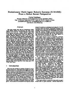
ROBOT S OCCER C OLLISION M ODELLING . . . Frame-Grabber Computer Vision Application Shared Memory Objects Positions
Control Application
PC Transmitter
Fig. 1. Robot soccer setup.
benefit the usage of realistic simulator. They are stated in the paper. Collisions are simply solved by mathematically correct discontinuous change of velocities (states of the velocity integrators), which is more convenient for realization than simulating collisions by applying impulse force [1] [7]. The problem of collision detection and the method of finding exact time of the collision are exposed too. The paper is organized as follows. First a brief system overview is revealed, followed by the mathematical model derivation of basic agents (robots and ball) and short description of different collisions in the game. Then the proposed model of robots collision, namely collision detection and its realization, is explained in more detail. Validation results of the developed mathematical model describing collisions between robots is depicted in section 5. The paper ends with conclusions and some ideas for future work.
2. SYSTEM OVERVIEW The robot soccer set-up (see Figure 1) consists of six MiroSot category robots (for two teams) of size 7.5cm cubed, orange golf ball, rectangular playground of size 1.5×1.3m, JAI MCL-1500 camera, frame-grabber Matrox Meteor II, and personal computer. The vision part of the program processes the incoming images to identify the positions and orientations of the robots and the position of the ball. Finally, the control part of the program calculates the linear and angular speeds, v and ω that robots should have in the next sample time according to current situation on the playground. Calculated speeds are sent to the robots by radio connection. As seen from Figure 1 there are two applications running on personal computer. Namely computer vision and control application. The communication among them is realized through shared memory. Figure 2 depicts the situation where real system (playground with robots and ball) is replaced by simulator. Robots and ball movements are simulated in Matlab Simulink
ˇ G . KLAN CAR ET AL .
4
Shared Memory Objects Positions
Simulator Control Application
PC
Shared Memory Robot Commands
Fig. 2. Simulator setup.
environment or in C++ language while control algorithm and shared memory for object positions remain unchanged. Communication between control and simulator is again realized through another shared memory for calculated robot speeds (commands). Which are the important advantages of the simulation environment? In real game robot positions and orientations of the object from the playground are obtained by camera and computer vision program. The role of simulator is therefore to avoid the usage of hardware (except PC), which is expensive and needs a large place to be set up. In addition such system is in general not mobile and it is time consuming to manipulate with. Finally the organization of mass competitions is expensive and problematic. Simulator runs in real time so that data coming from simulator appear in the same time intervals as in real set-up. However, it is possible for simulator to run faster in order to speed up experiments or slower than real time to enable easy visualization of the scene. Another advantage of the structure presented in Figure 2 is that all modules for both competitors (simulator, two control applications) can run on one computer. As already mentioned the same control program can without any change be applied to real or simulated game.
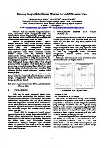
3. MATHEMATICAL MODELLING To simulate robot soccer game first mathematic motion equations should be derived. The playground activities consist of two kinds of moving objects: robot and ball. Therefore their motion modelling [9] is presented in the sequel. 3.1. Robot Model The robot has a two-wheel differential drive located at the geometric centre, which allows zero turn radius and omni-directional steering because of nonholonomic constraint [6]. Inputs to the model are angular velocities of right and left wheel (ωR , ωL )
5
ROBOT S OCCER C OLLISION M ODELLING . . .
y
wL v
r j
w (x,y) L wR
x
Fig. 3. Symbol description.
while the outputs are position data (x,y,ϕ). Robots angular (ω) and linear (v) velocities are obtained from the following set of equations v = (ωR + ωL ) 2r ω = (ωR − ωL ) L1
(1)
where L is the robot size (see Figure 3) and r is wheel radius. Dynamics of both motors can be modelled by first order systems ω˙ L = ω˙ R =
1 T (uL − ωL ) 1 T (uR − ωR )
(2)
where T is time constant and uL and uR stand for voltage values (reference angular velocities of wheels) applied to motors. The robot kinematics is finally defined as x˙ cos(ϕ) y˙ = sin(ϕ) ϕ˙ 0
· ¸ 0 v 0 · ω 1
(3)
3.2. Ball Model Model of the ball rolling across the playground can be treated as independent of both directions. Mathematical modelling of ball motion can be efficiently derived using Lagrangian equations [15]
ˇ G . KLAN CAR ET AL .
6
· ¸ d ∂L ∂L ∂P − + = F (t) dt ∂ q˙s ∂qs ∂ q˙s
(4)
where Lagrangian L represents difference between kinetic and potential energy, P is power function (dissipation function), qs stands for generalized coordinate and F (t) is external force respectively. For dimension x the following equation is obtained 1 1 1 L = WK − WP = mx˙ 2 + J ϕ˙ 2 = 2 2 2
µ
J m+ 2 R
x˙ 2
(5)
where m stands for ball mass, J for its moment of inertia, ϕ for angle of ball rotation and R for ball radius. The power function is 1 fv x˙ 2 + Kc mg x˙ (6) 2 wherefv is viscos friction coefficient, Kc is Coulomb coefficient of rolling friction and g gravitation acceleration. Moment of inertia of the ball is defined as P =
2 mR2 (7) 5 After inserting Equations (5) and (6) in Equation (4) for qs = x the following relation is obtained J=
x ¨=
F (t) − x˙ · fv − Kc mg F (t) − x˙ · fv − Ff = ± ± J m + R2 m + J R2
(8)
In the simulation the Coulomb friction force (Fc = Kc mg) has to be used only when the ball is moving otherwise this force will start to push the ball in opposite direction. Because external force F (t) takes nonzero impulse values only when collisions appear and its values are nearly always larger than Fc , the Karnopp’s model of Coulomb friction [2] [3] is not required. Friction force (Ff ) is thus determined by x˙ = 0 0, ˙ 0 < |x| ˙