Robots Controlled by Neural Networks Trained based on Brain Signals Genci Capi, Toshihide Takahashi, Kazunori Urushiyama and Shigenori Kawahara, Member, IEEE
Abstract— Recent works on Brain Machine Interface (BMI) has given promising results for developing prosthetic devices aimed at restoring motor functions in paralyzed patients. The goal of this work is to create a part mechanical, part biological robot that operates on the basis of the neural activity of rat brain cells. In our method, first the rat learns to move the robot by pressing the right and left lever in order to get food. Then, we utilize the data of multi-electrode recordings to train artificial neural controllers, which are later employed to control the robot motion based on the brain activity of rats. The results show a good performance of artificial neural network controlling the real robot.
C
I. INTRODUCTION
ONTROLLING the robot with the brain signals is a very challenging research work ([1]~[5]). This approach has proved useful for helping paralyzed or ‘locked in’ patients develop ways of communication with the external world [6–11]. In addition, these experiments have demonstrated that animals can learn to utilize their brain activity to control the displacements of computer cursors ([4], [5]) or one-dimensional to three-dimensional movements of simple and elaborate robot arms ([1], [3]). Many electro-biological signals can be used in connection with BMIs. Some of the more commonly adopted signals are the Electro-Myographic (EMG), the Electro-Oculographic (EOG) and the Electro-Encephalographic! (EEG) signal. Many research groups have shown impressive results with a microelectrode arrays in motor control areas of the cortex and adaptive algorithms to reconstruct a desired signal using both linear and non-linear algorithms. The EEG signal corresponds to the electrical potential due to brain (neuron) activity, and can be acquired on the scalp (signal amplitude usually under 100 μV) or directly on the cortex (called Electrocorticography – ECoG), the surface of the brain (signal having about 1 - 2 mV of amplitude). Despite these initial results, there are several issues that need to be considered. For example, although most agree that a BMI designed to reproduce arm/hand movements will require long-term and stable recordings from cortical neurons through chronically implanted electrode arrays ([12], [13], G. Capi and T. Takahashi are with the Department of Electrical and Electronic Systems Eng., Faculty of Engineering, University of Toyama, Gofuku Campus, 3190 Gofuku, Toyama, 930-8555, Japan. (e-mail:
[email protected]). K. Urushiyama and S. Kawahara are with the Department of Life Sciences and Bioengineering., Faculty of Engineering, University of Toyama, Gofuku Campus, 3190 Gofuku, Toyama, 930-8555, Japan.
[14]), there is considerable disagreement on what type of brain signal (single unit, multiunit, or field potentials [15]) would be the optimal input for a such a device. At the cortical level, a number of different areas are connected in planning and execution of voluntary natural movements, such as grasp or reach. The goals of this research work are (1) to apply knowledge rat’s neuro-musculo-skeletal motion control to a neural controlled robotic system, and (2) to demonstrate that such a system is able to obtain responses in a similar way to the voluntary rats movements in comparable experiments. The final goal of this work is to understand the working and possibly, the capabilities of the neural circuits in controlling robotic systems. In order to achieve these goals, we have developed a system where the rat control the robot motion by pressing the right and left button in order to get food in scenarios that change from simple to more complicated ones. In an early work, Skinner ([16]) set up a pigeon training area which consisted of a pigeon in a man's sock looking at a picture of a 'target'. The pigeon could then peck on one of four levers that moved the 'target' up, down, left and right. This prototype seemed to work with the pigeons keeping the target in the centre. In our work, we utilized the 8 neurons recordings of the rat frontal cortex and the right and left lever signals to train artificial neural network, which is later used to control the robot. The results indicate that the robot motions generated by the artificial neural controller and real data collected during the experiments were very similar. This paper is organized as follows. Firstly, the developed system for rat training is described in Section II. The structure of neural network is presented in Section III. Experimental results with the neural network controlling the real robot are addressed in Section IV. Finally, a discussion on experimental results and future works are given in Section V. II. DEVELOPED SYSTEM Conceptually, a BMI maps some level of neural signal into commands to control an external device e.g. robotic arm, cursor. In order to train the rat to control the robot by pressing the right or left lever, we developed a system, which recognize the lever signals and convert them into the robot motion (Fig. 1). This system is composed by an electronic circuit (Fig. 2) using PIC18F452 and ADM3202. The circuit is connected with the PC, which runs Matlab, through RS232 serial cable. Based on the input data, the
e-puck robot motion is determined and sent by a Bluetooth connection. The rat’s food is placed in the upper part of the e-Puck robot, as shown in Fig. 3. The rat controls the e-puck robot motion in the environment and brings it close to his mouth in order to get food. The robot utilizes the data of proximity sensors to stop moving when it reaches the rats place. A. E-puck robot In the experiments presented here, we utilize the e-Puck robot to carry the rat’s food. We selected this robot because it is small; it has a good structure, is flexible, user friendly, and has good robustness and simple maintenance. An e-Puck robot consists of a cylindrical body of 75 mm in diameter (Fig. 4). It has several outputs which can execute behavior or ‘broadcast’ information into the environment. The e-puck robot is equipped with two wheel motors, which can rotate independently; Eight LEDs placed around the body, which can be turned on and off independently; Two body LEDs, red and green; A speaker, which can play sound files; A Bluetooth module to communicate with a PC or other e-Pucks using designated Bluetooth protocols; A RS-232 connection for serial communication with a PC or debugger; To perceive its environment the e-Puck is equipped with the following sensors: Eight infrared sensors, which have dual purpose, they can be used as proximity sensors to perceive obstacles or as light sensors to perceive luminosity; Three microphones, which can detect sound; An accelerometer, which measures relative movement in three dimensions; A camera, which typically captures a subsample 40x40 pixel image at 4 fps in color or 8 fps in grayscale mode.
Later, the food is placed on e-puck robot and the rat learns to direct the robot by pressing the right and left levers in scenarios that change from simple to more complicated ones, as follows: z The robot is placed in front of the rat and it moves straight forward when the right or left lever is pressed (Fig. 6a); z The robot is placed in the right (left) side of the rat and it follows half of a U-shape trajectory when only the right (left) lever is pressed (Fig. 6b); z The robot is placed initially on the right or left side of the rat and it moves to the right or left of a U-shape when the respective lever is pressed (Fig. 6c).
Fig. 2. PIC circuit.
B. Rat training In a typical experiment, food-deprived rats are trained to perform an instrumental action (such as lever pressing) to obtain a rewarding outcome (food). At the beginning, three rats (Wistar/ST, male, 10 weeks old) were being trained to learn to press the right or left lever as follows: z press the right or left button to get food supplied manually (Fig. 5a). z press levers as above, except with their head restricted (Fig. 5b).
Fig. 1. Developed system.
Fig. 3. Rat directing the robot by pressing the right and left lever.
Fig. 4. e-Puck robot.
III. ARTIFICIAL NEURAL NETWORK
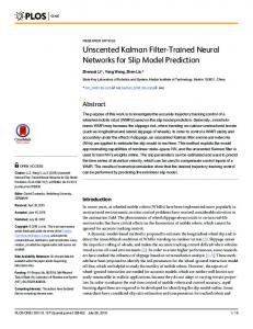
A. Training The response rates during training to press the right and left lever are shown in Fig. 7. Fig. 7(a) and Fig. 7(b) show the frequency and time that the lever was kept pressed for the right and left lever, respectively. The rats successfully learned to press the lever with their head restricted. The rat first learned to press the right (Fig. 7(a)) and then the left lever (Fig. 7(b)). Fig. 7(c) shows the left lever response rates results of the rat, which had already received training with its head restricted. The rat controlled the e-puck robot positioned in its left side in order to get food. Compared to the previous scenario, the rat learned to press the lever after three days of training. The rat first learned to press the right lever (the robot was placed initially in the right side) and then to press the left lever (the robot was placed initially in the left side). Finally, the rat was trained with the U-shape trajectory.
100
proportion(%)
Predictions of lever position based on recordings of cortical neurons were obtained by applying an artificial neural network. We employ a Multilayer Perceptron Neural Networks (MPLNN), which is a good tool for classification purposes. It can approximate almost any regulatory between its input and output. In our model, P(t) is a matrix of the input patterns with each column corresponding to the brain recorded data. The T(t) is a matrix of the target outputs, with samples of the lever position. The MPLNN weights are adjusted offline by supervised training procedure. After training the MLPNN, it can successfully apply the acquired skills to the previously unseen samples. It has good extrapolative and interpolative abilities. We have used hyperbolic tangent as an activation function of hidden neurons and sigmoid function for output neurons. In practice, the value of the output neurons is not exactly ”0” or ”1”. They vary in the range [0; 1] and the vicinity to the ideal values depends on the MPLNN confidence. The closer output values to ideal, the more confidence to the NN decision. In our implementation, the output is 1 if the value is above the threshold (0.9) or 0 otherwise.
IV. RESULTS
80 60 40
frequency time
20 0 1
(a)
2
(b)
3 Training day
4
5
(a)
Fig. 5. Rat during training. (a) Head free; (b) Head restricted.
proportion(%)
100 80 60 40
frequency time
20 0 1
(a)
2
3
Training day
4
5
(b)
(b)
proportion(%)
100 50
frequency time
0 1
2
3
Training day
4
5
(c) (c) Fig. 6. Rat during training to control the e-Puck robot. (a) Straight motion; (b) Half right and half left of a U-shape; (c) U shape.
Fig. 7. Training results. (a) Pressing the right lever with the head restricted; (b) Pressing the left lever with the head restricted; (c) Pressing the left lever to control the e-pack robot placed in the left side.
200 0 -200
100 90
200 0 -200
70 60
200 0 -200
Righ Left
50 40 30 20
μV
Percent correct(%)
80
10 0 1
2
3
4
200 0 -200
Fig. 8. Overall percentage of correct responses for each day of training when the e-puck robot was placed initially in the left side.
200 0 -200
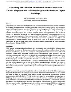
Fig. 9. Recorded data. 2500 2000 1500 1000 500
μV
B. Neural Network After the surgery the animals were placed for daily recording sessions. All the data (neural signal, reward times, and lever position) are time synchronized. The right and left lever position was recorded continuously throughout the session. In order to minimize the number of animals used, it is necessary to maximize time for BMI experiments after surgery. In our experiments, there are 8 electrodes implanted in the rat frontal cortex. Fig. 9 shows all the recorded data in an interval of 30 min, while the rat pressed the left and right lever to control the robot motion in a U-shape trajectory. As the figure shows, some parts of the recorded brain signals are affected by noise. In order to select the best data to train the artificial neural controller, all 8 neural recordings are weighted by the same coefficient and placed together, as shown in Fig. 10. In our model, we selected 320 data to train the artificial neural controller. The number of training data for each of four levers position is nearly the same. The neural network has 8, 40, and 2 units in input, hidden and output layer, respectively. The learning continued for 10000 epochs, as shown in Fig. 11. The performance of trained neural network was evaluated using brain recordings data, which were not used during training. The results show that the neural network model achieved an 80 % prediction accuracy rate, for the input brain signals not used during training. It must be noted that the output of neural network was exactly the same with the recorded lever positions for the input signals used during training. The output of artificial neural controller, which correspond to the right and left lever, directly control the e-Puck robot motion, as follows:
200 0 -200 200 0 -200
Training day
Fig. 8 shows the overall percentage of left and right lever pressing for each day of training session when the e-puck robot was placed initially in left side. This training session started after the rat learned to control the e-puck robot placed initially in the right side. Therefore, in the first day of training the rat pressed primarily the right lever. The rat almost exclusively pressed the left lever from the second day on.
200 0 -200
0 -500 -1000 -1500 -2000
0
0.5
1
1.5
2
2.5
3 x 10
6
Fig. 10. Weighted data.
z No lever pressed [0 0] – right back motion; z Pressing the left lever [1 0] – right forward motion; z Pressing the right lever [0 1] – left forward motion; z Both levers pressed [1 1] – straight forward motion. Ten different sets of brain activity data for each of lever positions were used to evaluate the performance of trained neural network. The video capture of robot motion generated using the rat collected data and artificial neural network are shown in Fig. 12. This figure indicates that the robot motions generated by the artificial neural controller and real data collected during the experiments were very similar. The robot motions generated by the NN using as input the brain signals when no lever was pressed ([0, 0]) are shown in Fig. 12(a). Two out of ten robot motions were not correct. The neural network output was [0, 1] and the robot motion was left forward instead of right back. The NN result using the neuron signals when the rat pressed the left lever ([1, 0]) is shown in Fig. 12(b). The first and last robot motions are different. First
the robot moves right back ([0, 0]) and the last motion is straight forward, which correspondent to both levers pressed situation ([1, 1]). The largest number of not correct answers of NN was generated by the neuron signals when the rat pressed the right lever. Fig. 12(c) shows that six times the output of the neural controller was correct [0, 1] (left forward motion), and four times the output was not correct [0, 0] (right back motion).
The reason is that from 8 electrodes used to record the brain activity, 6 of them were in the right half and two in the left half of the cortex. With only two data the neural network was unable to learn the mapping of input signals to the lever position. The robot motion generated by the brain signals when the rat pressed both levers was 100% correct (Fig. 12(d)). V. CONCLUSION
Fig. 11. MSE of neural network during training.
In this paper, we presented some preliminary results on training the rats to get food by controlling a mobile robot. The results showed that the rat learned to control the robot by pressing the right and left buttons in simple and complex environment settings. We utilized the brain recorded data to train artificial neural network and evaluated their performance in controlling the mobile robot motions. There were three main components to the system: neural signal processing, control algorithm, and learning algorithm. The input to the system was the neural signal of the rats and the output of the system was the lever positions. The results showed a good performance of artificial neural networks. ACKNOWLEDGMENT This work is supported by a Grant-in Aid for Young Scientists (B) Research of the Ministry of Education, Science, Sport and Culture, Japan. Grant number 21700220. REFERENCES [1]
[2] [3] [4] [5] [6] [7] [8] [9] [10] [11] [12] [13] [14] Fig. 12. Robot motion controlled by rats collected data and neural network.
Chapin, J. K., Markowitz, R. A., Moxon, K. A., and Nicolelis, M. A. L. (1999). Direct real-time control of a robot arm using signals derived from neuronal population recordings in motor cortex. Nature Neuroscience 2, 664-670. Talwar SK, Xu S, Hawley ES, Weiss SA, Moxon KA, et al. (2002) Rat navigation guided by remote control. Nature 417:37–38 Wessberg J, Stambaugh CR, Kralik JD, Beck PD, Laubach M, et al. (2000) Real-time prediction of hand trajectory by ensembles of cortical neurons in primates. Nature 408:361–365. Serruya MD, Hatsopoulos NG, Paninski L, Fellows MR, Donoghue JP (2002) Instant neural control of a movement signal. Nature 416:141–142. Taylor DM, Tillery SI, Schwartz AB (2002) Direct cortical control of 3D neuroprosthetic devices. Science 296:1829–1832. Hinterberger, T. et al. (2005) Neuronal mechanisms underlying control of a brain–computer interface. Eur. J.Neurosci. 21, 3169–3181. Kubler, A. et al. (2001) Brain–computer communication: unlocking the locked in. Psychol. Bull. 127, 358–375. Kubler, A. et al. (2001) Brain–computer communication: selfregulation of slow cortical potentials for verbal communication. Arch. Phys. Med. Rehabil. 82, 1533–1539. Obermaier, B. et al. (2003) Virtual keyboard controlled by spontaneous EEG activity. IEEE Trans. Neural Syst. Rehabil. Eng. 11, 422–426. Obermaier, B. et al. (2001) Information transfer rate in a five-classes brain–computer interface. IEEE Trans. Neural Syst. Rehabil. Eng. 9, 283–288. Sheikh, H. et al. (2003) Electroencephalographic (EEG)-based communication: EEG control versus system performance in humans. Neurosci. Lett. 345, 89–92. Nicolelis MAL (2001) Actions from thoughts. Nature 409:403–407. Nicolelis MAL (2003) Brain–machine interfaces to restore motor function and probe neural circuits. Nat Rev Neurosci 4:417–422. Donoghue JP (2002) Connecting cortex to machines: Recent advances in brain interfaces. Nat Neurosci Supp 5:1085–1088.
[15] Pesaran B, Pezaris JS, Sahani M, Mitra PP, Andersen RA (2002) Temporal structure in neuronal activity during working memory in macaque parietal cortex. Nat Neurosci 5:805–811. [16] Skinner, B.F. (1948). 'Superstition'in the Pigeon. Journal of Experimental Psychology, 38, 168-172.