Apr 4, 2014 - j=1 uj Ïj eâi âj n=1 vnÏ also satisfies the relation. (26). xJ = fdJ ⦠fdJâ1 â¦Â·Â·Â·â¦ fd1 (0). Since f1,...,f4 are invertible maps, we also have. (27). 0 = fâ1.
ROBOT’S HAND AND EXPANSIONS IN NON-INTEGER BASES
arXiv:1111.1991v2 [math.OC] 4 Apr 2014
ANNA CHIARA LAI AND PAOLA LORETI
Abstract. We study a robot hand model in the framework of the theory of expansions in non-integer bases. We investigate the reachable workspace and we study some configurations enjoying form closure properties.
1. Introduction Aim of this paper is to give a model of a robot’s hand based on the theory of expansions in non-integer bases. Self-similarity of configurations and an arbitrarily large number of fingers (including the opposable thumb) and phalanxes are the main features. Binary controls rule the dynamics of the hand, in particular the extension and the rotation of each phalanx. Our robot hand is composed by an arbitrary number of fingers, including the opposable thumb. Each finger moves on a plane. Every plane is assumed to be parallel to the others, excepting the thumb and the index finger, that belong to the same plane. A discrete dynamical system models the position of the extremal junction of every finger. A configuration is a sequence of states of the system corresponding to a particular choice for the controls, while the union of all the possible states of the system is named reachable workspace for the finger. The closure of the reachable workspace is named asymptotic reachable workspace. Our model includes two binary control parameters on every phalanx of every finger of the robot hand. The first control parameter rules the length of the phalanx, that can be either 0 or a fixed value, while the other control rules the angle between the current phalanx and the previous one. Such an angle can be either π, namely the phalanx is consecutive to the previous, or a fixed angle π − ω ∈ (0, π). The structure of the finger ensures the set of possible configurations to be selfsimilar. In particular the sub-configurations can be looked at as scaled miniatures with constant ratio ρ, named scaling factor, of the whole structure. This is the key idea underlying our model and our main tool of investigation. We establish a connection between our model and the theory of iterated function systems and the theory of expansions in non-integer bases. This yields several results describing the reachable workspace, some conditions on the parameters in order to avoid self-intersecting configurations and a description of a class of configurations satisfying a form closure condition. 1.1. Previous work and motivations. The fingers of our robot hand are planar manipulators with rigid links and with a (arbitrarily) large number of degrees of Key words and phrases. Robot hand, discrete control, expansions in non-integer bases, expansions in complex bases. 1
2
ANNA CHIARA LAI AND PAOLA LORETI
freedom, that is they belong to the class of so-called macroscopically-serial hyperredundant manipulators (the term was first introduced in [CB90]). Hyper-redundant architecture was intensively studied back to the late 60’s, when the first prototype of hyper-redundant robot arm was built [AH67]. The interest of researchers in devices with redundant controls was motivated, among others, by the ability to avoid obstacles and the ability to perform new forms of robot locomotion and grasping (see for instance [Bai86], [Bur88] and [CB95]). A large number of papers were devoted in the literature to both continuously and discretely controlled hyper-redundant manipulators. Our approach, based on discrete actuators, is motivated by their precision with low cost compared to actuators with continuous range-of-motion. Moreover the resulting discrete space of configurations reduces the cost of position sensors and feedbacks. In [IC96] the inverse kinematics of discrete hyper-redundant manipulators is investigated. Throughout the analysis of the reachable workspace (and in particular of the density of its points) an algorithm solving the inverse kinematics problem in linear time with respect the number of actuators is introduced. In general the number of points of the reachable workspace increases exponentially, the computational cost on the optimization of the density distribution of the workspace is investigated in [LSD02] Note that the concept of a binary tree describing all the possible configurations underlies above mentioned approaches, in our method the self-similar structure of such a tree gives access to well-established results on fractal geometry and iterated function systems theory. Robotic devices with a similar fractal structure are described in [MED96]. Other approaches to the investigation of the reachable workspace include those based on harmonic analysis [Chr96], and Fast Fourier Transform [WC04]. Finally we refer to [Chr00] for a description of the geometry of the reachable workspace. In our model every link (phalanx) is controlled by a couple of binary controls. The control of the rotation at every joint is a common feature of all above mentioned manipulators. The study of a control ruling the extension of every link has twofold applications. In one hand it can be physically implemented by means of telescopic links, that are particularly efficient in constrained workspaces (see [AP06]). On the other hand, our model can be considered a discrete approximation of continuous snake-like manipulators - see for instance the approach in [And08] to the discretization of a continuous curve and its applications to snake-like robots. Form closure is a property of grasping mechanisms originally investigated in [Reu75] and it concerns the ability of the manipulator of totally or partially constrain the motion of a manipulated object. We refer to [Bic95] for an overview on the closure properties of manipulators and their applications. In our analysis we shall focus on the case of planar manipulators constraining a circle without considering external forces. Some numerical examples are given for three-dimensional manipulators constraining a cylinder. This investigation has twofold motivations: in one hand, in our model the length of links decreases exponentially and we want to understand by an explicit geometric argument how much this assumption affects the capability of the manipulator of interacting with other objects. On the other hand this simplified setting enlightens how self-similarity can be used in order to extend local geometric properties to a wider class of configurations. We remark that a more complete analysis would involve the investigation of the stronger condition
ROBOT’S HAND AND EXPANSIONS IN NON-INTEGER BASES
xk−1
xk
xk−1
xk
3
xk+1
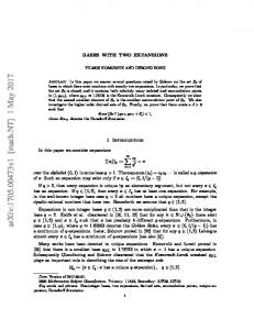
π − ω1 π − ω1 (= π)
xk−1 (A) ω1 = v1 ω = π/3
(B) ω1 = v1 ω = 0
Figure 1. In both cases uk = uk+1 = 1, ω = π/3. of stable grasping, by also considering external forces and by handling sliding and rotational symmetries. This is however beyond the purposes of present investigation which is mostly concerned with the relations between geometrical properties and self-similarity of configurations. Some of our theoretical tools come from the theory of non-integer bases. For an overview on this topic we refer to [R´en57], [Par60], [EK98] and to the book [DK02]. In particular, expansions in non- integer bases were introduced in [R´en57]. For the geometrical aspects of the expansions in complex base namely the arguments that are more related to our problem, we refer to [Knu60], [Pen65],[GG79], [Gil81],[Gil87],[ABB+ 04],[AT04] and to [IKR92]. 1.2. Organization of present paper. The paper is organized as follows. In Section 2 we introduce the model and in Section 3 we remark its relation with the theory of non-integer number systems. Self-similarity of the configurations and some reachability results are showed in Section 4. In Section 5 we discuss a necessary and sufficient condition to avoid self-intersecting configurations in a particular case. Form closure properties are finally investigated in Section 6. 2. The model In our model the robot hand is composed by H fingers, every finger has an arbitrary number of phalanxes. We assume junctions and phalanxes of each finger to be thin, so to be respectively approximated with their middle axes and barycentres and we also assume the junctions of every finger to be coplanar. Inspired by the human hand, we set the fingers of our robot as follows: the first two fingers are coplanar and they have in common their first junction (they are our robotic version of the thumb and the index finger of the human hand) while the remaining H − 1 fingers belong to parallel planes. By choosing an appropriate coordinate system oxyz we may assume that the the first two fingers belong to the plane p (1) : z = (h) 0 while, for h ≥ 2, h-th finger belongs to the plane p (h) : z = z0 for some (2) (H) z0 , . . . , z0 ∈ R. We now describe in more detail the model of a robot finger. A configuration of 3 a finger is the sequence (xk )K k=0 ⊂ R of its junctions. The configurations of every
4
ANNA CHIARA LAI AND PAOLA LORETI
(h)
(h)
(h)
xk ≡ xk+1
xk−1
(h)
(h)
(h)
xk ≡ xk+1
xk−1 π−ω
π
(a) vk+1 = 0;
(b) vk+1 = 1.
Figure 2. In both cases uk+1 = 0.
(h)
xk+2
(h)
(h)
(h)
xk ≡ xk+1
xk−1
(h)
(h)
(h)
xk ≡ xk+1
xk−1 (h)
xk+2 (a) vk+1 = 0;
(b) vk+1 = 1.
Figure 3. In both cases uk+1 = 0, uk+2 = 1 and vk+2 = 1. finger are ruled by two phalanx-at-phalanx motions: extension and rotation. In 1 particular, the length of k-th phalanx of the finger is either 0 or k , where ρ > 1 ρ is a fixed ratio: this choice is ruled by the a binary control we denote by using the symbol uk , so that the length lk of the k-th phalanx is uk lk :=k xk − xk−1 k= k . ρ As all the phalanxes of a finger belong to the same plane, say p, in order to describe the angle between two consecutive phalanxes, say the k − 1-th and the k-th phalanx, we just need to consider a one-dimensional parameter, ωk . Each phalanx can lay on the same line as the former or it can form with it a fixed planar angle ω ∈ (0, π), whose vertex is the k − 1-th junction. In other words, two consecutive phalanxes form either the angle π or π − ω. By introducing the binary control vk we have that the angle between the k − 1-th and k-th phalanx is π − ωk , where ωk = vk ω.
ROBOT’S HAND AND EXPANSIONS IN NON-INTEGER BASES
5
See Figure 1 for the general case and Figure 2 and Figure 3 for the case uk = 0. To describe the kinematic of the finger we adopt the Denavit-Hartenberg (DH) convention. To this end, first of all recall that our base coordinate frame oxyz is such that oxy is parallel to p (hence to every plane p (h) ) and we consider the finger coordinate frame o0 x0 y0 z0 associated to the 4 × 4 homogeneous transform cos ω0 − sin ω0 0 x0 sin ω0 cos ω0 0 y0 A0 = 0 0 1 z0 0 0 0 1 for some ω0 ∈ [0, 2π). In particular if x and x0 are respectively coordinates of a point with respect to oxyz and o0 x0 y0 z0 then � � � 0� x x = A0 . 1 1 Remark 1. When only one finger is considered one may assume the base coordinate frame to coincide with the finger coordinate frame: this reduces A0 to the identity and it could be omitted it in the model. The need of a coordinate frame for the finger rises when more than one finger, especially in the case of co-planar, opposable fingers, is considered. Now, the (DH) method consists in attaching to every phalanx, say the k-th phalanx, a coordinate frame ok xk yk zk , so that xk coincides with ok and xk − xk−1 is parallel to ok xk (see Figure 4). Note that the coordinates of xk+1 with respect k+1 k+1 cos ωk+1 , uρk+1 sin ωk+1 , 0). to ok xk yk zk are ( uρk+1 Since we are considering a planar manipulator, for every k > 1 the geometric relation between the coordinate systems the k − 1-th and the k-th phalanx is expressed by the matrix cos ωk − sin ωk 0 uρkk cos ωk sin ωk cos ωk 0 − uρkk sin ωk Ak := 0 0 1 0 0
0
0
1
where the rotation matrix cos ωk sin ωk 0
− sin ωk cos ωk 0
0 0 1
represents the rotation of the coordinate frame ok xk yk zk with respect to ok−1 xk−1 yk−1 zk−1 and the vector ( uρkk cos ωk , − uρkk sin ωk , 0) represents the position of ok with respect to ok−1 xk−1 yk−1 zk−1 . Set k Y Tk := Aj . j=0
By definition Tk is the composition the transforms A0 , . . . , Ak and, consequently, it represents the relation between the base coordinate frame oxyz and ok xk yk zk . In particular � � R k Pk Tk = . 0 1
6
ANNA CHIARA LAI AND PAOLA LORETI
y x2
y2 x0 = x1 y1 ω2
ω3 o 2 = x2
x3
o 1 = x1
y0 ω0
x
o = o 0 = x0 Figure 4. A finger with rotation control vector (0, 1, 1) (in particular ω1 = 0 and ω2 = ω3 = π/6) and extension control vector (1, 1, 1)
where Rk is a 3 × 3 rotation matrix and the entries of the vector Pk are the coordinates of ok (= xk ) in the reference system oxyz. Expliciting Tk one has Rk =
�P
�
k ω �P j=0 j � k sin j=0 ωj
cos
0
�P � k − sin 0 j=0 ωj �P � k cos ω 0 j j=0 0 1
and
Pk = P0 +
k X
uj
x0 +
ρj Rj 0 = y0 − j=1 0
uj j=1 ρj Pk uj j=1 ρj
Pk
�P
z0
Then for every k ≥ 0
x0 +
x k = Pk = y0 −
uj j=0 ρj Pk uj j=0 ρj
Pk
�P
�
j ωj �P n=0 � . j sin n=0 ωj
cos z0
�
j ωn �P n=0 � j sin n=0 ωn
cos
ROBOT’S HAND AND EXPANSIONS IN NON-INTEGER BASES
7
2.1. Reachable workspace. From now on we shall assume (x0 , y0 , z0 ) = (0, 0, z0 ), so that given a couple of control vectors u = (uj )kj=1 and v = (vj )kj=1 one has P �P � uj k j cos ω j j Pj=1 ρ �P n=0 � . uj j k xk = xk (u, v) = j=1 ρj sin n=0 ωj z0 Now, we index the fingers of our hand by h ∈ {1, . . . , H}, so that the k-th (h) junction of the h-th finger reads xk , the scaling ratio and the maximal rotation (h) angle respectively read ρ(h) and ω (h) (so that ωk = ω (h) vk ), the orientation of the (h) h-finger with respect to the base reference frame is ω0 , the z coordinate of every (h) junction is z0 . Pj Pj (h) (h) We also define Ωj (v) := n=1 ωn = n=1 ω (h) vn so that one has for every k≥1 k � � X uj (h) (h) cos ω0 + Ωj (v) (ρ(h) )j j=0 X (h) (h) k � � xk = xk (u, v) = . u j (h) (h) − sin ω + Ω (v) 0 j (h) j j=0 (ρ ) (h) z0 A point x = (x, y, z) ∈ R3 belongs to reachable workspace of the h-th finger if there exists a couple of control vectors u = (uj )kj=1 and v = (vj )kj=1 such that (1)
x = x(h) (u, v).
The point x belongs to the asymptotically reachable workspace of the h-th finger if there exists a couple of (infinite) control vectors (u, v) = ((uj )j≥1 , (vj )j≥1 ) ∈ {0, 1}N × {0, 1}N satisfying X ∞ � � uj (h) (h) cos ω + Ω (v) 0 j (h) j j=1 (ρ ) ∞ (h) � � X . (2) x = lim xk (u, v) = u j (h) (h) k→∞ sin ω0 + Ωj (v) (h) j j=1 (ρ ) (h)
z0 (h)
We use the symbols R(h) and R∞ to respectively denote set of reachable and asymptotically reachable workspace with respect the h-th finger of the hand. We also define � (h) Rk := xk (u, v) | (u, v) ∈ {0, 1}k × {0, 1}k ; Remark 2. The following relations hold ∞ [ (h) (3) R(h) = Rk ; k=0
(4)
(h) R∞ = R(h) ;
in particular for every point in the asymptotically reachable workspace there exists an arbitrarily close element of the reachable workspace.
8
ANNA CHIARA LAI AND PAOLA LORETI
Finally we call reachable workspace (resp. asymptotically reachable workspace) the set H H [ [ (h) R := R(h) (resp.R∞ := R∞ ) h=0
h=0
Remark 3. As we assumed all the phalanxes of a fixed finger to be coplanar, we have H [ R⊂ p (h) , h=1
where p (h) is the plane of the h-finger. We remark that there are only H distinct planes because we assumed the first two fingers, the thumb and the forefinger, to belong to the same plane p (1) . 3. Robot’s hand and expansions in complex bases In this section we discuss reachability in the framework of expansions in complex bases. Given a complex number λ greater than 1 in modulus and a possibly infinite set A ⊂ C we say that z ∈ C is representable in base λ and with alphabet A if there exists a sequence (zj )j≥1 of digits of A such that z=
∞ X zj . j λ j=1
A digit sequence (zj )j≥1 satisfying the above equality is called expansion of z in base λ and with alphabet A. It is well-known that coplanar rotations, like the ones performed by each finger of our hand, can be read as products on the complex plane. Therefore to perform infinite rotations and scalings (like in the case of asymptotic reachability problem) equals to consider complex-based power series and, consequently, expansions in non-integer bases. In what follows we formalize this concept. Fix k and a couple of binary control vectors (u, v) and note that setting (h)
(h)
cj = cj (v) := e−i(ω0
(h)
+Ωj
(v))
one has
(h)
xk
k X
uj
1 (7)
conv(R(h) ∞ (ρ, 2π/3)) = conv({v1 (ρ), v2 (ρ), v3 (ρ), v4 (ρ)})
where 1 , ρ−1 4π 2π e−i 3 e− 3 i + , v3 (ρ) = ρ ρ(ρ − 1) v1 (ρ) =
2π
e−i 3 , ρ−1 4π e−i 3 v4 (ρ) = . ρ(ρ − 1) v2 (ρ) =
Figure 5. A self-intersecting configuration with ρ = 1.5 and ω = π/3 Theorem 7. If the angle between the phalanxes is π/3 and if the ratio is ρ ≥ 2, then all the configurations are not self-intersecting. Proof. A configuration is a finite subsequence of junctions of a finger on the complex plane and, consequently, every configuration is a scaled and rotated copy of a configuration starting from the initial junction x0 and with the first extended phalanx parallel to the real axis (see Proposition 5). Therefore we may consider without loss of generality only configurations of the form (xj )0≤j 2. In particular, if 1 ρ > 2 and if N = 0 then the real part of every reachable point is greater than , ρ namely greater than one of the endpoints of the phalanx, if N = 1 or N = 2 then the imaginary part of any reachable point is respectively strictly smaller or greater than 0. When ρ = 2 only infinite full-extension configurations intersect the first phalanx. Since configurations are finite sequences, this proves the “if part” of the theorem. If ρ < 2 then a direct computation shows that the configuration generated by the control vector (uj )Jj=1 and (vj )Jj=1 with uj = 1 for every j = 1, . . . , J and v1 0, v2 = v3 = 1 and vj = 0 for every j = 3, . . . , J is self-intersecting for every sufficiently large J (see Figure 5). � 6. Form closure properties Let {cj } with j ∈ J ⊂ N be a set of contact points (namely a set of tangency points between the finger and the surface of an object O), let nj be the normal vector to the boundary of O at cj and let l a vector describing the linear velocity of O (and consequently the linear velocity of any cj ). Given the contact constraints (8)
nTj · l ≥ 0
j∈J
we consider the following partial form closure condition: (C) there exists at most one unit vector l ∈ R2 satisfying the contact constraints (8). In other words, if a configuration and an object satisfy (C) then the object cannot move in any the direction different from l. We also consider a stronger version of (C) (SC)
for every l ∈ R2 at least one of the contact constraints (8) is violated.
In our model we assume to actively control the modulus αj ∈ [0, 1] of some internal (squeezing) frictionless contact forces fj so that (9)
fj = −αj nj
for every j ∈ J.
setting wj := (fj , mj ), where mj is the momentum of fj , we also look for configurations satisfying the following equilibrium condition X (E) wj = 0. j∈J
Now, let ω ∈ (0, π) be the angle of rotation of a finger and let Jω be the smallest integer such that (10)
ω(Jω − 1) < π ≤ ωJω
Example 8. If ω = 2π/3 then Jω = 2.
mod 2π
ROBOT’S HAND AND EXPANSIONS IN NON-INTEGER BASES
13
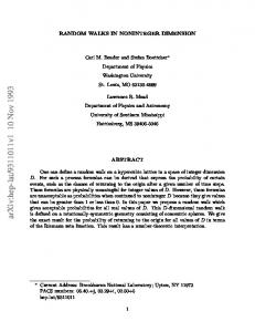
Consider the configuration whose motion controls satisfy for every 0 ≤ j ≤ J, for some J ≥ Jω , ( ( 1 if j = 1, Jω , Jω + 1; 1 if j ≤ Jω + 1; vj = ˙ (11) uj = ˙ 0 otherwise; 0 otherwise. Theorem 9. Let ω ∈ (0, π) and consider the configuration corresponding to the controls defined in (11). Then there exists a circle O sharing with the finger three contact points c1 , cJω and cJω +1 and satisfying (C) if and only if ρ < 2 + tan(ω(Jω − 1)/2) cot(ω/2).
(12)
If moreover ωJω 6= π then (12) also implies (SC).
0.2
-0.2
-0.1
0.1
0.2
-0.2
-0.4
0.2
-0.6
-0.4
-0.2
0.2
0.4
0.6
-0.2
-0.6 -0.4
-0.8
(a) ω = 2π/5
-0.6
(b) ω = 2π/8
Figure 6. Configurations associated to the controls defined in (11) and related inscribed circles O. Proof. Let J ≥ Jω and note that (11) implies that the extended phalanxes of the resulting configuration are the first one and every phalanx between the Jω -th and J-th ones. Moreover all phalanxes between the Jω + 1-th and the last belong to the same line, because their rotation controls are constantly 0. Hence we may construct a circle O tangent to the prolongations of these phalanxes. In particular, in Figure 6 are represented two possible scenarios: if Jω ω 6= π (see Figure 6.A) then by construction the prolongations of the phalanxes form a triangle and we set O as the inscribed circle of this triangle. Note that the tangency points c1 , cJω and cJω +1 are indeed contact points (namely they belong to the phalanxes and not to their prolongations) then by construction (SC) is satisfied. If otherwise Jω ω = π, then every extended phalanx but the second one is parallel to the first phalanx, see Figure 6.B. In this case we set O as the (unique) circle tangent to three
14
ANNA CHIARA LAI AND PAOLA LORETI
distinct extended phalanxes: in particular, it is the circle inscribed in the rhombus whose edges are as long as the Jω -th phalanx and whose internal angles are ω and π − ω. Note that in this case the only allowed direction l (namely the only unit vector satisfying (8)) is the one parallel to the first phalanx and with positive scalar product with the J-th phalanx. Also in this case call the resulting tangent points c1 , cJω and cJω +1 . It is left to show that (12) holds if and only if c1 , cJω and cJω +1 respectively belong to the first, to the Jω -th and to any subsequent phalanx. Remark that the Jω -th phalanx shares both its endpoints with other phalanxes, hence the prolongations we are considering only refer to the first and to the last phalanxes: by construction cJω is always tangent to the Jω -th phalanx. In particular we have that the distance between cJω and the Jω -th junction is lower than the length of the Jω -th phalanx: 1 (13) | x1 − cJω |≤ Jω . ρ Now, c1 belongs to the first phalanx if and only if 1 (14) | x1 − c1 |≤ ρ where x1 is the position of the first junction and ρ1 is the length of the first phalanx. Similarly cJω +1 belongs to a phalanx if and only if 1 (15) | xJω − cJω +1 |< Jω ρ (ρ − 1) indeed the right-hand side of the above inequality is the upper bound of the length of a finite sequence of adjacent phalanxes. A classical result in plane geometry states that if we consider two consecutive edges of a polygon admitting an inscribed circle, then the distances between the related tangent points and the common vertex are equal (see Figure 7). In our case this implies, together with (13), 1 (16) | x1 − c1 |=| x1 − cJω |< . ρ Similarly we may rewrite (15) as follows (17)
| xJω − cJω |