project funding of Huawei Technologies, China. The authors are with the Department of Electronic and Computer Engineer- ing, Hong Kong University of ...
566
IEEE JOURNAL ON SELECTED AREAS IN COMMUNICATIONS, VOL. 25, NO. 3, APRIL 2007
Robust Joint Interference Detection and Decoding for OFDM-Based Cognitive Radio Systems With Unknown Interference Tao Li, Wai Ho Mow, Senior Member, IEEE, Vincent K. N. Lau, Senior Member, IEEE, Manhung Siu, Senior Member, IEEE, Roger S. Cheng, Member, IEEE, and Ross D. Murch, Senior Member, IEEE
Abstract— Cognitive radio technology facilitates spectrum reuse and alleviates spectrum crunch. One fundamental problem in cognitive radio is to avoid the interference caused by other communication systems sharing the same frequency band. However, spectrum sensing cannot guarantee accurate detection of the interference in many practical situations. Hence, it is crucial to design robust receivers to combat the in-band interference. In this paper, we first present a simple pilot aided interference detection method. To combat the residual interference that cannot be detected by the interference detector, we further propose a robust joint interference detection and decoding scheme. By exploiting the code structure in interference detection, the proposed scheme can successfully detect most of the interfered symbols without requiring the knowledge of the interference distribution. Our simulation results show that, even without any prior knowledge of the interference distribution, the proposed joint interference detection and decoding scheme is able to achieve a performance close to that of the maximum likelihood decoder with the full knowledge of the interference distribution. Index Terms— cognitive radio, OFDM, narrowband interference, interference detection, erasure decoding.
I. I NTRODUCTION
T
HE EXPLOSIVE growth of wireless services in recent years illustrates the huge and growing demand for the spectrum. Unfortunately, wireless spectrum is a very scarce resource. A promising solution to solve the predicament is the cognitive radio technology [1]. Cognitive radio technology allows spectrum reuse in various dimensions including space, frequency and time, so as to obliterate the spectrum and bandwidth limitations. It is expected that cognitive radio systems can sense its environment and then alter its transmission power, occupied frequency, modulation and other parameters to dynamically reuse the available spectrum. In an orthogonal frequency-division multiplexing (OFDM) based cognitive radio system, the transmitter may allocate the data transmission rate to the subcarriers adaptively according to the different channel conditions of the subcarriers. It may simply avoid transmission in the narrow/partial band interference jammed subcarriers to alleviate the destructive
Manuscript received February 1, 2006; revised September 30, 2006. This work was supported by the Hong Kong Research Grant Council under grant number HKUST6300/03E and the Wireless Regional Area Network (WRAN) project funding of Huawei Technologies, China. The authors are with the Department of Electronic and Computer Engineering, Hong Kong University of Science and Technology, Hong Kong (e-mail: {eelitao,eewhmow,eeknlau,eemsiu,eecheng,eermurch}@ee.ust.hk). Digital Object Identifier 10.1109/JSAC.2007.070407.
effect of the interference. Unfortunately, spectrum sensing is a challenging research problem and the current sensing techniques cannot guarantee accurate detection of the interference in many practical situations [2]. For example, when the interference is bursty, the transmitter may not be kept updated fast enough and, thus, may not know the existence of the interference in a microscopic time scale (e.g. packet level). Hence, the receiver is posed a challenge to detect the transmitted packet in the presence of unknown interference. Coding is essential to achieve an acceptable error rate performance. Optimal decoder in the maximum likelihood sense can be performed given the noise and interference distribution. However, the exact knowledge of the interference distribution is normally hard to obtain in reality. To avoid the requirement of accurate estimates of the interference power, suboptimal erasure decoders are considered in [3]-[5]. Such decoding schemes erase (ignore) the interference jammed signal in the decoding process and, thus, partially avoid the adverse effect of the interference. Although they do not require the knowledge of the interference power, they need to know the presence of the interference. In [6], the null symbols (zero symbols) are sent as pilots for the receiver to detect the interference. The null symbols, however, are system overheads and reduce the system throughput. A simple method to detect the interference is based on the magnitude variation of the consecutive received symbols in time or frequency domain [7]. The effectiveness of this method is reduced for high order modulation schemes or when the fading varies significantly. In [7] and [8], the interference is estimated based on the rough estimate of the transmitted data symbols. The accuracy of this method is limited by the erroneous estimates of the transmitted data. In this work, we first propose a simple and novel pilot aided interference detection scheme. The same pilot symbols can be utilized for channel estimation and timing synchronization and hence, it does not require additional resource. Moreover, the interference detection is independent of the channel fading estimates and thus, no channel estimation is needed for the interference detection. However, since the pilots are normally placed sparsely, the interference cannot be fully detected in the subcarriers or time slots where no pilot exists. Hence, there will be residual undetected interference corrupted symbols in the packet even after the pilot aided interference detection process. One example is the Bluetooth interference to the
c 2007 IEEE 0733-8716/07/$25.00 �
LI et al.: ROBUST JOINT INTERFERENCE DETECTION AND DECODING FOR OFDM-BASED COGNITIVE RADIO SYSTEMS
Fig. 1.
Block diagram of a coded OFDM system.
567
function µ. The M -ary symbol sequence (x1 , x2 , ..., xN/m ) is then mapped to OFDM symbols by the inverse discrete Fourier transform (IDFT). Each OFDM symbol is appended by a cyclic prefix that is set to be longer than the delay spread of the multipath fading channel. At the receiver, by removing the cyclic prefix and performing discrete Fourier transform (DFT), the effective channel for each subcarrier becomes flat fading. In this work, we consider slow mobility communication environments and assume that the fading is unchanged during each packet. Due to the coexistence of other communication systems, part of the subcarriers may be jammed by interference. The kth received symbol yk (k = 1, 2, ..., N/m) after the DFT can be represented as yk = αk xk + nk ,
WLAN. The IEEE 802.11g WLAN system [9] operates in the same frequency band as the Bluetooth system [10], which is a narrowband frequency-hopping system. For a typical 200µs long WLAN packet, the probability of collision with a Bluetooth packet is more than 20% [7]. Since the frequencyhopping rate of Bluetooth is relatively high, it is not easy for the WLAN to sense the presence of the Bluetooth transmissions. Moreover, the Bluetooth traffic is bursty since it only transmits data during the first 366µs of each 625µs time slot. It is likely that the Bluetooth data packet may only collide with the data part of the WLAN packet without interfering the pilot symbols. In such situations, the pilot aided interference detection is unable to detect the presence of the interference. To combat the undetected residual interference in the packet, we further propose a robust joint interference detection and decoding scheme without requiring any pilot or any knowledge on the interference. Since the interference detection exploits the code structure, it effectively detects almost all the interference jammed symbols and is able to achieve a performance close to that of the optimal maximum likelihood decoder with the full knowledge of the interference distribution. Furthermore, methods to reduce the decoder complexity are also presented. With the complexity reduction techniques, the average additional complexity relative to the conventional decoding scheme can be small in many practical situations. The remainder of this paper is organized as follows. The system model is introduced in Section II. In Section III, the pilot aided interference detection scheme is presented. The robust joint interference detection and decoding scheme is introduced in Section IV. The complexity reduction methods are presented in Section V. The performance of the proposed decoding scheme is analyzed in Section VI. Finally, simulation results are presented in Section VII and the conclusions are drawn in Section VIII. II. S YSTEM M ODEL We consider the coded OFDM system as illustrated in Fig. 1. The coding scheme is the bit-interleaved coded modulation [11] that has been widely adopted in many OFDM based standards like IEEE 802.11, 802.16 and 802.22. The information sequence is first convolutionally encoded. The length-N codeword c = (c1 , c2 , · · · , cN ) is then bit-wise interleaved. Every m-tuple of the interleaved codeword is mapped to an M -ary (M = 2m ) symbol in the signal set χ based on a mapping
(1)
where αk is the Rayleigh fading factor and nk is the additive channel noise. Each noise sample is generated by either 2 in each complex background Gaussian noise (with variance σG dimension) or background noise plus interference. Although the proposed interference detection and decoding algorithms can be applied to any kind of interference distribution, we consider Gaussian distributed interference (with variance σI2 in each complex dimension) to facilitate the discussion. The conventional decoding scheme contains a demodulator, a deinterleaver and a Viterbi decoder [11]. For each received symbol yk , the demodulator calculates the metric for all the m bits c�i = b (b = 0, 1; i = 1, 2, ...m) that correspond to the kth symbol as λ(c�i = b) = log p(c�i = b|yk ) ∝ log
� xk ∈χib
=
min
xk ∈χib
p(yk |xk ) ≈ maxi log p(yk |xk ) xk ∈χb
2
|yk − αk xk | + const, 2σk2
(2)
where χib = {µ (c�1 , · · · , c�i , · · · , c�m ) |c�i = b} is the signal subset with the ith bit c�i being equal to b. The decoding metric for each codeword c is the summation of the deinterleaved bit metrics, i.e., N � ψ0 (c) = λ(ci ) (3) i=1
The last expression in (2) is obtained by assuming that the noise is Gaussian distributed. The conventional decoding scheme assumes that the noise variance σk2 is a constant for all the symbols and can be dropped in the bit metric calculation. When narrowband interference exists, the noise variance is not a constant for all the subcarriers and dropping the noise variance σk2 in the bit metric results in metric mismatch. When the interference power is high, the mismatch problem can be serious. Knowing the interference jammed subcarriers and the power of the interference, the optimal decoder, in the maximum likelihood sense, weights each symbol differently depending on whether the symbol is hit by background Gaussian noise or interference. A reasonable alternative decoding methodology is to simply ignore or erase these jammed symbols in decoding and assume a constant noise variance for the unerased symbols [3]-[5]. Since the interference power
568
IEEE JOURNAL ON SELECTED AREAS IN COMMUNICATIONS, VOL. 25, NO. 3, APRIL 2007
is normally much larger than the background Gaussian noise power, the performance loss would be small by treating the jammed symbols as erasures. Such an erasure decoding approach avoids the requirement of knowing the interference power. The decoding accuracy then highly depends on the estimation accuracy of the interference positions. III. P ILOT A IDED I NTERFERENCE D ETECTION In this section, we propose a simple pilot aided interference detection technique for OFDM systems. To detect the presence of interference, this technique requires at least two pilot symbols in a given subcarrier spaced in time. This requirement is fulfilled in many OFDM based systems, such as IEEE 802.11g WLAN, in which the preamble consists of two known OFDM symbols. The basic idea is to design the pilot symbols in such a way that their summation/subtraction is zero. For example, the two pilot symbols, xp1 and xp2 , can be selected as the two signal points in the BPSK constellation such that xp1 + xp2 = 0. Since xp1 and xp2 undergo the same fading, when adding together the two corresponding received symbols, y1p and y2p , the terms containing the channel fading factor are cancelled out and only the noise terms remain in the summation. Hence, to detect the presence of the interference for a given subcarrier is to determine one of the two hypotheses H0
: R = |y1p + y2p | = |np1 + np2 |
H1
: R = |y1p + y2p | = |np1 + np2 + I1p + I2p | ,
(4)
where np1 , np2 are the and I1p , I2p are the
background Gaussian noise components interference corresponding to the two pilot symbols. The hypotheses can be determined based on H1
a threshold r∗ , i.e., R ≷ r∗ . H0
Suppose the noise components are independent. The norm |np1 + np2 | is Rayleigh distributed with the probability density function (pdf) [13] 2 r −r2 /4σG e (r ≥ 0), (5) pR (r|H0 ) = 2 2σG and the cumulative density function (cdf) FR (r|H0 ) = 1 − e−r
2
2 /4σG
(r ≥ 0).
(6)
Similarly, if the interference components are independent, then |np1 + np2 + I1p + I2p | is also Rayleigh distributed with 2 2 2 the pdf pR (r|H1 ) = 2 σ2 r+σ2 e−r /4(σG +σI ) and the cdf ( G I) 2 2 2 FR (r|H1 ) = 1 − e−r /4(σG +σI ) . With the a priori knowledge of the interference statistics, the decision on the hypotheses can be made based on the loglikelihood ratio as pR (r|H0 )p(H0 ) H0 ≷ 0. (7) log pR (r|H1 )p(H1 ) H1 The corresponding decision threshold r∗ can be obtained as ⎧ � � � 2 2 ⎪ 2σG ⎪ 2 + σ 2 ) log 1−δ + log σG +σI ⎪ (σ 2 ⎪ G I σ δ σ I ⎨ G σ2 +σ2 r∗ = , if 0 ≤ δ ≤ 2σG2 +σI2 ⎪ ⎪ G I ⎪ ⎪ σ2 +σ2 ⎩ 0 , if 2σG2 +σI2 < δ ≤ 1 G I (8)
where δ is the probability of the randomly arrived interference. The decision threshold in (8) requires the knowledge of the interference statistics, which may be unavailable in reality. In such situations, the decision threshold can be determined based solely on the background Gaussian noise variance for a given false alarm probability pf according to (6), namely r∗ = 2σG log(1/pf ). The threshold should be set large enough to maintain a reasonably small false alarm probability. For a given threshold r∗ , the probability of missed detection of the interference is given by δFR (r∗ |H1 ). The missed detection probability gets smaller for low interference arrival probability or high interference power. The main advantage of this pilot aided interference detection scheme is its simple implementation based on the existing pilot symbols dedicated for channel estimation. However, it suffers from the same problem as any other pilot aided detection schemes. If the interference starts in the middle of the packet or exists in the subcarriers where no pilot is assigned, then the pilot based approach will fail to detect the interference. Therefore, in the following sections, we propose robust decoding techniques to combat the undetected interference. IV. ROBUST D ECODING T O C OMBAT U NDETECTED I NTERFERENCE In this section, we propose a robust decoding scheme to combat the undetected interference. Specifically, the decoder jointly performs erasure marking and decoding and is able to erase the interference jammed symbols automatically during the decoding process. The idea of joint erasure marking and decoding is conceptually similar to the robust speech recognition algorithm in [14] [15] and was originally proposed for channel decoding in the presence of impulsive noise in [16] (c.f. the journal version [17]). The decoding process is mainly composed of two steps. First, for a maximum number of K bits to be erased, find the K + 1 most likely codewords with each codeword corresponding to a particular number k (0 ≤ k ≤ K) of erasures. In the second step, the sufficient number of erasures is determined and the corresponding codeword is selected from the K + 1 candidates as the output codeword. The second step determines the number of erasures while the first step determines the positions of the erasures. For k erasures, the decoder jointly finds the most likely codeword and the most likely k erasure positions. Specifically, the decoding metric for codeword c with k erasures is defined as N � λ(ci ), (9) ψk (c) = min Ω∈Λ
i=1,i∈Ω /
where Λ represents the set of all possible k bit positions in the codeword. The metric in (9) involves searching all possible k erasure positions for each codeword c. For convolutional code, the minimization problem can be solved by searching for the shortest path in a product trellis that is built based on the erasure trellis and the bit trellis of the code [17]. To build the erasure trellis, we first introduce the erasure indicator and erasure counter. The erasure indicator for the ith bit is represented by the binary valued symbol ei which takes the value zero if the ith bit is erased and the value one
LI et al.: ROBUST JOINT INTERFERENCE DETECTION AND DECODING FOR OFDM-BASED COGNITIVE RADIO SYSTEMS
Fig. 2. (a) Erasure trellis for zero and one erasure. (b) Bit trellis for the rate-1/2 2-state convolutional code. States a and b are the original code trellis states. States c, d, e and f are the inserted states. (c) Product trellis for the rate-1/2 2-state convolutional code with zero and one erasure.
otherwise. The erasure counter εi counts the total number of bits that are marked as erasures from the beginning up to the ith bit. The erasure indicator sequence as well as the counter sequence can be represented by the erasure trellis, with the erasure counter εi labelling the states and the erasure indicator ei labelling the branches. Each path in the trellis corresponds to one possible erasure indicator sequence. Supposing that the total number of bits to be erased is at most K, the erasure trellis contains K + 1 states, i.e., εi ∈ {0, 1, ..., K}. As an example, Fig. 2 (a) shows the trellis for K = 1. The bit trellis of the code is a simple extension of the convolutional code trellis by inserting L − 1 (with L being the number of code bits per trellis branch) intermediate states between any two connected states in adjacent trellis levels. Each branch in the bit trellis corresponds to one code bit. The bit trellis is equivalent to the original code trellis in a sense that they represent the same set of codewords. The product trellis can then be obtained by combining the bit trellis and the erasure trellis. Suppose the ith level of the bit trellis consists of Ni states qi1 , qi2 , ..., qiNi and the ith level ˆi states ε1 , ε2 , ..., εNˆi . The of the indicator trellis consists of N i i i product of the two trellises is a trellis whose�level i consists ˆi states numbered by the pairs q j , εjˆ , j = 1, ..., Ni , of Ni N i �
i �
ˆ l l ˆ jˆ = 1, ..., Ni . Two states qi−1 , εi−1 and qij , εjiˆ at adjacent trellis levels are connected by a branch labeled by the pair l (ci , ei ) if and only if the two states, qi−1 and qij in the bit trellis, are connected by a branch labeled by ci , and the two ˆ states, εli−1 and εjiˆ in the erasure trellis, are connected by a branch labeled by ei . The corresponding branch metric is defined as λ� (ci , ei ) = λ(ci ) · ei . (10) The path metric is then the summation of the branch metrics. Each path in the product trellis corresponds to one distinct codeword and erasure indicator sequence. The paths ending at the state with its erasure counter value being k (0 ≤ k ≤ K) correspond to the codewords with k erasures. As an example, Fig. 2 illustrates the procedure of forming the product trellis for the rate-1/2 2-state convolutional code
569
with zero and one erasure. Fig. 2 (a) shows the erasure trellis. In Fig. 2 (b), an intermediate state is inserted between each pair of connected code states such that the bit trellis is formed. The product trellis can then be obtained based on the bit trellis and the erasure trellis as shown in Fig. 2 (c). Given the product trellis, the most likely path can be obtained by performing the Viterbi algorithm. Once the most likely codewords with 0, 1, 2, · · · , K erasures, respectively, are obtained, the sufficiency criterion is applied to determine the sufficient number of erasures and select the output codeword from the candidate codewords. An outer error checking code, like the CRC code, can be applied as the sufficiency criterion. The candidate codeword satisfies the error checking condition is selected as the output codeword. Without an outer error checking code, we can use a self-contained path metric difference (PD) criterion proposed in [17]. This criterion is performed by evaluating the metric difference between two successive most likely codewords with k − 1 and k erasures for k = 1, 2, · · · . The more erasures marked, the smaller the metric of the most likely codeword. After all the bits corrupted by the high amplitude interferences are erased, erasing one more bit results in a relatively smaller metric difference. If the metric difference of the codewords with k − 1 and k erasures is less than a pre-set threshold ηDec (ηDec ≥ 0), then k − 1 erasures are determined to be sufficient and the most likely codeword with k − 1 erasures is selected as the output codeword. V. D ECODER C OMPLEXITY R EDUCTION The decoder complexity can be estimated by counting the number of operations. For a rate-1/2 code, the computational complexity for finding one more codeword with an additional erasure is about two to three times that of the Viterbi algorithm. For a code with a large memory size, the complexity of the decoder is much higher than that of the demodulator. Therefore, the overall decoding complexity is dominated by the decoder and is linearly increasing with the number of erasures. To decode a received sequence with a large number of interference jammed symbols, the decoding complexity can be very high. In this section, we present two complexity reduction techniques. A. Demodulator Based Erasure Marking To relieve the computational burden of the decoder, we can exploit the demodulator to erase part of the interference jammed symbols before decoding. The bit metric measures the distance of the received signal to the signal points in the signal constellation and finds the smallest as the metric. If the noise is low, the received signal is close to the transmitted signal point. With a high amplitude interference, it is likely that the received signal is far from all of the signal points in the constellation. Therefore, by comparing the bit metric with a preset threshold ηDem , the bit erasure can be declared. Practically, the threshold may be determined based on the background Gaussian noise power, irrespective of the channel fading. The geometric representation of the demodulator based erasure marking for 16QAM is shown in Fig. 3. The demodulator is able to erase the interference jammed bits as
570
IEEE JOURNAL ON SELECTED AREAS IN COMMUNICATIONS, VOL. 25, NO. 3, APRIL 2007
Fig. 4. Block diagram of the sequential implementation of the joint erasure marking and decoding scheme.
Fig. 3. Geometric representation of the demodulator based erasure marking. The received signals fall outside the closed area are erased.
long as the received signal falls into the region outside the closed area. The following theorem indicates that by setting ηDem ≥ ηDec the set of erasures marked by the demodulator is a subset of those marked by the decoder with PD criterion and an unconstrained number of erasures. Since marking erasure at the demodulator requires little additional computational complexity, applying the demodulator based erasure marking scheme with threshold ηDec reduces the overall complexity without introducing any performance loss. Theorem 1: Let ΩDec be the set of bits erased by the decoder with the path metric difference criterion with threshold ηDec and an unconstrained number of erasures and ΩDem = {cj | min λ(cj = b) > ηDem , j = 1, 2, ..., N } be the set of b=0,1
bits erased by the demodulator with threshold ηDem . Then ΩDem ⊆ ΩDec if ηDem ≥ ηDec . Proof: Suppose the output codeword selected by the PD criterion with threshold ηDec is ck with k erasures. Let the most likely codewords with k − 1 and k + 1 erasures be ck−1 and ck+1 respectively. Since ck is selected as the output codeword, it is true that ψk−1 (ck−1 ) − ψk (ck ) > ηDec , and ψk (ck ) − ψk+1 (ck+1 ) < ηDec .
(11)
The set ΩDem includes all the bits with minimum metric larger than ηDem . To prove ΩDem ⊆ ΩDec for ηDem ≥ ηDec , it is sufficient to prove that all the bits with a metric larger than ηDec have already been erased by the decoder in obtaining the output codeword ck with k erasures. In fact, if there exists a bit with metric λ(cj ) > ηDec in ck after marking k erasures, then erasing the bit cj results in a smaller metric than ψk+1 (ck+1 ) with k + 1 erasures because of (11), i.e., ψk+1 (ck ) < ψk+1 (ck+1 ). This contradicts the assumption that ψk+1 (ck+1 ) is the smallest among all the codewords with k+1 erasures. Thus, all the bits cj with metric min λ(cj = b) > b=0,1
ηDec have already been erased by the decoder in obtaining the output codeword. This proves ΩDem ⊆ ΩDec if ηDem ≥ ηDec . The demodulator is able to erase part of the interference jammed symbols but may also miss a significant amount of jammed symbols. For example, suppose the signal at the point
a in Fig. 3 is transmitted and the signal around the point b is received. Although the interference amplitude is quite high, the demodulator cannot distinguish it because the received signal is close to a signal point in the constellation. These undetectable interference will then be handled by the decoder. B. Sequential Implementation For each interference jammed M -ary symbol, the decoder has to mark m bit erasures to eliminate the interference. The decoder complexity is higher for a higher order modulation, even though the interference distribution is unchanged. A more efficient approach is to exploit the bit-to-symbol association and mark symbol erasures based on the bit erasures. Specifically, the decoder only performs a single bit erasure marking during each decoding pass based on the single erasure product trellis and feeds back the most recently found bit erasure position to the demodulator as demonstrated in Fig. 4. The demodulator then marks the corresponding symbol as a new erasure (in addition to all of the symbol erasures marked in previous decoding passes) and updates the bit metric for the next decoding pass. The decoding process is repeated until the output codeword is found. For each decoding pass, the demodulator does not need to compute the bit metric again. It only needs to rewrite the bit metrics that correspond to the marked symbol as zeros. Besides exploiting the bit-to-symbol association, the erasure marker may also take advantage of the interference property. For example, if the codeword is sent through multiple OFDM symbols in a packet, one jammed subcarrier may result in multiple jammed M -ary symbols. In such cases, all the symbols correspond to the same subcarrier should also be erased if any one of the symbols in this subcarrier is marked as an erasure. Exploiting the a priori knowledge of such relations can not only reduce the decoder complexity but also improve the decoding performance. This serialized implementation enables the decoder to stop once a codeword is found to satisfy a certain sufficiency criterion and significantly reduces the decoding complexity. In fact, during each decoding pass, the zero erasure and one erasure codewords can also be obtained sequentially. It can be observed in Fig. 2 (c) that to find the most likely codeword without erasure, only the first layer (with erasure counter εi = 0) of the product trellis is involved. Therefore, it can be obtained prior to the codeword with one erasure. In the situations when there is no narrowband interference, the decoder may only find the most likely codeword without erasure if it satisfies the error checking and does not go through any further decoding process. In such situations, it becomes similar to the conventional Viterbi decoder with the
LI et al.: ROBUST JOINT INTERFERENCE DETECTION AND DECODING FOR OFDM-BASED COGNITIVE RADIO SYSTEMS
571
−3
outer error detecting code based sufficiency criterion. That is to say, the proposed decoder is able to adapt to the dynamically changing interference condition and introduces little additional complexity relative to the conventional decoder when there is no interference.
4
x 10
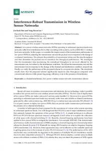
Jam=3 Jam=5 Jam=7
3.5 3 2.5
The exact performance analysis of the proposed decoding scheme is very complicated because the erasures are codeword dependent. Nevertheless, we provide a simplified analysis by assuming all the interference jammed symbols are successfully erased by the decoder. With this idealized assumption, the performance is equivalent to that of the Viterbi decoder in Gaussian noise channel with erasures. The random bit-wise interleaver maps the jammed symbol positions randomly into the bit positions in the codeword. Supposing the interference arrival rate is δ, the effective channel between the convolutional encoder and decoder can be modeled as a Gaussian noise channel with random bit erasures of probability δ when the number of subcarriers to transmit the data packets is not too small. Without any erasure, the bit error rate (BER) of the bitinterleaved coded modulation with a rate-kc /nc convolutional code is given by [11] Pb ≤
∞ 1 � W (d)fµ,χ (d), kc
(12)
d=dmin
where W (d) is the total input weight of error events with Hamming weight d, dmin is the minimum Hamming weight of the code and fµ,χ (d) denotes the pairwise error probability (PEP) of two codewords at a Hamming distance d and is dependent on the bit-to-symbol labeling map µ and the signal set χ in use. With erasures, the original distance d between the two codewords can be reduced to d� (0 ≤ d� ≤ d) with d d−d � � probability d−d� δ (1 − δ)d . The term W (d)fµ,χ (d) in d
d−d� � � d (12) becomes (1 − δ)d W (d)fµ,χ (d� ) corred−d� δ d� =0
spondingly. Summing all the terms with distances d = dmin to ∞, the average union bound can be obtained as [18] Pb ≤ � (d) = where W
1 kc
∞ �
� (d)fµ,χ (d), W
BER
VI. P ERFORMANCE A NALYSIS
2 1.5 1 0.5 0
0
10
20
30
40
50
60
threshold/sigma2
Fig. 5. Effect of the decoding threshold ηDec on the BER performance with SNR=12dB, SIR=0dB and various numbers of jammed subcarriers.
each side of xk . Specifically, x �k and x ��k can be selected as sk the closest signal points to xk in χeck on each side of xk , respectively. If there is no signal point belongs to χseckk on either side, then x ��k is assumed to be an imaginary signal point that is at infinite distance from xk . The PEP upper bound conditioned on the labeling positions s can be derived by averaging over all possible transmitted symbol subsequence x ∈ χsc as � P (c → � c | s) = P
d �
λ(� ck ) ≤
k=1
≤
2−d(m−1)
� �
d �
� λ(ck )
k=1
P (x → z),
(14)
x∈χsc z∈Zx
where the set Zx consists of 2d length-d sequences, with the kth element of each being either x �k or x ��k . The PEP can then be obtained by unconditioning (14) with respect to s over the md sequences of labeling positions as fµ,χ (d)
= =
(13)
Es [P (c → � c | s)] � � � −d −d(m−1) m 2 P (x → z).(15) x∈χsc z∈Zx
s
d=0
∞ � 1−δ �d � i i δ d W (i)δ is the equivalent weight i=d
of error events with Hamming weight d after erasure. The PEP fµ,χ (d) can be analyzed following the method in [11] and [12]. Let c and � c denote the subsequences of the transmitted codeword and its erroneous estimate consisting of the d bits where they differ. Let the labeling positions of these d bits be specified by the vector s. That is, the bit ck (1 ≤ k ≤ d) corresponds to the sk th (1 ≤ sk ≤ m) labeling position of the M -ary symbol xk . For M -QAM with Gray mapping, there are two competing symbols of each transmitted symbol xk ∈ χsckk that are relevant to the calculation of fµ,χ (d) [12]. Counting the error probability of xk to the two symbols respectively leads to an union bound to fµ,χ (d). These two ��k , belong to the set χseckk and are lined in symbols, x �k and x the same row or column in the constellation as xk , one on
The PEP can be calculated efficiently by applying the Laplace transform method [11]. That is, fµ,χ (d) =
1 2πj
�
a+j∞
a−j∞
[ψ(s)]d
ds s
(16)
with ψ(s) =
m � 1 ��� Φ∆(x,ex) (s) + Φ∆(x,ex� ) (s) , m m2 i=1 i
(17)
x∈χ0
where x � and x �� are the two competing symbols of x and Φ∆(x,ex) (s) is known to be 1+s(1−sσ12 )|x−ex|2 for Gaussian G noise channel with Rayleigh fading. The symbol a in (16) is a positive real number within the convergence region of Φ∆(x,ex) (s).
572
IEEE JOURNAL ON SELECTED AREAS IN COMMUNICATIONS, VOL. 25, NO. 3, APRIL 2007
−3
2
x 10
−1
10
Conventional JED MLD
SIR=−10 SIR=−5 SIR=0
1.8 1.6
−2
1.4
10 BER
BER
1.2 1 0.8
−3
10
0.6 0.4 0.2
−4
0
10
20
30
40
50
60
70
80
10
90
0
threshold/sigma2
Fig. 6. Effect of the decoding threshold ηDec on BER performance with SNR=12dB, 5 jammed subcarriers and various SIR values.
4 6 8 Number of Jammed Subcarriers
10
12
Fig. 7. BER of the joint erasure marking and decoding scheme with SNR=12dB, SIR=0dB and various numbers of jammed subcarriers.
−1
10
VII. S IMULATION R ESULTS
Conventinal JED MLD −2
10 BER
Throughout the simulations, the rate-1/2 64-state convolutional code and 16QAM with Gray mapping is considered. The baseline decoding schemes for comparison are the conventional decoder designed for AWGN and the optimal maximum likelihood decoder (MLD) that knows exactly the jammed subcarriers as well as the interference power in each subcarrier and applies the exact noise variance σk2 to each symbol in calculating the bit metric in (2). The proposed joint erasure marking and decoding scheme is denoted as JED in the figures. In fact, the proposed decoding scheme reduces to the conventional one by setting ηDem = ∞ and ηDec = ∞ when an outer error checking code exists. When there is no interference, the three decoding schemes are effectively equivalent. In the simulations, each packet contains exactly one codeword and all the symbols in the jammed subcarriers are erased if any bit in the subcarrier is marked as an erasure. The threshold of the pilot aided interference detector is set to be 5σG . For the CRC based sufficiency criterion, the generator polynomial of the CRC code is chosen to be 435(octal). Zeros are padded at the end of the CRC codeword such that the convolutional code is terminated. Two BPSK pilot symbols with the same power as the data symbols are used for each subcarrier. In the simulations from Fig. 5 to Fig. 11, we assume that each codeword is mapped to 10 OFDM symbols each containing 200 subcarriers. The fading at each subcarrier is independent. It is a reasonable assumption for OFDM access (OFDMA) systems, where each user is assigned a subset of subcarriers that are normally not contiguous. Figs. 5 - 8 evaluate the effect of the threshold ηDec of the PD sufficiency criterion on the error rate performance. The maximum allowed number of erasures is set to be sufficiently large. The threshold of the demodulator is ηDem = ∞ which means the demodulator does not mark erasure based on the bit metric. The fading factor is assumed to be perfectly known at the receiver. Fig. 5 and Fig. 6 evaluate the BER 2 . In Fig. 5, various performance as a function of ηDec /σG numbers of jammed subcarriers are evaluated under the signalto-background Gaussian noise power ratio SNR=12dB and
2
−3
10
−4
10 −10
−5
0
5
SIR(dB)
Fig. 8. BER of the joint erasure marking and decoding scheme with SNR=12dB, 5 jammed subcarriers and various SIR values.
the signal-to-interference power ratio SIR=0dB. In Fig. 6, five subcarriers are jammed with various interference power under SNR=12dB. It can be seen that the best error rate performance can be achieved by setting the threshold properly. The best threshold value does not change significantly for different numbers of jammed subcarriers or different interference power. In fact, it is only strongly dependent on the background Gaussian noise power and can be determined offline. Therefore, the PD criterion is robust to various interference conditions and is feasible in practice. For the rest of the simulations, the threshold of the PD criterion is set to 2 . be ηDec = 24σG Fig. 7 shows the BER performance of the conventional decoder, the maximum likelihood decoder (MLD) and the proposed joint erasure marking and decoding scheme (JED) with SIR=0dB, SNR=12dB and various numbers of interference jammed subcarriers. Fig. 8 shows the BER performance of the three decoding schemes with SNR=12dB, five jammed subcarriers and various SIR values. It can be observed from Fig. 7 and Fig. 8 that JED significantly outperforms the conventional one and effectively attains the optimal decoding performance for various numbers of jammed subcarriers with
LI et al.: ROBUST JOINT INTERFERENCE DETECTION AND DECODING FOR OFDM-BASED COGNITIVE RADIO SYSTEMS
JED MLD Conventional+Ideal ID Bound: Conventional+Ideal ID
−2
10
−3
573
0
10
10
−1
PER
BER
10 −4
10
−5
10
Conventional ID+Conventional Demod+Conventional ID+Demod+Conventional JED MLD
−2
10 −6
10
10
−3
11
12
13 14 SNR(dB)
15
16
17
Fig. 9. Performance bound and the simulated BER of the proposed decoding scheme, the MLD and the conventional decoder with ideal interference detection.
a wide range of interference power. The BER increases as the number of jammed symbols increases and remains almost unchanged as the interference power increases. When the interference power is lower than the signal power, it is more difficult for the JED to identify the interference and, thus, the gap between the JED and MLD becomes slightly larger. Such situations, however, are not the dominating situations that limit the system performance. In fact, even the conventional decoder achieves an acceptable performance under such situations. In Fig. 9, the performance analysis in Section VI is compared with the simulation results. The interference is randomly generated for each subcarrier with a probability of 0.04 and uniformly distributed power within [-20dB,10dB]. The performance of the JED, the MLD and the conventional decoder with ideal interference detection (ID) and perfect erasure of the interference are quite close to each other. The MLD with the knowledge of both the interference position and power performs the best. With perfect erasure of the interference, the conventional decoder performs in between the JED and the MLD. This simulation shows the JED without requiring any knowledge on the interference is able to correctly erase almost all the interference jammed symbols. The BER performance analysis for the conventional decoder with perfect erasure can be used as a reasonably good approximation of the performance of JED. Besides BER, the packet error rate (PER) is also an important measure of the system performance. In the rest of the simulations, the PER performance will be evaluated. To show the performance gain by exploiting the code structure, the joint erasure marking and decoding scheme is compared with the separate counterparts in Fig. 10. The separate erasure markers are the pilot aided interference detector (ID) proposed in Section III and the demodulator based erasure marker (Demod) proposed in Section V-A with ηDem = ηDec . Both the interference detector and the demodulator are able to erase part of the interference jammed symbols based on the channel output and are suitable for the applications with stringent complexity and delay constraint. The joint approach outperforms the two separate approaches significantly and effectively
10
10
11
12
13 SNR(dB)
14
15
16
Fig. 10. PER of the proposed interference detection and decoding schemes with perfect channel fading estimation.
0
10
−1
10
PER
−7
10
Conventional ID+Conventional ID+Demod+Conventional JED JED (feedback) MLD (perfect channel)
−2
10
−3
10
9
10
11
12
13
14
15
16
17
18
SNR(dB)
Fig. 11. PER of the proposed interference detection and decoding schemes with practical channel estimation.
achieves the optimal decoding performance in the whole SNR range under evaluation. The gap of the separate approaches to the joint approach demonstrates the performance gain by exploiting the code structure. The performance gain becomes larger for higher SNR. By exploiting the code structure, JED is able to almost fully eliminate the interference jammed symbols. The proposed interference detection and decoding schemes are evaluated in the presence of channel estimation errors in Fig. 11. The channel estimator adopted is the frequency domain least square (LS) estimator with two pilots per subcarrier. The channel is estimated as 0.5 (y1p /xp1 + y2p /xp2 ). It can be observed by comparing with Fig. 10 that the performance loss of JED due to imperfect channel estimation is around 2dB. With both the pilot aided interference detection and the demodulator based erasure marking, the average decoder complexity with the PD criterion is about 4 times that of the conventional Viterbi decoder at SNR=15dB. When the CRC based sufficiency criterion is applied together with the PD criterion (i.e., decoding terminates if any one of the criterion is satisfied), then the average complexity is only about 1.5 times that of the Viterbi decoder. The complexity further decreases
574
IEEE JOURNAL ON SELECTED AREAS IN COMMUNICATIONS, VOL. 25, NO. 3, APRIL 2007
either case, the average computational complexity of JED is less than twice of the Viterbi decoder. With such a marginal complexity increase, the proposed decoding scheme is able to approach the optimal decoder performance regardless of the interference condition.
0
10
−1
PER
10
VIII. C ONCLUSION −2
10
−3
10
12
Conventional ID+Conventional JED MLD 14
16
18 SNR(dB)
20
22
24
Fig. 12. PER of the proposed interference detection and decoding schemes in WLAN with perfect channel fading estimation.
as SNR increases. It is worth mentioning that without the separate erasure markers, the performance of JED remains almost unchanged. However, the complexity and decoding delay are much larger. For example, the complexity is about 20 times higher than that of the Viterbi decoder at SNR=15dB. Therefore, the proposed separate erasure marking schemes are able to reduce the decoder complexity significantly and, thus, make the joint erasure marking and decoding a practical scheme. We can improve the channel estimation by exploiting the decoder output. If none of the candidate codeword passes the error checking test, then the decoder goes to the second decoding iteration and the codeword that satisfies the PD criterion is fed back for channel estimation. With the feedback, the frequency domain LS channel estimator is applied not only to the pilot symbols but also to the data symbols. It can be seen in Fig. 11 that around 1dB gain can be achieved by applying decision feedback. At SNR=15dB, only 4% packets go through the second iteration and thus, the average additional decoding complexity is marginal. Finally, we evaluate the proposed interference detection and decoding schemes in a typical IEEE 802.11g WLAN environment in Fig. 12. The channel taps are independent complex Gaussian random variables with an exponentially σ2 σ2 decaying power profile. That is, hk = N (0, 2k ) + jN (0, 2k ) (k = 0, 1, ..., 10) where σk2 = σ02 e−k and σ02 = 1 − e−1 . We assume the fading factor is perfectly known to the receiver. Each packet consists of 50 OFDM symbols and a total of 48 subcarriers are dedicated to data transport. The PD and CRC based sufficiency criteria are used together. The Bluetooth packets interfere with the WLAN packets for three consecutive subcarriers with SIR=0dB. The interference detector alleviates the catastrophic effect of the interference when the pilot symbols are hit by the Bluetooth interference. The proposed decoding scheme further improves the performance and pushes the performance to the MLD performance limit. Since the Bluetooth packets are transmitted in bursts, they may or may not collide with the pilot symbols of the WLAN packets. If they do not jam the pilots, then the pilot aided interference detector cannot detect the presence of the interference. In
We proposed a robust joint interference detection and decoding scheme for OFDM based cognitive radio systems with unknown interference. Without knowing the interference distribution, the proposed decoding scheme significantly outperforms the conventional decoding scheme and effectively achieves the performance of the MLD that exploits the perfect knowledge of interference statistics. The price is the increased computational complexity and decoding delay. With the proposed complexity reduction techniques and the aid of the pilot aided interference detection, we have shown by simulation that the additional complexity and delay is affordably small compared with the conventional decoding scheme. R EFERENCES [1] J. Mitola III and G. Q. Maguire, Jr., “Cognitive radio: making software radios more personal,” IEEE Pers. Commun., vol. 6, pp. 13–18, Aug. 1999. [2] D. Cabric, S. M. Mishra and R. W. Brodersen, “Implementation issues in spectrum sensing for cognitive radios,” in Proc. 38th Asilomar Conference on Signals, Systems and Computers, vol. 1, pp. 772–776, Nov. 2004. [3] K. K. Wong and T. O’Farrell, “Coverage of 802.11g WLANs in the presence of Bluetooth interference,” in Proc. IEEE International Symposium on Personal, Indoor and Mobile Radio Communications, vol. 3, pp. 2027–2031, Sep. 2003. [4] L. E. Aguado, K. K. Wong and T. O’Farrell, “Coexistence issues for 2.4GHz OFDM WLANS,” in Proc. Third International Conference on 3G Mobile Communication Technologies, pp. 400–404, May 2002. [5] J. N. Laneman and C. W. Sundberg, “Soft selection combining for terrestrial digital audio broadcasting in the FM band,” IEEE Trans. Broadcast., vol. 47, pp. 103–114, Jun. 2001. [6] K. Fazel, “Narrow-band interference rejection in orthogonal multicarrier spread-spectrum communications,” in Proc. Third Annual International Conference on Universal Personal Communications, pp. 46–50, Sep. 1994. [7] S. Vogeler, L. Broetje and K. D. Kammeyer, “Blind Bluetooth interference detection and suppression for OFDM transmission in the ISM band,” in Proc. 37th Asilomar Conference on Signals, Systems and Computers, vol. 1, pp. 703–707, Nov. 2003. [8] M. Ghosh and V. Gaddam, “Bluetooth interference cancellation for 802.11g WLAN receivers,” in Proc. IEEE International Conference on Communications, vol. 2, pp. 1169–1173, May 2003. [9] IEEE standard for information technology–telecommunications and information exchange between systems–local and metropolitan area networks–specific requirements Part II: wireless LAN medium access control (MAC) and physical layer (PHY) specifications, 2003. [10] Specification of Bluetooth System, Version 1.1, Feb. 2002. [11] G. Caire, G. Taricco and E. Biglieri, “Bit-interleaved coded modulation,” IEEE Trans. Inform. Theory, vol. 44, pp. 927–945, May 1998. [12] V. Sethuraman and B. Hajek, “Comments on “Bit-interleaved coded modulation”,” IEEE Trans. Inform. Theory, vol. 52, pp. 1795–1797, Apr. 2006. [13] J. Proakis, Digital communications, Fourth Ed., McGraw Hill, 2000. [14] M. Siu and A. Chan, “Robust speech recognition against packet loss,” in Proc. European Conference on Speech Comm. and Tech. 2001. [15] —–, “A robust Viterbi algorithm against impulsive noise with application to speech recognition,” IEEE Trans. Speech Audio Processing, Nov. 2006. [16] T. Li, W. H Mow and M. Siu, “A joint approach to erasure marking and Viterbi decoding for impulsive noise channels,” in Proc. IEEE Signal Processing Workshop on Signal Processing Advances in Wireless Communications, pp. 180–184, Jun. 2003.
LI et al.: ROBUST JOINT INTERFERENCE DETECTION AND DECODING FOR OFDM-BASED COGNITIVE RADIO SYSTEMS
[17] —–, “A joint approach to erasure marking and Viterbi decoding for unknown impulsive noise channels,” submitted to IEEE Trans. Wireless Commun.. [18] J. M. Geist and J. B. Cain, “Viterbi decoder performance in Gaussian noise and periodic erasure bursts,” IEEE Trans. Commun., vol. COM-28, No. 8, pp.1417–1422, Aug. 1980.
Tao Li received the B.S. degree in electronics and information science from Beijing University, Beijing, China, in 1998, with a minor in Economics. She received the M.Phil and Ph.D degrees in electrical and electronic engineering from the Hong Kong University of Science and Technology (HKUST), Hong Kong, in 2000 and 2006, respectively. She is currently a research associate in the department of ECE at HKUST. She is the recipient of the ISITA2002 Paper Award for Young Researchers. Her current research interests include cognitive radio technology, OFDM techniques, MIMO signal processing, CDMA multiuser detection, channel coding and signal detection techniques. Wai Ho Mow (S’89-M’93-SM’99) received his M.Phil. and Ph.D. degrees in information engineering from the Chinese University of Hong Kong in 1991 and 1993, respectively. From 1997 to 1999, he was with the Nanyang Technological University, Singapore. He has been with the Hong Kong University of Science and Technology since March 2000. He is also an Adjunct Professor of the Southwest Jiaotong University, Chengdu, China. His research interests are in the area of coding and communication theory with emphasis on signal design and detection techniques. He published one book and over 100 technical papers, among which he is the sole author of over 40. He coauthored a paper that received the ISITA2002 Paper Award for Young Researchers and supervised two final year projects that won the first-runner up prizes in the IEE Hong Kong YMS Project Competitions in 2002 and 2003, respectively. Dr. Mow was the recipient of the Croucher Research Fellowship (Hong Kong), the Humboldt Research Fellowship (Germany), the TAO Research Fellowship (Japan), the Tan Chin Tuan Fellowship (Singapore), and the Foreign Expert Bureau Fellowship (China). He was the chair of the Hong Kong Chapter of the IEEE Information Theory Society in 2005. He was the technical program co-chair of five conferences, and served numerous technical program committees, such as ICC, Globecom, ITW and ISITA. He was a guest editor of a special issue of the IEICE Transactions on Fundamentals in 2006. He has been a member of the Radio Spectrum Advisory Committee, Office of the Telecommunications Authority, Hong Kong S.A.R. Government since 2003. Vincent K. N. Lau (M’95-SM’01) obtained B.Eng (Distinction 1st Hons) from the University of Hong Kong (1989-1992) and Ph.D. from Cambridge University (1995-1997). He was with HK Telecom (PCCW) as system engineer from 1992-1995 and Bell Labs - Lucent Technologies as member of technical staff from 1997-2003. He joined the Department of ECE, Hong Kong University of Science and Technology (HKUST) as Associate Professor. At the same time, he is a technology advisor of HKASTRI, leading the Advanced Technology Team on Wireless Access Systems. His current research focus is on the robust cross layer scheduling for MIMO/OFDM wireless systems with imperfect channel state information, communication theory with limited feedback as well as cross layer scheduling for users with heterogeneous delay requirements.
575
Manhung Siu (M’88-SM’03) received the B.S. degree from Boston University, MA, in 1988, the M.S degree from California Institute of Technology, CA, in 1989, and the Ph.D degree from Boston University, MA, in 1998, all in electrical engineering. Between 1989-1998, he was a member of the Speech and Language Processing Department at BBN Technologies, where he worked on speaker clustering, word spotting and speech recognition. He is currently an assistant professor in the Electronic and computer Engineering Department at the Hong Kong University of Science and Technology. His research interests include pattern recognition, novel acoustic modeling, language modeling, speaker and language verification, confidence score estimation and speech technology for educational applications. Roger S. Cheng (S’85-M’91) received the B.S. degree from Drexel University, Philadelphia, PA, in 1987, and both the M.A. and Ph.D. degrees from Princeton University, Princeton, NJ, in 1988 and 1991, respectively, all in electrical engineering. From 1991 to 1995, he was an Assistant Professor in the Electrical and Computer Engineering Department of University of Colorado at Boulder. In June 1995, he joined the Faculty of Hong Kong University of Science and Technology (HKUST), where he is currently an Associate Professor in the Department of Electronic and Computer Engineering. He also held visiting positions with Qualcomm, San Diego, in the summer of 1995, and with Institute for Telecommunication Sciences, NTIA, Boulder, CO, in the summers of 1993 and 1994. He was the Director of the Center for Wireless Information Technology at HKUST from 1999 to 2001 and the Associate Director for the Consumer Media Center at HKUST. Dr. Cheng is the recipient of the Meitec Junior Fellowship Award from the Meitec Corporation in Japan, the George Van Ness Lothrop Fellowship from the School of Engineering and Applied Science in Princeton University, and the Research Initiation Award from the National Science Foundation. He has served as Editor in the area of Wireless Communications for the IEEE TRANSACTIONS ON COMMUNICATIONS, Guest Editor of the special issue on Multimedia Network Radios in the IEEE JOURNAL ON SELECTED AREAS IN COMMUNICATIONS, Associate Editor of the IEEE TRANSACTION ON SIGNAL PROCESSING, and membership chair for of the IEEE Information Theory Society. His current research interests include wireless communications and networks including MIMO, OFDM, CDMA, Resource allocations, digital implementation of communication systems, information theory, and coding. Ross D. Murch (S’85-M’87-SM’98) is a Professor of Electronic and Computer Engineering at the Hong Kong University of Science and Technology. His current research interests include MIMO antenna design, MIMO and cooperative systems, WLAN, B3G and Ultra-Wide-Band (UWB) systems for wireless communications. He has several US patents related to wireless communication, over 150 published papers and acts as a consultant for industry and government. In addition he is an editor for the IEEE Transactions on Wireless Communications, Technical Program Chair for the IEEE Wireless Communication and Networking Conference in 2007 and was the Chair of the Advanced Wireless Communications Systems Symposium at ICC 2002. He is also the founding Director of the Center for Wireless Information Technology at Hong Kong University of Science and Technology which was begun in August 1997. He is the program Director for the MSc in Telecommunications at Hong Kong University of Science and Technology. From August-December 1998 he was on sabbatical leave at Allgon Mobile Communications (which manufactured 1 million antennas per week in 1998), Sweden and AT&T Research Labs, NJ, USA.