Feng Lin, Ben M. Chen, Tong H. Lee. Department of Electrical & Computer Engineering, National University of Singapore. 4 Engineering Drive 3, Singapore ...
13-4
MVA2009 IAPR Conference on Machine Vision Applications, May 20-22, 2009, Yokohama, JAPAN
Robust Vision-Based Target Tracking Control System for an Unmanned Helicopter Using Feature Fusion Feng Lin, Ben M. Chen, Tong H. Lee Department of Electrical & Computer Engineering, National University of Singapore 4 Engineering Drive 3, Singapore 117576 {linfeng, bmchen, eleleeth}@nus.edu.sg
Abstract
The main contribution of this paper is to present a novel framework to realize robust vision-based ground target detection for a UAV, and combine the vision target detection with the control strategy to achieve vision-based tracking in real scenes. The proposed target detection algorithm fuses geometry, color and motion features which are described by moment invariants, a color histogram, and motion estimation of a Kalman filter respectively. A finite-state machine coordinates the work of decision making under the Bayes framework by choosing features and adjust the weightings of different features in the discriminant function dynamically, which is also a contribution of this paper. Second, a tracking error function is proposed and a proportionalintegral tracking control law is designed and implement in the on-board system to achieve robust tracking control. The remainder of this paper is organized as follows. Section 2 and 3 detail the vision-based target detection algorithm and the design of the tracking control law. Section 4 describes experiment results of vision-based tracking control in actual flight tests. The last section summarizes the paper and discusses the future work.
We present in this paper a robust vision-based tracking control system for an unmanned helicopter to track a moving ground target. It integrates a real-time vision-based target detection algorithm with a tracking control law in a closed loop. First, the proposed target detection algorithm extracts geometry, color and motion features from captured images. Based on these features, a finite-state machine is then introduced to dynamically coordinates the work of decision making under the Bayes framework, and a tracking control law is designed to minimize a certain tracking error function. Experimental results obtained from actual flight tests are also presented and demonstrate the effectiveness and robustness of our vision-based tracking control system in real scenes.
1
Introduction
In the last decade, unmanned helicopters equipped with powerful visual sensors begin to perform a wide range of tasks, such as vision-aided flight control [1], tracking [2], terrain mapping [3], and navigation [4]. A basic task among the various applications of vision on UAVs is vision-based detection and tracking of objects or features [5]. The features of objects, straightforwardly, can be extracted from photo-metrical appearance of the objects, such as image templates, geometry, color, texture and many more, which are referred to as static features. However, pure static feature detection may fail to detect moving targets as a result of significant variations in the static features caused by nonlinear changes of shapes of the target, noise, distortion, change of lighting condition, and occlusion in the captured images. To overcome the drawback of the static features, the behavior or motion of the targets, referred to as the dynamic feature, is also taken into account in the applications of the moving target tracking. The dynamic feature can typically be derived from mathematical tools such as the Kalman filter, Bayesian network, particle filter (see, for example, [6, 7]). While the motion filters provide target-position prediction to aid the detection, the predicted position may cause the target detection algorithm to become trapped into locking onto objects which are close to the predicted position. Hence, to realize robust target tracking in complex environment, it is necessary to fuse multiple features, including static and dynamic features, under a systematic framework [8]. Typically, these features are fused under from the Bayes framework to neural network to do the pattern recognition. In addition to the pure tracking in the image sequences, it is more attractive to integrate vision information with the control strategy in the closed loop, which is referred to as vision-based servoing.
2 The target detection algorithm The overall structure of the proposed target detection algorithm is illustrated in Figure 1, which consists of two main parts: image processing and decision making.
Figure 1: The Structure of the target detection algorithm
398
2.1 Image processing
the color histogram for object recognition, which is formally defined by:
The purpose of the image processing is to separate the foreground objects from the background in the images and extract their static features for the pattern recognition.
H
=
h(i, j)
=
(x, y)∈Ω
2.1.1 Pre-processing
where Ω is the region of the target, Nh , Nv are the partition numbers of hue and val color channels, and δ(a, b) is the Kronecker delta function defined by: � 1, if a = b δ(a, b) = 0, elsewhere
A threshold segmentation approach is applied to the captured color image based the assumptions that the target has a distinct color distribution compared to the surrounding background. To make the surface color of the target constant and stable under the varying lighting condition, the color image is represented in the HSV space[9], which stands for Hue (hue), Saturation (sat) and Value (val). We apply pre-defined threshold ranges to hue, sat, and val channels: huer = [h1, h2], satr = [s1 ,s2 ], valr = [v1 , v2 ]. Only the pixel values falling in these color ranges are described as foreground points.
In order to classify the target and other false objects based on the color distribution, the color histogram intersection is employed [10] to match the color histogram of each object with the pre-defined target template. The color histogram intersection is defined by: �Nh �Nv
2.1.2 Multi-resolution image processing d(H, G) =
The multi-resolution image processing aims to remove noise and false objects, as well as obtains smooth and complete contour of the objects falling in the regions of interest in the segmented image. This processing uses morphological operations and contour tracking, and processes images from coarse to fine to save computation time.
The four lowest moment invariants are employed to describe the geometry features of the objects, which are independent of position, size and orientation in the visual field. The four lowest moment invariants is defined based on the boundary curve of the shape C in the segmented image I(x, y), which is given by =
φ2
=
φ3 φ4
= =
j=1 min(H(i, j), G(i, j))
min(|H|, |G|)
2.2 Decision making After we extract above static features from the foreground objects, we also calculate the dynamic motion using a Kalman filter based on the target’s motion model. Both of the static and dynamic features extracted are employed in the pattern recognition.
m m η20 + η02
m m 2 m 2 (η20 − η02 ) + 4(η11 )
2.2.1 Motion model
m m 2 m m 2 (η30 − 3η12 ) + (η03 − 3η21 ) m m 2 m m 2 (η30 + η12) + (η03 + η21)
The motion of the centroid of the target: x = [¯ x, x ¯˙ , y¯, y¯˙ ]T in the two-dimensional image coordinate is tracked using a standard 4th-order Kalman filter, which predicts the possible location of the target in the successive frames. Since the visual sensor is attached to the moving pan/tilt servos, the predicted location of the centroid of the target is compensated by the motion of the servos, which is defined by: �
� � � x ¯ fc 0 tan(utilt k ) + zk = pan 0 fc y¯ tan(uk ) k
m where ηpq , for p+q = 2, 3, . . . , is the improved normalized central moment defined as below: m ηpq =
i=1
where |H| and |G| are the numbers of the pixels in the image region H and G. The advantage of this distance formula is that the colors not present in the defined target histogram do not contribute to the intersection distance. Then the effect of the background to the intersection distance can be reduced.
2.1.3 Geometry feature extraction
φ1
{h(i, j)}i=1,...,Nh ;j=1,...,Nv � hue(x,y) val(x,y) δ(i, [ ])δ(j, [ ])) Nh Nv
μcpq A(p+q+1)/2
where A is the interior area of the shape; μm pq are the central moments defined as below: � c μpq = (x − x ¯)p (y − y¯)q ds, p, q = 0, 1, . . .
where fc is the normalized focal length of the visual sensor; pan utilt are the control signals to the pan/tilt servo in the k , uk unit of radian. The distance between location of each object zki and the predicted location of the target zk is employed as the dynamic feature defined by:
C
� x, y¯] is the coordinate where ds = (dx)2 + (dy)2 , and [¯ of the centroid of the shape in the image plane. 2.1.4 Color feature extraction
z˜k
We also employ color histogram to represent the color distribution of the target, which is not only independent of the target orientation, position and size, but also robust to partial occlusion of the target and easy to be implemented in the real-time image processing system. In the proposed color histogram, hue and val are employed to constructed
= zki − zk
2.2.2 Pattern recognition We use the discriminant function, derived from Bayes theorem, to determine the target based on the measured feature values of each object and the known distribution of
399
features of the target obtained from training data. We assume these features are independent and fulfill normal distribution. Thus we can define the simplified discriminant function and classifier with weightings as: f1� (αi ) = h�(α1 , α2, . . . , αi, . . .) =
n �
(αi,k)2 wk
(1)
Frame 2306
Frame 2307
Frame 2309
Frame 2313
k=1
arg min f1� (αi) i
(2)
where αi = (αi,1, αi,2, . . . , αi,n)t is derived by normalizing the feature vector of the object i: [φ1, φ2, φ3, φ4, d, z˜k ]i based on the distribution of each feature. Decision making is based on the discriminant function with weightings: � target = h�(α1, . . . , αi, . . .), if min f1� (αi ) < Γ D= no target in the image, if min f1� (αi ) ≥ Γ
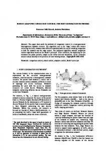
Figure 3: Tracking with occlusion
frames, which can reduce the error of detecting a false target. In the state 3 (S3): the target is lost by the vision detection algorithm. If the partial occlusion detection, based on Chi-square test, indicates that the target is still in the image and may be partially occlude, we manage to give the high weightings to the dynamic features and the color feature, which are less affected by the partial occlusion, while reduce the weightings to the geometric features. We keep this setting of the discriminant function for m frames to try to retrieve the target in the next m frames. Figure 3 shows an example of the tracking a toy car using the proposed the vision detection algorithm in the ground test. In Figure 3, the solid window is the measured location of the target, and the dash window is the predicted location of the target in the image plane. First the vision detection algorithm automatically initialize the detection, then lock the target. When the target is partially occluded, the vision algorithm give high weightings to the dynamic and color features in the discriminant function. Thus, the target still can be detected, even thought it is partially occluded.
Γ is the threshold valued which is decided experientially based on training data. Then this function of the classifier is to assign the target class to the object whose value of the discriminant function is the smallest, and also smaller than the specified threshold value. 2.2.3 Finite state machine The finite state machine plays a critical role in our project to dynamically chooses necessary features and give different weightings to each features in the discriminant function under different tracking conditions, shown in Figure 2. In the state 0 (S0): since there is no target found in the image, only pure static features are used in discriminant function (Equation 1) to identify the target in the entire image.
3 Tracking control After detecting the target in the image, the visual tracking control system is proposed to control the pan/tilt servo mechanism to minimize a tracking error function, which is also called eye-in-hand visual servoing. In our project, the tracking error function is defined in the visual sensor frame as: � e(t)
=
=
In the state 1 (S1): the same target has continously been found by the algorithm less than n frames. The discriminant function in (1) still uses static features in the pattern recognition, but enables a Kalman filtering to estimate the possible location of the target in the next frame. In the state 2 (S2): the same target has continously been found by the algorithm more than n frames. We then have confidence to decide that this target is the one we want and use both static and dynamic features in the discriminant function to identify and lock the target in the successive
�
� −
θc∗ φ∗c
�
⎞ x ¯ � ∗ � ) θc fc ⎟ ⎜ − ⎠ ⎝ y¯ φ∗c ) tan−1 ( � fc2 + x ¯ ⎛
Figure 2: Decision making using finite state machine
θc φc
tan−1 (
(3)
where [θc , φc ]T are the measured relative angles between the physical center of the visual sensor and the target illustrated in Figure 4, and [θc∗ , φ∗c ]T are the desired relative angles. The purpose of the design of the tracking control law is to minimize the error function given in (3) by choosing a suitable control input u(k). We employ a PI controller
400
0.1
0.05
0
tracking error (rad)
−0.05
−0.1 The tracking error in vertical direction The tracking error in horizontal direction −0.15
−0.2
−0.25
−0.3
Detected frames 191 209 538 295 508 311 91 1162 529
4
6
8 Time (s)
10
12
14
16
consider the ego-motion compensation of the UAV in the further visual tracking algorithm.
Table 1: Experimental results Total frame 219 284 703 375 676 431 108 1544 646
2
Figure 5: The tracking error of θc and φc .
Figure 4: The relative angle between the UAV and target.
Times 1 2 3 4 5 6 7 8 9
0
Accuracy 87.21% 73.59% 76.53% 78.67% 75.15% 72.16% 84.26% 75.26% 81.89%
5 Conclusion In this paper, we present the design and implement of the visual tracking system to realize on-board tracking a ground moving target for a UAV, which combines the proposed vision-based target detection algorithm with tracking control strategy. The experiment results obtained from the real flight tests of the UAV show that the vision-based tracking system is to be able to automatically identify and track ground moving target, and the tracking error is bounded. To reduce the tracking error, more research effort will be given to integrate the ego-motion of the UAV with the visionbased tracking control system in the further research,.
given by u(k) = kp e(k) + ki Ts
k �
References e(i)
(4)
[1] N. Guenard, T. Hamel, and R. Mahony, “A practical visual servo control for an unmanned aerial vehicle,” IEEE Transactions on Robotics, vol. 24, pp. 331–340, 2008. [2] L. Mejias, S. Saripalli, P. Cervera, and G. S. Sukhatme, “Visual servoing of an autonomous helicopter in urban areas using feature tracking,” Journal of Field Robotics, vol. 23, pp. 185–199, 2006. [3] M. Meingast, C. Geyer, and S. Sastry, “Vision based terrain recovery for landing unmanned aerial vehicles,” in Proceedings of IEEE Conference on Decision and Control, Atlantis, Bahamas, 2004, pp. 1670–1675. [4] J. Kim and S. Sukkarieh, “Slam aided gps/ins navigation in gps denied and unknown environments,” in The 2004 International Symposium on GNSS/GPS, Sydney, Australia, 2004. [5] E. Trucco and K. Plakas, “Video tracking: A concise survey,” IEEE Transactions on Oceanic Engineering, vol. 31, pp. 520–529, 2006. [6] E. N. Johnson, A. J. Calise, Y. Watanabe, J. Ha, and J. C. Neidhoefer, “Real-time vision-based relative aircraft navigation,” Journal of Aerospace Computing, Information, and Communication, vol. 4, 2007. [7] Q. M. Zhou and J. K. Aggarwalb, “Object tracking in an outdoor environment using fusion of features and cameras,” Image and Vision Computing, vol. 24, pp. 1244–1255, 2006. [8] H. Veeraraghavan, P. Schrater, and N. Papanikolopoulos, “Robust target detection and tracking through integration of motion, color and geometry,” Computer Vision and Image Understanding, vol. 103, pp. 121–138, 2006. [9] A. R. Smith, “Color gamut transform pairs,” in Proceedings of the 5th annual conference on Computer graphics and interactive techniques, New York, USA, 1978, pp. 12–19. [10] M. J. Swain and D. H. Ballard, “Color indexing,” International Journal of Computer Vision, vol. 7, pp. 11–32, 1991.
i=1
We choose kp = 1 and ki = 0.75 for both of the pan/tilt servo controllers based on the model of the pan/tilt servo mechanism, and verify the controllers in simulation and ground tests.
4
Experiment results and discussion
The proposed vision-based tracking algorithm is implemented in the on-board system of the unmanned helicopter: SheLion. The processing rate of the algorithm is 16 fps. During the real flight tests, the helicopter is manually controlled to hover at a fixed position 10 meters above the flat ground, and the on-board visual tracking system automatically identify and track the ground moving target: a toy car, which is manually controlled to randomly move in the flat ground. We performed nine times of visual tracking tests and the tracking results are shown in table 1. During these tests, the visual tracking system can successfully identify and track the ground target. One example of the tracking errors in vertical and horizontal direction is shown in Figure 5, which indicates that the tracking error is bounded. The experimental results demonstrate the robustness and effectiveness of the visual tracking system, which can automatically identify and track the moving target in the real flight. The tracking errors, however, are greater than these in ground tests, since the ego-motion and vibration of the UAV platform may degrade the performance of the visual tracking system. That is the reason why we are going to
401