SUBMITTED TO IEEE TRANSACTIONS ON SERVICE COMPUTING
1
Runtime Monitoring of Web Service Conversations Jocelyn Simmonds, Yuan Gan, Marsha Chechik, Shiva Nejati, Bill O’Farrell, Elena Litani, and Julie Waterhouse
Abstract—For a system of distributed processes, correctness can be ensured by (statically) checking whether their composition satisfies properties of interest. However, web services are distributed processes that dynamically discover properties of other web services. Since the overall system may not be available statically and since each business process is supposed to be relatively simple, we propose to use runtime monitoring of conversations between partners as a means of checking behavioural correctness of the entire web service system. Specifically, we identify a subset of UML 2.0 Sequence Diagrams as a property specification language and show that it is sufficiently expressive for capturing safety and liveness properties. By transforming these diagrams to automata, we enable conformance checking of finite execution traces against the specification. We show how our language can be used to specify the Specification Property System (SPS) [1]. We describe an implementation of our approach as part of an industrial system. Finally, we discuss our experience of specifying and monitoring a number of properties from three existing applications. Index Terms—nondeterministic finite automata, runtime monitoring, sequence diagrams, temporal logic patterns, web service conversations
I. I NTRODUCTION Recent years have seen an emergence of the field of web services, which use Service-Oriented Architectures (SOA) to dynamically discover and bind to services in order to increase the flexibility of business interactions. Each service consists of components and can discover other components using published interfaces. An SOA component can be written in a traditional compiled language such as JavaTM , or in an XMLcentric language such as BPEL [2]. An SOA module is made up of multiple SOA components which are commonly referred to as web services. Since each web service is a relatively simple process, analysis can concentrate on the message exchange between partners – their conversations. For a classical system of distributed processes, correctness can be ensured by statically checking their composition against properties of interest. The same approach has been taken by several researchers in the context of web services as well, e.g., [3]–[7]. While static analysis is very appealing – errors are discovered ahead of time and without the need to exercise the system, this approach has several major limitations: • Web services typically communicate via infinite-length channels, so the problem is decidable only under certain conditions [8]. J. Simmonds and M. Chechik are with the Department of Computer Science, University of Toronto, Toronto, ON, M5S 3G4, Canada e-mail: {jsimmond,chechik}@cs.toronto.edu. S. Nejati is with the Simula Research Laboratory, P.O.Box 134, 1325 Lysaker, Norway email:
[email protected]. Y. Gan, B. O’Farrell, E. Litani and J. Waterhouse are with the IBM Toronto Lab, 8200 Warden Ave, Markham, ON, L6G 1C7, Canada email: {ygan,billo,elitani,juliew}@ca.ibm.com. c Copyright 2008, International Business Machines. All Rights Reserved.
•
•
•
Web applications usually interact with web services developed by partners. Partners are only required to make web service interfaces public, not the code. Realistic web services exchange many types of messages: some synchronous, some asynchronous, and some with acknowledgements and priorities. Web services are typically heterogeneous, i.e., each component can be implemented in a different programming language.
Instead, we concentrate on the dynamic analysis via runtime monitoring, which tries to ensure the quality of an application through the analysis of runtime events. These events can be analyzed online – during the execution of the application, or offline – after execution has terminated. The latter can be used to express free-form queries over all generated events. However, since these queries are not necessarily known a priori, the runtime data collected might not be sufficient to answer the relevant questions, or, on the other extreme, the amount of data collected may become excessive and hard to manage, leading to intractable analysis. Online techniques, on the other hand, monitor predefined properties, collecting just those events which are related to these properties. While expressing properties beforehand may be non-trivial, the collected data is guaranteed to be both small and sufficient to check these properties; they also serve as an additional, and very valuable, documentation of the desired behaviour of the system. Monitoring as the system runs also provides a chance of recovery once a problem has been detected, e.g., by terminating execution or trying to return to a stable state. For these reasons, we use online monitoring techniques in this paper. Our goal is thus to create an industrial-strength (in partnership between the University of Toronto and the IBM Toronto Lab) online monitoring framework that is non-intrusive, supports the dynamic discovery of web services, deals with synchronous and asynchronous communication and partners implemented in different languages, allows for specifying and efficient monitoring of a variety of temporal behaviour, permits recovery strategies (this is not part of the current paper), and is usable by practitioners. We also aim to create an industrial-strength language for specifying temporal behaviour that captures the distributed, interactive, and message-driven nature of business processes. Our language should enable specifying a variety of properties and be amenable to efficient runtime monitoring, allowing the analysis of orchestrations involving multiple partners, from the point of view of the orchestrating service. We believe that such a language should have the following characteristics: 1) its notation should be visual; 2) it should allow the specification of desired temporal behavior, via sequences of events;
SUBMITTED TO IEEE TRANSACTIONS ON SERVICE COMPUTING
3) it should have an explicit emphasis on components and enable dealing with different types of message exchange; and 4) it should be able to specify positive and negative scenarios of interaction as well as global properties. These characteristics are necessary for the resulting language to be usable by practitioners. Having considered a few behavioral graphical languages, such as GIL [9], Time Line Editor [10], Message Sequence Charts (MSCs) [11] and Live Sequence Charts (LSCs) [12], we have chosen UML 2.0 Sequence Diagrams (SDs) [13] as the basis for our specification language. SDs, used to capture interactions in the form of message passing between objects, have been widely adopted by industry as a suitable language for describing and documenting scenario-based requirements specifications, with additional constraints expressed using the Object Constraint Language (OCL) [?]. The other UML 2.0 diagrams did not meet our requirements for a specification language: no support for multiple parties (state machines); only allow the specification of simple sequences of events (communication and interaction overview diagrams); too lowlevel (activity diagrams); cannot be used to specify behavior (class diagrams). SDs are a feature-rich language without a formal semantics. In this paper, we identify a subset of SDs that is sufficiently expressive for capturing safety and liveness properties. While liveness properties are not monitorable in general, they can be effectively checked for web services with finitely terminating behaviours. Specifically, we aim to generate three types of monitors: accepting individual (existential) negative behaviours which correspond to a violation of safety properties; their dual, accepting universal positive behavior which corresponds to finite liveness (once an event occurs, the rest of the events must occur before termination); as well as individual positive behaviours which can be easily specified in SDs. For this latter type, we do not look for violations (if a given trace does not correspond to a desired behaviour, perhaps others will), but do report when we were able to observe their satisfaction. To enable monitoring, we formalize our subset of SDs using finite-state automata. Similar approaches to formalizing sequence diagram variants have been previously proposed by other researchers, e.g., [14]–[16]. Since automata and logic are intimately related, an automata-based characterization allows us to investigate connections between SDs and temporal logics, and translate SDs to automata to enable conformance checking of finite execution traces against their specifications expressed in SDs. We then show that this language is sufficiently expressive to capture a wide variety of frequently used properties, captured and catalogued in the Specification Pattern System (SPS) [1]. This approach also gives basis for tool support to enable usable specification of runtime conversations. A. A Motivating Example Consider, for example, a web-based Loan Application sysR tem (LA), distributed as a sample application with the IBM R
WebSphere Integration Developer v6.0.2. Users enter loan application information (name, taxpayer id, loan amount)
2
(a)
(b)
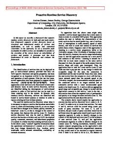
Fig. 1: The LA system: (a) workflow describing the high-level steps of the LA system; (b) an assembly diagram describing how the main process of the LA system interacts with its partners. through a web page, and are eventually informed of the status of their applications. The LA workflow first checks if the user’s credit score is valid, and will decline their loan request if the user has a bad credit score, i.e., less than 750. A credit score is considered valid if it is between 300 and 850. If the credit score is good, the workflow then checks the loan amount: loans for $50,000 or less are automatically approved; loans for larger amounts are earmarked for manual approval. The workflow diagram in Fig. 1(a), which is described as a BPEL specification, shows high level steps that are executed in a loan application system, and Fig. 1(b) shows an assembly diagram describing how the main process of the LA system invokes its partners, such as CreditCheck (implemented in Java), rule groups (LoanLimit), or human tasks (FollowUpDeclinedApp, CompleteTheLoan and ProcessTheApplication). Specifically, the CheckCredit activity in Fig. 1(a) invokes the CreditCheck partner in Fig. 1(b), and the conditional activities ScoreEvaluation and AutoApprovalTest invoke the LoanLimit partner. The
SUBMITTED TO IEEE TRANSACTIONS ON SERVICE COMPUTING
P1 P2 P3 P4 P5
3
The credit score should always be valid, i.e., between 300 and 850. The credit score should eventually be checked if the loan amount is greater than zero. A loan cannot be granted if the loan amount is less than or equal to zero. After checking that the applicant has a good credit score, a loan cannot be granted if the loan amount is less than or equal to zero. No-one can get a loan without first going through a credit check.
TABLE I: Several properties of the LA system. partners in Fig. 1(b) implement the following functions: CreditCheck uses the taxpayer id to retrieve the corresponding credit score; the LoanLimit rule group checks the credit score and the loan amount. The human tasks CompleteTheLoan, ProcessApplication and FollowUp follow the application results Approved, ManualApproval and Declined, respectively. Since the LA system is a composition of several distributed business processes, its correctness depends on the correctness of its partners and their interactions. For example, the system should guarantee that every request is eventually acknowledged and none are lost or blocked indefinitely, or that loans are only given to customers with a good credit score. However, in the provided LA application, the CreditCheck module assigns a credit score at random, without using the customer id, thus preventing the overall system from satisfying this property. Table I shows some properties of the LA system that can be expressed using our SD subset. For example, P1 and P2 are possible safety and liveness properties, respectively.
arrows denoting messages that are sent from one object to another, synchronously (solid arrowhead) or asynchronously (open arrowhead). We refer to Sequence Diagrams with these features as basic. Basic Sequence Diagrams can be augmented by a number of operators to capture more sophisticated scenarios. We use the operators described below in our property specification language, and refer to our language as SD. •
•
• •
B. Organization of the Paper The rest of this paper is organized as follows. We describe syntax of the subset of UML 2.0 sequence diagrams used for expressing properties of web service conversations in Section II. We describe the semantics of our chosen subset of SDs and show how to translate it into automata for runtime monitoring in Section III. We then show how our specification language can be used to specify the complete set of temporal logic property patterns in Section IV. We describe the implementation of the runtime monitoring framework in Section V and report on the experience using this framework for three existing web service systems in Section VI. After comparing our approach with related work in Section VII, we conclude the paper in Section VIII with a summary and an outline of the future research directions. II. A L ANGUAGE
FOR
S PECIFYING C ONVERSATIONS
We choose a subset of UML 2.0 Sequence Diagrams as the language for specifying web service conversations. This subset satisfies the requirements set forth in the previous section. We formalize this subset in Section III and discuss its expressive power in Section IV. Sequence Diagrams is a popular formalism for modeling behavioural scenarios by describing sequences of messages communicated between different objects over time. An example Sequence Diagram describing a scenario of the LA system is shown in Fig. 2(a). Sequence Diagrams have two dimensions: vertical, representing time, and horizontal, representing objects. Each object is illustrated by a rectangle with a vertical dashed line, called a lifeline. Lifelines are connected by horizontal
•
Compositional operators: Operators parallel (par) and alternatives (alt) are used to compute intersection and union of two SDs, respectively. The operator loop is used for repeating the scenario described by an SD multiple times, and opt – for denoting an optional scenario, equivalent to alt with only one argument. Alphabet changing operators: Operators consider and ignore are used for modifying the communicating alphabet of SDs. Critical operator: The critical operator is used to ensure atomicity of the enclosed sequence. Assertion and negation operators: Operators assert and negate allow users to express mandatory and forbidden system scenarios, respectively. Interaction use operator: SDs can be shared by reference, using the ref operator. This is a shorthand for copying the contents of the referred SD where the ref operator occurs, and is a new feature in UML 2.0.
To describe system scenarios, we often need to express complementation of an individual message or a set of messages appearing on the same arrow. The negate operator is unsuitable for complementing sets because it captures negative sequences of messages rather than set complementation. Instead, we use the message complementation operator, originally introduced in the Property Sequence Charts (PSC) language [17]. We denote the complement of a message m by ¬m and define it as the set of all messages that are potentially exchanged between objects of the system except for m. An example sequence diagram describing a scenario of the LA system is shown in Fig. 2(a). The diagram contains three objects, MnPs, CtCk, and LnLt. Object MnPs corresponds to the main workflow of the LA system, and CtCk and LnLt correspond to components CheckCredit and LoanLimit, respectively. The diagram in Fig. 2(a) shows two alternative scenarios: In the first, MnPs sends a check credit score request, i.e., ckCtSe, to CtCk, and then a check loan amount request, i.e., ckLnAt, to LnLt. In the second, LnLt receives a check loan amount request from MnPs. Since the credit score has not yet been checked, LnLt sends a check credit score request to CtCk. Basic Sequence Diagrams, denoted BasicSDs, are the building blocks of our language. The critical, alphabet changing, interaction use, assert, and compositional operators, except for par, can be intermixed and applied any number of times to
SUBMITTED TO IEEE TRANSACTIONS ON SERVICE COMPUTING
4
SD Basic consider {ckLnAt,ckCtSe,ckTrID} MnPs
alt
CtCk
LnLt q2
?ckCtSe
ckCtSe ckLnAt
q0
!ckCtSe
q1
!ckLnAt
q3
!ckLnAt q4
?ckCtSe
?ckLnAt
q6
ckLnAt ckCtSe
?ckLnAt
(a)
?ckCtSe
q5
(b) Σsys \ Σ q4
!ckLnAt
?ckLnAt
Σsys \ Σ q2
?ckCtSe ?ckCtSe
q2
Σsys \ Σ !ckLnAt
?ckCtSe q1
!ckLnAt
!ckCtSe
q3
?ckCtSe
?ckLnAt
q0
?ckLnAt
q4
!ckLnAt
?ckCtSe
q5
q0 Σsys
q12
?ckLnAt
q3 !ckLnAt
q12
Σsys \ Σ
ǫ
!ckLnAt Σ
ǫ q8
?ckLnAt
q9
!ckCtSe
?ckCtSe
q10
Σ
ǫ
Σsys \ Σ
q6 ǫ
?ckCtSe
q5
!ckCtSe q1
Σsys \ Σ
q6
q8
?ckLnAt
q9
q11 Σsys \ Σ
!ckCtSe
Σsys \ Σ
(c)
q10
?ckCtSe
Σsys \ Σ
Σsys
q11
Σsys \ Σ
(d)
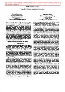
Fig. 2: (a) An SD describing a scenario of the LA example; (b) the NFA corresponding to the first argument of the alt operator in Fig. 2(a); (c) the NFA corresponding to the complete scenario in Fig. 2(a); and (d) the resulting runtime monitor.
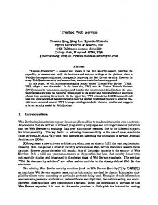
BasicSDs. The use of negate and par operators, however, is restricted to sequence diagrams which do not use an assert operator. We discuss this assumption and the rationale behind it in Section III-F2 and show in Section IV that even with this restriction, the resulting language remains very expressive. The grammar for our language, SD, is given in Fig. 3 where BasicSD , par , alt , loop, critical , opt , negate, assert , consider , ignore and ref are terminal symbols, and E is a set of SD messages. Since operators consider and ignore change the communicating alphabet of SDs, they take a set E of messages as an input argument. In what follows, we denote by SD the set of Sequence Diagrams generated by the grammar in Fig. 3. III. F ORMALIZING S EQUENCE D IAGRAMS In this section, we provide a formal description of semantics of Basic SDs as well as the operators described in Section II by adopting the automata-theoretic approach of Alur and Yannakakis [14]. A. Nondeterministic Finite Automata Let Σ be an alphabet. We define a trace σ over Σ to be a finite sequence σ0 σ1 . . . σn , where ∀i · 0 ≤ i ≤ n, σi ∈ Σ. We denote by Σ∗ the set of all finite traces over Σ. Definition 1 (Projection “↓”): Let Σ′ ⊆ Σ be an alphabet, and σ = σ0 . . . σn be a trace over Σ. The projection of σ to Σ′ , denoted σ ↓Σ′ , is obtained by replacing every σi (0 ≤ i ≤ n) by the silent symbol ǫ iff σi ∈ / Σ′ . Definition 2 (NFA [18]): A Non-deterministic Finite Automaton (NFA) A is a tuple (Σ, Q, δ, Q0 , F ), where Σ is a set
of input alphabet, Q is a finite set of states, δ ⊆ Q × Σ × Q is a transition relation, Q0 ⊆ Q is a set of initial states, and F ⊆ Q is a set of accepting states. A trace σ = σ0 σ1 ...σn is accepted by A iff there is a sequence q0 q1 ...qn+1 of states s.t. q0 ∈ Q0 , qn+1 ∈ F , and for every 0 ≤ i ≤ n, (qi , σi , qi+1 ) ∈ δ. The language of A, L(A), is the set of all traces accepted by A. An example NFA over the alphabet {!ckCtSe, ?ckCtSe, !ckLnAt, ?ckLnAt} is shown in Fig. 2(b). In cases where states do not have outgoing transitions for some symbols in Σ, e.g., state q1 on ?ckLnAt in Fig. 2(b), it is assumed that this symbol causes a transition to a (nonaccepting) dead-end state, which is usually not shown. Let (q, a, q ′ ) be a transition in an NFA A. We often refer to a as the label of the transition from q to q ′ . For an NFA A with ǫ transitions, let L(A) to be the set of traces of A with the occurrences of ǫ removed. States in NFAs may have several outgoing transitions on the same input symbol, or may have transitions labeled ǫ, indicating a silent move. Deterministic finite automata (DFAs) are NFAs where each state has at most one outgoing transition on each non-silent symbol. Every NFA can be converted into a DFA using the subset construction algorithm [18]. B. Basic SDs We define Basic SDs as follows. Definition 3 (Basic SDs [14]): A Basic SD S is a tuple (I, E, f , O), where •
I is a finite set of objects.
SUBMITTED TO IEEE TRANSACTIONS ON SERVICE COMPUTING
5
SD ::= BasicSD | unaryOp SD | SD alt SD | NotAssertedSD par NotAssertedSD | assert SD | negate NotAssertedSD NotAssertedSD ::= BasicSD | unaryOp NotAssertedSD | NotAssertedSD alt NotAssertedSD | negate NotAssertedSD | NotAssertedSD par NotAssertedSD unaryOp ::= consider E | ignore E | loop | critical | opt | ref Fig. 3: Grammar of the SD language. E is a finite set of event occurrences that is partitioned into send events, denoted by !E, and receive events, denoted by ?E. The set of events sent and received by an object i ∈ I is denoted by Ei . • f : !E → ?E is a bijective mapping that associates each send event e with a unique receive event f (e), and each receive event e′ with a unique send event f −1 (e′ ). • O is a set of total order relations