A trie is a binary-tree-like data structure for LPM. Each prefix is represented by a node in the trie, and the value of the prefix corresponds to the path from the root ...
SCALABLE HIGH-THROUGHPUT SRAM-BASED ARCHITECTURE FOR IP-LOOKUP USING FPGA Hoang Le, Weirong Jiang, Viktor K. Prasanna Ming Hsieh Department of Electrical Engineering University of Southern California Los Angeles, CA 90089, USA {hoangle, weirongj, prasanna}@usc.edu ABSTRACT Most high-speed Internet Protocol (IP) lookup implementations use tree traversal and pipelining. However, this approach results in inefficient memory utilization. Due to available on-chip memory and pin limitations of FPGAs, stateof-the-art designs on FPGAs cannot support large routing tables arising in backbone routers. Therefore, ternary content addressable memory (TCAM) is widely used. We propose a novel SRAM-based linear pipeline architecture, named DuPI. Using a single Virtex-4, DuPI can support a routing table of up to 228K prefixes, which is 3× the state-of-the-art. Our architecture can also be easily partitioned, so as to use external SRAM to handle even larger routing tables (up to 2 M prefixes), while maintaining a 324 MLPS throughput. The use of SRAM (instead of TCAM) leads to orders of magnitude of reduction in power dissipation. Employing caching to exploit Internet traffic locality, we can achieve a throughput of 1.3 GLPS (billion lookups per second). Our design also maintains packet input order, and supports in-place nonblocking route updates. 1. INTRODUCTION Most hardware-based solutions for high speed packet forwarding in routers fall into two main categories: ternary content addressable memory (TCAM)-based and dynamicstatic random access memory (DRAM/SRAM)-based solutions. Although TCAM-based engines can retrieve results in just one clock cycle, their throughput is limited by the relatively low speed of TCAMs. They are expensive and offer little adaptability to new addressing and routing protocols [1]. As shown in Table 1, SRAMs outperform TCAMs with respect to speed, density, and power consumption. Since SRAM-based solutions utilize some kind of tree traversal, they require multiple cycles to perform a single IP lookup. Several researchers have explored pipelining to improve the throughput. A simple pipelining approach is to map each SUPPORTED BY THE UNITED STATES NATIONAL SCIENCE FOUNDATION UNDER GRANT NO. CCF-0702784. EQUIPMENT GRANT FROM XILINX INC. IS GRATEFULLY ACKNOWLEDGED.
Table 1. Comparison of TCAM and SRAM technologies Maximum clock rate (MHz) Cell size (# transistors/bit) [5] Power consumption (Watts)
TCAM (18 Mb chip) 266 [2] 16 12 ∼ 15 [6]
SRAM (18 Mb chip) 400 [3, 4] 6 ≈ 0.1 [7]
tree level onto a pipeline stage with its own memory and processing logic. One packet can be processed every clock cycle. However, these designs result in inefficient memory utilization, since each node must store the addresses of its child nodes. This inefficiency dictates the size of the routing table that an SRAM-based solution can support. In addition, since each stage needs its own memory, it is not feasible to use external SRAM for all stages, due to the constraint on the number of I/O pins. We have two constraints: the number of external SRAM banks and the limited amount of onchip memory. These two constraints are interdependent and make the current solutions very difficult to scale to support larger routing tables. This scalability has been a dominant issue for any implementation on FPGAs. The key issues in designing an architecture for IP lookup are (1) the size of supported routing table, (2) high throughput, (3) in-order packet output, (4) incremental update, and (5) power consumption. To address these challenges, we propose and implement a scalable, high-throughput SRAMbased dual linear pipeline architecture for IP Lookup on FPGAs (DuPI). This paper makes the following contributions: • To the best of our knowledge, this architecture is the first binary-tree-based design to use on-chip FPGA resources only to support a large routing table up to 228K prefixes. This is 3 times the size of a Mae-West routing table (rrc08, 20060101, 83662 prefixes) [8]. • DuPI is also the first architecture that can easily interface with external SRAM. Using this we can handle up to 2M prefixes, which is 8 times the size of the current largest routing table (rrc11, 20080305, 246583 prefixes) [8].
• The implementation results show a sustained throughput of 324 MLPS, whether or not off-chip commodity SRAM is used, for a non-cache design, and 1.3 GLPS for cache-based design. This is a promising solution for next generation IP routers. The rest of the paper is organized as follows. Section 2 covers the background and related work. Section 3 introduces the DiPI architecture. Section 4 describes DuPI implementation. Section 5 presents implementation results. Section 6 concludes the paper. 2. BACKGROUND AND RELATED WORK 2.1. Trie-based IP Lookup The IP lookup problem is longest prefix matching (LPM) problem. The common data structure in algorithmic solutions for performing LPM is some form of tree, such as trie [9]. A trie is a binary-tree-like data structure for LPM. Each prefix is represented by a node in the trie, and the value of the prefix corresponds to the path from the root of the tree to the node. The prefix bits are scanned left to right. If the scanned bit is 0, the node has a child to the left. A bit of 1 indicates a child to the right. IP lookup is performed by traversing the trie according to the bits in the IP address. When a leaf is reached, the last seen prefix along the path to the leaf is the longest matching prefix for the IP address. The time to look up a uni-bit trie (which is traversed in a bit-by-bit fashion), is equal to the prefix length. The use of multiple bits in one scan increases the search speed. Such a trie is called a multi-bit trie. 2.2. Related Work Since the proposed work addresses FPGA implementation, we summarize related work in this area. TCAM is widely used to simplify the complexity of the designs. However, TCAM results in lower overall clock speed and increases the power consumption of the entire system. Song et al. [10] introduce an architecture called BV-TCAM, which combines the TCAM and the Bit Vector (BV) algorithm to compress effectively the data representations and boost the throughput. Due to the relatively low clock rate of TCAMs, this design can only handle a lookup rate of about 30 MLPS. The fastest IP lookup implementation on FPGAs to date is reported in [11], which can achieve a lookup rate of 325 MLPS. This is a bidirectional optimized linear pipeline architecture, named BiOLP, which takes advantage of the dualported SRAM to map the prefix trie in both directions. By doing this, BiOLP achieves a perfectly balanced memory allocation over all pipeline stages. BiOLP also supports a Mae-West routing table (rrc08, 84K prefixes). Another very fast IP lookup implementation on FPGAs to date is described in [12], which can achieve a lookup rate of 263 MLPS. Their architecture takes advantage of both a traditional hashing scheme and reconfigurable hardware.
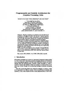
They implement only the colliding prefixes (prefixes that have the same hashing value), on reconfigurable hardware, and the remaining prefixes in a main table in memory. This architecture supports a Mae-West routing table (rrc08, 84K prefixes), and can be updated using partial reconfiguration when adding or removing prefixes. However, it does not support incremental update, and the update time is lower bounded by the time required for partial reconfiguration. It is also not clear how to scale this design to support larger routing tables, due to the nondeterministic characteristic of the hashing function. Moreover, the power consumption of this design is potentially high, due to the large number of logic resources utilized. Baboescu et al. [17] propose a Ring pipeline architecture for tree-based search engines. The pipeline stages are configured in a circular, multi-point access pipeline so that the search can be initiated at any stage. This architecture is implemented in [18] and achieves a throughput of 125 MLPS. Sangireddy et al. [13] propose two algorithms, ElevatorStairs and log W-Elevators, which are scalable and memory efficient. However, their designs can only achieve up to 21.41 MLPS. Meribout et al. [14] present another architecture, with the lookup speed of 66 MLPS. In this design, a commodity Random Access Memory (RAM) is needed, and the achieved lookup rate is reasonably low. 3. DuPI ARCHITECTURE 3.1. Binary-tree-based IP Lookup We propose a memory efficient data structure based on a binary tree. Binary search tree (BST) is a special binary tree data structure with the following properties: (1) each node has a value; (2) the left subtree of a node contains only values less than the node’s value; (3) the right subtree of a node contains only values greater than the node’s value. In an optimal binary search tree, an element can be found in at most (1 + log2 N ) operations, where N is the number of nodes. Figure 1 illustrates a sample prefix set and its corresponding binary search tree. For simplicity, IP addresses with length of 8 bits are considered. Prefixes are padded with ones as shown in the third column. The fourth column is the number of padded bits. The padded prefix and its number of padded bits are concatenated, and this value is used to build the tree. However, the value that is stored in each node is the concatenation of the padded prefix and the length of the original prefix. For example, node #4 has the value of 01001111|101, not 01001111|011. All the prefixes are sorted in descending order, as shown in the last column. The header of an incoming packet is extracted and enters the tree from its root. At each node, only the k most significant bits of the node’s padded prefix and the packet’s IP address are compared, where k is the length of the node’s prefix. Given such a binary search tree, IP lookup is performed by traversing left or right depending on the comparison re-
Prefix P1 P2 P3 P4 P5 P6 P7 P8
0* 000* 010* 01001* 01011* 011* 110* 111*
‘1’ padded prefix 01111111 00011111 01011111 01001111 01011111 01111111 11011111 11111111
# padded bits 111 101 101 011 011 101 101 101
Sorted rank 3 8 5 7 6 4 2 1
Len+FID
Address Pipeline 1
(a) Prefix set
Len+FID LFIn LFOut
IP
Pipeline 2 Address
B Addr1
Data1
A
Comp
B
IP
B>A
Address
B>A
Address
Dual Port SRAM Addr2
Data2
IP
A
Comp
B
B
IP
LFIn LFOut Len+FID
Len+FID
Fig. 2. Block diagram of DuPI architecture
(b) Binary search tree
Fig. 1. Sample prefix set and its binary search tree sult at each node. If the packet header IP is smaller or equal to node’s value, it is forwarded to the left branch, and to the right branch otherwise. For example, assume that a packet with header’s IP of 01001010 arrives. At the root, the prefix 011∗, with length of 3, is compared with 010 of the header IP, which is smaller. Thus packet traverses to the left. The comparison with value in node #6 yields a smaller outcome, hence packet again traverses to the left. At node #7, the packet header matches the node’s prefix, and is forwarded to the left to find a longer prefix, if any. However, no match has been found at node #8, and hence, the prefix at node #7 (or P4) is the longest matched prefix. We must ensure that the proposed algorithm actually finds the longest matching prefix. Given two prefixes, PA and PB , PA is a longer matching prefix than PB iff PB is included in PA . This is referred to as PA is longer than PB hereafter. Property: Given two prefixes, PA and PB , if PA is longer than PB then PA belongs to the left branch of PB . Let PA� , PB� be PA , PB after 1-padding, respectively. Since PA is longer than PB , and prefixes are 1-padded, all bits of PA� and PB� are identical in all cases, except for the bits that make PA longer than PB . If these bits are all 1, we have PA� = PB� , else PA� < PB� . The use of the number of padded bits helps break the tie. As PA is longer than PB , the number of non-prefix bits of PA is smaller than that of PB , causing PA� < PB� . By property #2 of BST, PA belongs to the left branch of PB . Therefore, in all cases, the above property is satisfied. 3.2. DuPI Architecture A binary tree structure is utilized in our design. To ensure that every IP lookup results in the same number of operations or cycles, the IP address continues with all the comparisons even though a match may have already been found. A pipelining technique is used to increase the throughput. The number of pipeline stages is determined by the maxi-
mum number of operations needed to traverse the tree. For the design to work, each stage has its own memory (or table). Each table is one level of a binary tree structure, so the memory size doubles in each stage. For example, the first stage has only one element, the second one has two, the third one has four, and so on. The maximum number of elements in each stage is determined by 2n , where n is the stage number. The block diagram of the basic architecture and a single stage are shown in Figure 2. The architecture is configured as dual linear pipelines. At each stage, the memory has dual Read/Write ports so that two packets can be input every clock cycle. The content of each entry in the memory includes (1) the padded prefix of the current node; (2) the length of the prefix; and (3) the status of this prefix (up/down). At each stage, there are 4 data that are forwarded from the previous stage: the IP address of the package, the address to access the memory, the length, and flow information of the previously longest matched prefix. The memory address is used to retrieve the node’s value, which is compared with the packet’s IP address to determine matching status. If there is a match, and it is longer than the previously stored match, the length and flow information of the new match replace the old ones. The IP address is forwarded left or right depending on the comparison result, as described in Section 3.1. The comparison result (1 if packet’s IP is greater than node’s padded prefix, 0 otherwise) is concatenated with the current memory address and forwarded to the next stage. 3.3. Tree Mapping Algorithm A complete BST is required for efficient memory utilization. All levels must be fully occupied, except for the last one. In the last level, if it is not full, all elements must be as far left as possible. Given a sorted array of elements in ascending order, this BST can easily be built by picking the right pivot as the root and recursively building the left and right subtrees. Two cases of complete BSTs are illustrated in Figure 3. Let N be the number of elements, n be the number of
Write Bubble ID
0 1 Write Bubble Table
n-2 n-1
Addr
(a)
New Content
WE
Dual-Port SRAM
(b)
Fig. 3. Two cases of complete BST O1
I1 I2 I3
Miss
Cache Module
5-4 FIFO
4-1 FIFO
I4
O5
DuPBI
I5
I7
O3 O4
I6
O6
Miss
Cache Module
5-4 FIFO
4-1 FIFO
O7 O8
I8
Hit Hit
Fig. 5. Route update using write-bubbles
O2
DELAY
Fig. 4. Top level block diagram of cache-based DuPI levels, and Δ be the number of elements in the last level. The total number of nodes in all stages, excluding the last one, is 2n−1 − 1. Therefore, the number of nodes in the last stage is Δ = N − (2n−1 − 1). There are 2n−1 nodes in the last stage if it is full. If Δ ≤ 2n−1 /2, we have a complete BST, as in Figure 3 (a), or (b) otherwise. Let x be the index of the desired root. x can be calculated as: x = 2n−2 −1+Δ for case (a), or x = 2n−1 −1 for case (b). The complete BST can be built recursively, as described in Algorithm 1. Algorithm 1 C OMPLETE BST(S ORTED A RRAY ) Input: Array of N elements is sorted in ascending order Output: Complete BST 1: n = �log2 (N + 1)�, Δ = N − (2n−1 − 1) 2: if (Δ ≤ 2n−1 /2) then 3: x = 2n−2 − 1 + Δ 4: else 5: x = 2n−1 − 1 6: end if 7: Pick element x as root 8: Left-branch of x = C OMPLETE BST(left-of-x sub-array) 9: Right-branch of x = C OMPLETE BST(right-of-x sub-array)
3.4. Cache-based DuPI The proposed architecture can be utilized as an engine in a cached-based DuPI architecture, as shown in Figure 4. Our experiments (Section 5.1) show that 4 inputs per pipeline is the optimal number. Therefore, the cache-based architecture consists of seven modules: cache (×2), 4-1 FIFO (×2), DuPI, Delay, and 5-4 FIFO module (×2). Notation m − n FIFO denotes a FIFO with m inputs and n outputs. At the front are the two cache modules, which take in up to 8 IP addresses at a time. These modules take advantage of the internet traffic locality due to the TCP mechanism and application characteristics [15]. The most recently searched packets are cached. Any arriving packet accesses the cache
first. If a cache hit occurs, the packet will skip traversing the pipeline. Otherwise, the packet must traverse the pipeline. For IP lookup, only the destination IP of the packet is used to index the cache. The cache update will be triggered, either when there is a route update that is related to some cached entry, or after a packet that previously had a cache miss retrieves its search result from the pipeline. Any replacement algorithm can be used to update the cache. The Least Recently Used (LRU) algorithm is used in the implementation. We can insert multiple packets per clock cycle as long as there are enough copies of the cache for those packets to access simultaneously. We can insert at most four packets during one clock cycle per pipeline. Without caching, the packet input order is maintained due to the linear architecture. However, with caching, the packet which has a cache hit will skip traversing the pipeline, and may go out of order. We add buffers to delay outputting the packets with a cache hit, as shown in Figure 4 (Delay module). The length of the delay buffer is equal to the sum of the pipeline depth and the queue length. By these means, the packet input order can be preserved. Packets coming out of the Delay module, as well as each pipeline are buffered in 5-4 output FIFOs. 3.5. Route Update We define two types of updates: in-place update and newroute update. Once the FPGA is configured and a routing table is stored, all updates on these prefixes are defined as in-place updates. These updates include change flow information and “bring up or down a prefix”. We can perform inplace update by inserting write bubbles [16] (Figure 5). The new content of the memory is computed off-line. When an in-place update is initiated, a write bubble is inserted into the pipeline. Each write bubble is assigned an ID. There is one write bubble table (WBT) in each stage. It stores the update information associated with the write bubble ID. When it arrives at the stage prior to the stage to be updated, the write bubble uses its ID to look up the WBT. Then it retrieves (1) the memory address to be updated in the next stage, (2) the new content for that memory location, and (3) a write enable bit. If the write enable bit is set, the write bubble will use the new content to update the memory location in the next stage. For new-route update, if the structure of the tree is changed, the BST must be rebuilt, and the entire memory content of each pipeline stage must be reloaded.
4. DuPI IMPLEMENTATION 4.1. Cache and FIFO Modules As mentioned above, full associativity and LRU are used to implement the cache module. Our experiments show that 16-entry cache is sufficient for our purposes. Since this is a tree-based architecture, all the prefixes are stored in block RAM (BRAM). It is desirable that a large amount of BRAM is used to store routing tables. Therefore, this module is implemented using only registers and logic. There are two types of FIFOs in the architecture, as shown in Figure 4. Even though they have different numbers of input and output ports, their functionalities are identical. Since the number of inputs is different from the number of outputs in each FIFO, and there is only one clock for both the writing and reading sides, these are synchronous FIFOs with conversion. For simplicity, no handshaking feature is implemented, and therefore any further arriving packet is dropped when the FIFO is full. Similar to the cache implementation, the two FIFOs are implemented using only registers and logic, to save BRAM for routing tables. Details of the implementations are not described in this paper due to page limitations. 4.2. DuPI As mentioned earlier, the memory size in each stage doubles that of the previous stage. Therefore, if they are full, stage 0 has one entry, stage 1 has two entries,· · · , stage n has 2n entries. Each entry includes (1) a padded prefix (32 bits), (2) a prefix length (5 bits), (3) flow information (4 bits), and (4) an active status (1 bit). That makes a total of 42 bits per entry. On a Xilinx FPGA, BRAM comes in blocks of 18Kb, which can hold up to 438 entries. Hence, stages from 0 to 8 need one block of BRAM for each stage, or 9 blocks total. We can avoid these inefficient BRAM by using distributed RAM, due to the unit block of only 16 bit. However, this optimization adds only 4K prefixes to the total, which is not significant. Our target chip, Virtex-4 FX140, has 9936Kb of BRAM on chip, or 552 blocks. With this amount of memory, we can have 17 full stages, which hold 128K prefixes, and one half-full stage, which holds 100K entries, for a total of 228K prefixes. The distributions of prefixes and BRAMs are shown in Table 2 for stages 9 to 17. Our mapping algorithm ensures that all entries of the last stage are left-aligned, and thus can be safely mapped onto 228 memory blocks without getting “out-of-bound” memory access violations. Our design utilizes 539 memory blocks (311 for first 17 stages, 228 for the last stage), or about 97.6% of available memory. Let S be the size of a routing table, and assume that 128K < S < 228K. The number of memory blocks needed can be calculated: 311 + 42 ∗ (S − 128K)/18 Kb. In our design, external SRAM can be used to handle larger routing tables. Since only the last stage is allowed not to be full, we use 311 blocks (or 56%) of on-chip BRAM for the first 17 full stages, and move the subsequent stages
Table 2. Number of prefixes and BRAMs in stages 9 to 17 Stage # # prefixes # BRAMs
9 512 2
10 1K 3
11 2K 5
12 4K 10
13 8K 19
14 16K 38
15 32K 75
16 64K 150
17 100K 228
Table 3. Number of prefixes and amount of SRAM SRAM (Mb) # external stages # prefixes
6 1 256K
18 2 512K
42 3 1M
90 4 2M
onto external SRAM. In the current market, SRAM comes in 2 Mb to 32 Mb packages [4], with data widths of 18, 32, or 36 bits, and a minimum access frequency of 250 MHz. Since each entry needs 42 bits, we must use two chips to make 50 bits (18 + 32). Each stage uses dual port memory, which requires two address and two data ports. Stage #17, which stores 128K prefixes, needs 6 Mb SRAM and 270 pins (2 × 17-bit address+2 × 50-bit data), going into FPGA chip. Similarly, stage #18, which stores 256K prefixes, needs 12 Mb SRAM and 272 pins. A largest Virtex-4 package, which has 1517 I/O pins, can interface with up to four stacks of dual port SRAM. Using this package type, we can have up to 21 full stages that can hold a routing table of 2M prefixes. Moreover, since the access frequency of SRAM is twice as fast as that of our target frequency, the use of external SRAM should not adversely affect the performance of our design. Table 3 describes the relationship between the number of prefixes supported, the amount of external SRAM needed, and the number of external stages. 5. IMPLEMENTATION RESULTS 5.1. Throughput We implemented the proposed architecture in VHDL, using Xilinx ISE 9.1, and Virtex-4 FX140 as the target. The implementation results show a minimum clock period of 6.165 ns, or a maximum frequency of 162 MHz. Thus, DuPI can handle a lookup rate of 324 MLPS, or over 100 Gbps data rate (with the minimum packet size of 40 bytes), which is 7.5 times the OC-256 rate. We conducted some experiments on the cache size of the architecture to analyze its impact on the throughput. We found that caching is effective in improving the throughput. Even with only 1% of the routing entries being cached, the throughput reached almost 4 packets processed per cycle (PPC), per pipeline, or 8 PPC total. Hence, the overall throughput was as high as 4 × 324 =1.3G packets per second, i.e 416 Gbps for the minimum packet size of 40 bytes, which is 2.6 times the OC-3072 rate. Such a throughput is also 144% higher than that of the state-ofthe-art TCAM-based IP lookup engines [6]. 5.2. Performance Comparison Two key comparisons were performed with respect to the size of supported routing table and throughput. The two candidates were (1) the Ring architecture [17, 18] and (2) the state of the art architecture on FPGA [12], since they
can support the largest routing table to date and have the highest throughput. All the resource data were normalized to Virtex-4 FX140, as shown in Table 4. With 324 MLPS throughput, our design was faster than Architecture 1 (125 MLPS) and Architecture 2 (263 MLPS). Using only BRAM, DuPI outperformed the above two architectures with respect to the size of the supported routing table (228K vs. 80K). The resource utilization was slightly higher in this design compared to Architecture 1, but was about half of Architecture 2. Furthermore, our architecture supports static/dynamic RAM incremental update at run time without any CAD tool involvement (as does Architecture 1), by inserting the write bubble whenever there is an update. In contrast, Architecture 2 relies on partial reconfiguration, which requires modifying, re-synthesizing, and reimplementing the code to generate the partial bitstream. Our design also supports in-order output packets, and has lower power consumption (lower utilized resources). With regards to scalability, DuPI can be partitioned to use BRAM+SRAM, as discussed in Section 4.2, to support larger routing tables of up to 2M prefixes. This can be done without sacrificing the sustained throughput. The results are shown on Table 4 as Architecture 5 and 6. 5.3. Routing table size vs. Throughput trade-off As shown in Table 4, our proposed architecture used at most 12.3% of the chip area. Hence, the same design can be duplicated to take advantage of the available resources. As described in Section 4.2, up to 4 banks of dual-port SRAMs can be connected to the largest Virtex-4 package. We can duplicate the design 2× or 4×. When the design is duplicated 2×, due to the limited amount of BRAM, we can fit only 16 stages on chip, and 2 stages on external SRAM, for each duplication. This architecture can support routing tables of up to 1M prefixes, with a throughput of 648 MLPS for non-cache based design, and 2.6 GLPS for cache-based design. Similarly, with 4×duplication, 15 stages can fit on chip, and 1 stage on external SRAM, for each duplication. This configuration supports routing tables of up to 512K prefixes, with a throughput of 1.3 GLPS for non-cache based design, and 5.2 GLPS for cache-based design. The resource utilization is approximately 25% and 50%, for cache-based implementations of 2× and 4×duplication, respectively. 6. CONCLUDING REMARKS This paper proposed and implemented a SRAM-based dual pipeline architecture for IP Lookup, named DuPI, without using external TCAM. By using a binary search tree algorithm, the address of the child node can be eliminated, resulting in a very efficient memory utilization. Therefore, DuPI can support large routing tables of up to 228K prefixes, using on-chip BRAM. This is 3 times the size of a Mae-West routing table (rrc08). Using external SRAM, DuPI can handle even larger routing tables of up to 2M prefixes, which is
Table 4. Performance comparison Architecture 1 ([17, 18]) 2 ([12]) 3 (USC) 4 (USC) 5 (USC) 6 (USC)
# slices 1405(2.3%) 14274(22.7%) 2009(3.2%) 7982(12.7%) 1813(2.9%) 7713(12.3%)
BRAM 530 254 539 539 311 311
# prefix 80K 80K 228K 228K 2M 2M
Throughput 125 MLPS 263 MLPS 324 MLPS 1.3 GLPS 324 MLPS 1.3 GLPS
∗ Our proposed architectures: (3) Non-cache-based; (4) Cache-based; (5) Non-cache-based with SRAM; (6) Cache-based with SRAM
8 times the size of the current largest routing table (rrc11, 250K prefixes). DuPI also maintains the packet input order and supports nonblocking route update. By employing packet caching to improve the throughput, DuPI can achieve a high throughput of up to 416 Gbps i.e. 2.6 times the OC3072 rate. If necessary, our architecture can be duplicated to double and quadruple the throughput, with a 2× and 4× reduction in the size of supported routing tables, respectively. We plan to enhance the architecture to support the IPv6 requirement, as well as packet classification, and evaluate its performance in real-life scenarios. 7. REFERENCES [1] F. Baboescu, S. Rajgopal, L. Huang, and N. Richardson, “Hardware implementation of a tree based IP lookup algorithm for oc-768 and beyond,” in Proc. DesignCon ’05, 2005, pp. 290–294. [2] Renesas CAM. [Online]. Available: http://www.renesas.com [3] Cypress SRAMs. [Online]. Available: http://cypress.com [4] Samsung SRAMs. [Online]. Available: http://samsung.com [5] M. J. Akhbarizadeh, M. Nourani, D. S. Vijayasarathi, and T. Balsara, “A non-redundant ternary CAM circuit for network search engines.” IEEE Trans. VLSI Syst., vol. 14, no. 3, pp. 268–278, 2006. [6] K. Zheng, C. Hu, H. Lu, and B. Liu, “A TCAM-based distributed parallel IP lookup scheme and performance analysis,” IEEE/ACM Trans. Netw., vol. 14, no. 4, pp. 863–875, 2006. [7] CACTI. [Online]. Available: http://quid.hpl.hp.com-:9081/cacti/ [8] RIS Raw Data. [Online]. Available: http://data.ris.ripe.net [9] M. A. Ruiz-Sanchez, E. W. Biersack, and W. Dabbous, “Survey and taxonomy of IP address lookup algorithms,” IEEE Network, vol. 15, no. 2, pp. 8–23, 2001. [10] H. Song and J. W. Lockwood, “Efficient packet classification for network intrusion detection using fpga,” pp. 238–245, 2005, 1046223. [11] H. Le, W. Jiang, and V. K. Prasanna, “A sram-based architecture for trie-based ip lookup using fpga,” in Proc. FCCM ’08. [12] H. Fadishei, M. S. Zamani, and M. Sabaei, “A novel reconfigurable hardware architecture for IP address lookup,” in Proc. ANCS ’05, pp. 81–90. [13] R. Sangireddy, N. Futamura, S. Aluru, and A. K. Somani, “Scalable, memory efficient, high-speed ip lookup algorithms,” IEEE/ACM Trans. Netw., vol. 13, no. 4, pp. 802–812, 2005, 1088750. [14] M. Meribout and M. Motomura, “A new hardware algorithm for fast ip routing targeting programmable routers,” in Network control and engineering for Qos, security and mobility II. Kluwer Academic Publishers, 2003, pp. 164–179, 963975. [15] J. Verd´u, J. Garc´ı, M. Nemirovsky, and M. Valero, “Architectural impact of stateful networking applications,” in Proc. ANCS ’05, pp. 11– 18. [16] A. Basu and G. Narlikar, “Fast incremental updates for pipelined forwarding engines,” in Proc. INFOCOM ’03, pp. 64–74. [17] F. Baboescu, D. M. Tullsen, G. Rosu, and S. Singh, “A tree based router search engine architecture with single port memories,” in Proc. ISCA ’05, pp. 123–133. [18] W. Jiang and V. K. Prasanna, “A memory-balanced linear pipeline architecture for trie-based ip lookup,” in Proc. HOTI ’07, 2007, pp. 83–90.