MATEC Web of Conferences 103 , 07008 (2017)
DOI: 10.1051/ matecconf/201710307008
ISCEE 2016
Scale Effect on Mode of Failure and Strength of Offset Rock Joints Omer Mughieda1,*, Kenan Hazirbaba2 , and Osama Mohamed1 1
Department of Civil Engineering, Abu Dhabi University, P.O. Box 59911, Abu Dhabi, UAE Department of Civil Infrastructure and Environmental Engineering, Khalifa University Abu Dhabi, UAE 2
Abstract. As a sustainable construction material, the use of rock has increased significantly. In this experimental study, the scale effect on failure mechanisms and compressive strength of rock blocks was investigated. Samples of rock with non-persistent offset joints were subjected to uniaxial loading. The angle of orientation of the rock bridge with respect to the applied axial load and the size of the block were studied. Two different block sizes, having dimensions of (63.5 x 28 x 20.3) cm and (30.5 x 15.24 x 10) cm, were tested. The joint inclination angle was maintained at 22.5o in both cases. Also, degree of persistence was kept constant at 0.3 for all tested blocks. However, the offset angle which connects the inner tips of the joints was changed from 30o-90o with an increment of 15o. The results showed a reduction in strength with increasing the size of the sample. This reduction is becoming more significant as the bridge inclination angle increases. This behavior is due to the fact that as the bridge inclination angle increases the mode of failure shifted from shear to tension mode which is more dependent on the size of sample due to the presence of more micro flaws. No effect of block size was noticed on mode of failure for the tested blocks.
1 Introduction The use of rock in the built-environment has increased significantly as rocks emerge as sustainable construction material. This trend requires engineers to carefully examine the behaviour of rock under loading. Specifically, factors affecting the strength of rock and contributing to failure need to be evaluated and quantified for design/application purposes. The scale effect on strength of rock mass with persistent rock joints has been studied previously by many researchers [1, 2] and they indicated the existent of size effect on the strength of rock mass The exact behavior of non-persistent rock joints at failure under uniaxial or biaxial loading condition is not well understood due to the interaction between the intact rock segments and the joint segments. The interaction between the intact rock and the joints depends on many parameters such as the geometry of the joint and bridge segments, the slope of the joint segment, the stiffness of the rock among others [3-10]. *
Corresponding author:
[email protected]
© The Authors, published by EDP Sciences. This is an open access article distributed under the terms of the Creative Commons Attribution License 4.0 (http://creativecommons.org/licenses/by/4.0/).
MATEC Web of Conferences 103 , 07008 (2017)
DOI: 10.1051/ matecconf/201710307008
ISCEE 2016
Generally, the process of failure begins with the initiation of cracks perpendicular to the joint segment which then becomes parallel to the principal loading axis. These cracks are called wing cracks. Wing cracks are followed by another type of cracks called secondary cracks that initiate from the inner joint segment tips and propagate toward each other and meet across the intact rock segment causing the coalescence of the joint segments leading eventually to failure of the rock. Propagation and coalescence of the secondary cracks are very quick compared to that of the wing cracks. This current work is a continuation to the previous work that has been done by the first author and his co-workers. Mughieda and Alzoubi [11] have studied the mode of failure of offset non-persistent rock joints while the joint inclination angle was kept at 450 in all blocks tested and Mughieda and Khawaldeh [12, 13] have studied the scale effect on fracture mechanisms and strength of blocks with non offset (planar) rock joints with bridge inclination angles of 67.5o and 45. It is the first time to investigate the behaviour of offset non-persistent rock joints with joint inclination angle of 22.5o.
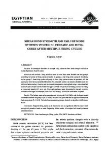
2 Specimen preparation and testing 2.1 Specimen preparation In this study the model material used was made of mixing silica sand, ordinary Portland cement type I and water in 72%, 16%, and 12% proportion by weight respectively. In order to obtain grain to grain contact that cause low tensile strength and high friction angle, high sand content and low cement content were used. The friction angle of the model material determined from direct shear tests was 33o. The ratio of unconfined compressive strength to the tensile strength for material was 12 and the ratio of secant modulus to the unconfined compressive strength was 1100. The procedure developed by Jamil [4] for preparing open non-persistent joints was used in this research with some modification. The sample preparation mold and set-up is shown in Fig. 1. Each sample was cured for 28 days prior to testing. It is important to note that wooden boards were placed on all sides of the sample and secured during handling of the samples to avoid splitting of the jointed sample. A typical sample dimensions are shown in Fig. 2.
Fig. 1. Sample preparation mold and set-up for making open joints
2
MATEC Web of Conferences 103 , 07008 (2017)
DOI: 10.1051/ matecconf/201710307008
ISCEE 2016
Fig. 2. Geometry of the specimens and pre-existing cracks
2.2 Test machine, instrumentation and recording The tests were performed using a 2000kN universal compression machine. The load applied on the sample was measured by load cells installed on the testing machine. The total deformation and the displacements in the vicinity of the joint, were measured by Linear Variable Differential Transducers (LVDT) with a maximum range ±5mm (sensitivity ±0.001mm). Readings of the Load cells and LVDTs were recorded and collected by using a Hewlett Packard data acquisition system.
3 Results and discussion 3.1 Mode of failure 3.1.1 Slightly offset joints (β=22.5o, α=30o) The failure started with the initiation and propagation of the wing crack the wing first and then the secondary cracks initiated at the tips of the joints and propagated to coalesce at a point in the bridge causing sample failure. Crushed and pulverized materials have been noticed on the failure surface. Shear displacement was noticed at the tips of the ligament between the joints. No scale effect was noticed on mode failure. The failed specimen and sketch of the wing and secondary cracks are shown in Fig. 3.
Fig. 3. Crack growth in 22.5º-30º flaws
3
MATEC Web of Conferences 103 , 07008 (2017)
DOI: 10.1051/ matecconf/201710307008
ISCEE 2016 o
o
3.1.2 Offset joints (β= 22.5 , α= 45 ) In these blocks wing cracks propagated from the external flaw tips only and kept growing till the boundary of the block. Coalescence occurred through the growth of secondary crack matching through the flaws. The mode of failure in both sizes was identical. However size shows slight effect on the strength of the joint. The failed specimen and sketch of the wing and secondary cracks are shown in Fig. 4.
Fig. 4. Crack growth in 22.5º-45º flaws
3.1.3 Offset joints (β= 22.5o, α= 60o) In both block sizes the failure initiated by wing cracks propagated from the external flaw tips only, extended to a certain distance from the tips of the joints and opened. Coalescence occurred through the growth of secondary crack matching through the flaws. No scale effect was noticed on mode of failure while strength has affected by the block size. The failed specimen and sketch of the wing and secondary cracks are shown in Fig. 5.
Fig. 5. Crack growth in 22.5º-60º flaws o
o
3.1.4 Overlapped joints (β= 22.5 , α= 90 ) In these blocks failure started as wing cracks propagated from the external and internal flaw tips, they extended and opened. Coalescence occurred through two wing cracks matching through the flaws. The failed specimen and sketch of the wing and secondary cracks are
4
MATEC Web of Conferences 103 , 07008 (2017)
DOI: 10.1051/ matecconf/201710307008
ISCEE 2016
shown in Fig. 6. The results of mode of failure of all tested samples are summarized in Table 1.
Fig. 6. Crack growth in 22.5º-90º flaws Table 1. Mode of block failure with different bridge inclinations
Large sample Small sample
30º Tensile + Shear failure
45º Tensile + Shear failure
60º Tensile failure
90º Tensile failure
Tensile Shear failure
Tensile + Shear failure
Tensile failure
Tensile failure
+
3.2 Effect of scale on strength The current research showed that the scale has slight effect on the strength on the offset non persistent rock joints. Also, the results showed that this effect increased as the bridge inclination angle increases. This behaviour is understood as the mode of failure changes from shear to tension failure as bridge inclination angle increases. As the size of the block increases the intensity of micro flaws also increases which resulted in decreasing the tensile strength of the rock. To eliminate the effect of variation in curing time for the samples, variation in mixes for the samples, and material sources, strength of each sample was normalized by dividing it by the average unconfined compressive strength (f′c) of the cylinders for each sample. The results of normalized uniaxial compressive strength of the large samples and small samples tested are shown in Table 2 and Table 3 respectively. Table 2. Uniaxial compressive strength (MPa) of large samples Large sample
30º
45º
60º
90º
σ1f (MPa)
11
5
6
7
σ1f / fc′
0.92
0.68
0.66
0.58
5
MATEC Web of Conferences 103 , 07008 (2017)
DOI: 10.1051/ matecconf/201710307008
ISCEE 2016 Table 3. Uniaxial compressive strength (MPa) of small samples Small Sample
30º
45º
60º
90º
σ1f (MPa)
13.76
7.46
12.52
12.4
σ1f / fc′
0.98
0.918
0.84
0.81
4 Conclusions The following conclusions may be drawn from the presented research: i) Mode of failure of Rock Bridge varies from shear to tensile failure as the bridge inclination increases. For slightly offset joint (α = 30o or 45o) the failure was due to combined shear and tension failure while it was purely tension for overlapped joints (α = 90o). ii) Wing cracks (Tensile cracks) grew first, and were followed by secondary cracks (Shear cracks) for all the geometries tested, and for both sizes. iii) Size has small or no effect on the mode of bridge failure. iv) Strength is a scale dependent property. As the size of sample increases the strength decreases. The influence of scale becomes more significant as the bridge inclination angle increases.
References [1] S.C. Bandis, A. Lumsden and N. Barton, Experimental studies of scale effects on the shear behavior of rock joints, Int. J. of Rock Mechanics and Mining Sciences, 18, 1-21, (1981) [2] T. Blejwas and F. Hansen, Scale in the shear behavior of joints in welded tuff, Proc. Loen Conf. Rock Joints, Norway, (1990) [3] O. Reyes and H.H. Einstein, Stochastic and centrifuge modeling of jointed rock, Part Ifracturing of jointed rock, Final report submitted to the Air Force Office of Scientific Research and Air Force Engineering Services Center, (1991) [4] S.M. Jamil, Strength of non-persistent rock joints, PhD Thesis, University of Illinois at Urbana-Champaign, IL, United States, (1992) [5] S. Boatang, Mechanics of fractures and inverting bridges in hard rocks, Doctoral Thesis, Royal Institute of Technology, (1993) [6] O. Mughieda, Failure mechanisms and strength of non-persistent rock joints, PhD Thesis, University of Illinois at Urbana-Champaign, IL, United States, (1997) [7] H.C. Wong Robina and K.T. Chau, Crack coalescence in a rock-like material containing two cracks, Int. J. of Rock Mechanics and Mining Sciences, 35(2),147-164, (1998) [8] H. Park and A. Bobet, Crack coalescence in specimens with open and closed flaws: A comparison, Int. J. of Rock Mechanics and Mining Sciences, 46(2), 819-829, (2009) [9] Z. Xiao-Ping, L.N.Y. Wong, Cracking processes in rock-like material containing a single flaw under uniaxial compression: a numerical study based on parallel bondedparticle model approach, Rock Mechanics and Rock Engineering, 45(5), 711-737, (2012) [10] J. Jin, P. Cao and J. Liu, The influence of bridge length on failure patterns of specimens containing two coplanar cracks under uniaxial compression load, Applied Mechanics and Materials,711, 410-413, (2015)
6
MATEC Web of Conferences 103 , 07008 (2017)
DOI: 10.1051/ matecconf/201710307008
ISCEE 2016
[11] O. Mughieda and A. Alzo’ubi, Fracture mechanisms of offset rock joints-A laboratory investigations, Geotechnical and Geological Engineering J., 22, 545-562, (2004) [12] O. Mughieda and I. Khawaldeh, Scale effect on engineering properties of open nonpersistent rock joints under uniaxial loading, RockMEC'2004-VIIth Regional Rock Mechanics Symposium, Sivas, Turkey, (2004) [13] O. Mughieda and I. khawaledh, Scale effect on fracture mechanisms of non-persistent rock joint under uniaxial loading, Geotechnical Engineering J. of Southeast Geotechnical Society, 37(2), (2006)
7