International Journal of Modern Physics A Vol. 22, No. 22 (2007) 3898-3911 © World Scientific Publishing Company
Vkfi^ World Scientific \ ^ www.wor|dscientific.com
Int. J. Mod. Phys. A 2007.22:3898-3911. Downloaded from www.worldscientific.com by TECHNION - ISRAEL INSTITUTE OF TECHNOLOGY on 11/03/15. For personal use only.
SCALING LAWS OF S T R U C T U R E - B A S E D OPTICAL ACCELERATORS
A M I T M I Z R A H I , VADIM K A R A G O D S K Y A N D L E V I S C H A C H T E R Department of Electrical Engineering, Technion - Israel Institute of Technology, Haifa 32000, ISRAEL E-mail:
[email protected] A structure-based laser accelerator harnesses technological progress developed by the laser and optical fiber industries, potentially facilitating a compact and efficient system. In the optical regime, dielectrics sustain higher electric fields and gradients of the order of a few G V / m may become available, but the acceleration structures are different than those used in the microwave regime. Various dielectric structures have been analyzed, and from the pure accelerator parameters perspective (gradient, interaction impedance, group velocity, wake-fields), their performance is of great promise. Operation similar to current linear accelerators may lead to a prohibitively low efficiency. Therefore, including a feedback attached to each module may improve the efficiency from a few percents to higher than 90% - in fact, the efficiency is limited only by the constraints on the stability of the optical system. Single mode operation in the optical regime imposes that at least one of the dimensions of each micro-bunch ought to be sub-micronic leading to a stringent constraint on the emittance and thus on the luminosity. Attempting to increase the latter, imposes high energy density in the vacuum tunnel as well as in its adjacent dielectric layer(s). This, in turn, is bounded by the maximum stress, temperature increase and heat dissipation, dielectrics can sustain at these scales.
1. Introduction Motivated by the availability of solid-state lasers with increasing wall-plug to light efficiencies, optical acceleration of charged particles is a subject of growing interest. Acceleration is facilitated by laser light rather than by microwave radiation, and accordingly, the acceleration structure must be made of dielectric materials as these have lower loss and are less susceptible to breakdown comparing to their metallic counterparts. An example of an open optical structure is the L E ^ P 1 crossed laser beam experiment where the interaction between the crossed laser beams and the particles is limited by slits to satisfy the Lawson-Woodward theorem 2,3 . Another example is the travelling wave acceleration structure, where a laser pulse is guided in a 3898
Int. J. Mod. Phys. A 2007.22:3898-3911. Downloaded from www.worldscientific.com by TECHNION - ISRAEL INSTITUTE OF TECHNOLOGY on 11/03/15. For personal use only.
Scaling Laws of Structure-Based Optical Accelerators 3899
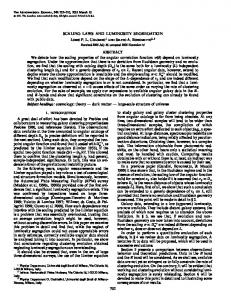
dielectric structure with a vacuum tunnel bored in its center. This concept can be implemented by a two-dimensional photonic band-gap structure 4 , and recently, it was suggested 5 to use Bragg reflection waveguides 6 ' 7 ' 8 , designed specifically for the speed-of-light mode. It was demonstrated 5 that optical Bragg acceleration structures, either planar or cylindrical, having typical transverse dimensions of a few microns, exhibit high performance as acceleration structures and, therefore, seem to be promising candidates for future optical accelerators; Fig. 1 illustrates the planar version of such a structure. The laser light is confined in a vacuum core of width 2Di nt , so that the wave propagates along the z axis, and no variations are assumed along the y axis (d/dy = 0). The core is surrounded by dielectric layers with alternating permittivity, having a width equal to the transverse quarter-wavelength [\/{A^/er — 1)] with the exception of the innermost layer. This first layer is a matching layer and it plays a crucial role facilitating the structure to support the speed-of-light TM mode required for the acceleration process.
Figure 1.
Schematic of a planar Bragg acceleration structure.
Transition from operation at radiation wavelengths of a few centimeters to a few microns requires examining a wide spectrum of phenomena which are insignificant in the former regime. For example, structures that operate at a wavelength 0 f a few centimeters are machined today with an accuracy of microns. In the future, it will not be possible to maintain a ratio of 4-5 orders of magnitude between the operating wavelength and the achievable tolerance, since this would entail engineering of a surface at the atomic level. As a result, the size of irregularities may be of the same order of magnitude as the micro-bunches, and they may generate wake fields9,10 that, in turn, may alter the dynamics of electrons. Fortunately, the electromagnetic properties of materials at wavelengths that are s ig n ifi c a n tly smaller than 0.1 /im do not differ dramatically from these of the vacuum.
Int. J. Mod. Phys. A 2007.22:3898-3911. Downloaded from www.worldscientific.com by TECHNION - ISRAEL INSTITUTE OF TECHNOLOGY on 11/03/15. For personal use only.
3900
A. Mizrahi, V. Karagodsky & L. Schdchter
Consequently, a reduction on the sensitivity to manufacturing tolerances may be expected. As a central component of a future optical accelerator, the acceleration structure, ought to withstand the manifestations of the two most important constraints imposed by the machine specifications, namely, the luminosity and the operating gradient. Being a measure of the number of colliding particles per second at the interaction point, the luminosity sets the lower limit to the energy level the particles are exposed to. Together with the operating gradient and the constraint of single mode operation, they determine the minimal electromagnetic energy density in the acceleration tunnel and its close vicinity. While obviously the average number of particles per second is at least as in a machine designed to operate at microwave wavelengths, in an optical acceleration structure, the volume where most of the electromagnetic energy is confined, is reduced by several orders of magnitude. Consequently, the potential impact of conversion efficiency, electromagnetic stress on the structure, heat flow or temperature increase may become a significant obstacle, and it is our goal in this study to determine the main scaling laws of these processes.
2. Efficiency C o n s i d e r a t i o n s In an acceleration structure driven by a microwave source, a typical bunch consists of an order of 10 10 electrons and its size is measured on 1 mm scale. In the optical range, the transverse dimensions are reduced by 2-3 orders of magnitude implying that if the particles' density is maintained the same, the number of accelerated electrons is reduced by 6-7 orders of magnitude. Consequently, following the same approach as in the microwave regime, may lead to prohibitively low efficiencies since each laser pulse accelerates only a few thousand electrons. As a result, for maintaining the same luminosity, the repetition rate ought to be increased correspondingly. Alternatively, it is possible to accelerate a train of micro-bunches rather than a single micro-bunch and release the constraint on the repetition rate. Before further discussing this concept, let us briefly review 11 the efficiency estimate of an acceleration module of length d driven by an average laser power PL generating a gradient Go at the location of the electrons. By virtue of the linearity of Maxwell's equations, these two quantities are related, and the so-called interaction impedance, Z\nt = | G O A | 2 / P L , characterizes any acceleration structure operating at a frequency corresponding to a vacuum wavelength A. This laser pulse accelerates a point-charge (q)
Int. J. Mod. Phys. A 2007.22:3898-3911. Downloaded from www.worldscientific.com by TECHNION - ISRAEL INSTITUTE OF TECHNOLOGY on 11/03/15. For personal use only.
Scaling Laws of Structure-Based
Optical Accelerators
3901
that as it moves in an arbitrary acceleration structure, it generates an electromagnetic wake. Associated with this wake there is a decelerating electric field (-Edec) which again, by virtue of the linearity of Maxwell's equations, must be proportional to the charge, namely, E^ec = ^#> where the value of K depends on the details of the structure, and it will be referred to as the wake-coefficient. By virtue of the fundamental loading theorem, the amplitude of the trailing wake is twice this value, namely, E% — 2E^ec = 2nq. In case of a uniform dielectric medium filling the entire space except a vacuum tunnel of radius R, along which the point-charge propagates, the wake-coefficient is K = l/(27T£o-R2); for more realistic structures the reader is referred to detailed analysis of Bragg acceleration structure in Ref 5. In a closed structure, the wake generated by the bunch has projections on each one of the eigen-modes of the structure. Bane and Stupakov 12 have discussed the connection between the various parameters (group velocity c/3gr and interaction impedance Z[nt) and the projection of the wake on the fundamental (superscript F) mode 1 - /3gr v ^ 7 ^ 47Te0A2 * In other words, this is the coefficient that given the charge of the bunch, determines the amplitude of the fundamental mode generated by the bunch ^(F) _ 2ft( F )g). In the absence of an accelerating gradient Go? the electron bunch is decelerated along a distance d in the structure, and the loss of kinetic energy is A?7KIN = —q2K>d. Consequently, when the gradient is not zero, the net change in the kinetic energy of the bunch traversing the same structure is given by AUKIN = Q(GO ~ Q^)- As a reference, the total electromagnetic energy stored in the structure is Z7EM = PL^EM wherein TEM = (d/c)(l//3 g r ~ !)• This last expression takes into consideration the requirement that the point-charge and the electromagnetic pulse ought to overlap during the time the former spends in the structure. With these two energy definitions, the efficiency of the acceleration process may be determined by A [/KIN _ 'I —
jTTj
UEM
—
— '/max ??max
M (q0 - q) 2o QO
'
\
)
where go — Go/K is the charge for which the effective gradient vanishes, and the maximum value of the efficiency is 7] max = KSFI / K occurring for q = «opt = 9o/2. As a typical example, consider the parameters of a photonic band-gap structure as calculated in Ref. 4: Z\nt ~ 20 O, /?gr ~ 0.6 and R ~ 0.7A;
Int. J. Mod. Phys. A 2007.22:3898-3911. Downloaded from www.worldscientific.com by TECHNION - ISRAEL INSTITUTE OF TECHNOLOGY on 11/03/15. For personal use only.
3902 A. Mizrahi, V. Karagodsky & L. Schdchter
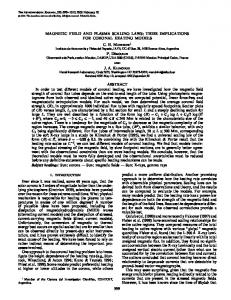
according to these values the maximum efficiency is 6%. Assuming that the threshold for breakdown limits the power to 7 kW, the optimal number of electrons to be accelerated for reaching this efficiency is 6 x 10⁴. Evidently, considerations of energy spread will lead to charges and efficiencies below these optimum values. Although this result relies on an idealized model, it hints what the possible solution may be: first, we observe that more than 90% of the electromagnetic energy is wasted, and therefore, by "recycling" part of this energy we may improve significantly the efficiency of an optical system. Moreover, the analytic result from the above reflects the fact that the efficiency is determined by the relative projection of the wake on the fundamental mode. This quantity may be enhanced by splitting the bunch into a train of microbunches each one separated by the wavelength of the fundamental - see Fig. 2. What makes the implementation of these two concepts feasible, is the fact that rather than accelerating a single bunch, the wake being broadband and thus useless from the perspective of energy recycling, a macrobunch consisting of many hundreds of micro-bunches is accelerated - each micro-bunch being one laser wavelength (A) apart from its neighbor. This makes the wake virtually coherent with the laser field. Consequently, at the output of a given travelling wave acceleration module, the two field components (laser and wake) are practically inseparable and the total electromagnetic field may be extracted out of the acceleration structure, amplified by an active medium and re-injected into the travelling wave acceleration module. External Laser
Figure 2. erator.
Recovery scheme for achieving high efficiency operation of an optical accel-
Obviously, the accelerating field ought to be tapered in order to compensate for the varying beam-loading. In practice, for a self-sustained solution
Int. J. Mod. Phys. A 2007.22:3898-3911. Downloaded from www.worldscientific.com by TECHNION - ISRAEL INSTITUTE OF TECHNOLOGY on 11/03/15. For personal use only.
Scaling Laws of Structure-Based
Optical Accelerators
3903
of the field in a given acceleration module, it is necessary to provide from the outside a tapered field whereas all the energy loss has to be compensated by the feedback loop. However, these details and many more were considered in Ref. 11 and will be omitted here. The outcome of this analysis had demonstrated that indeed by combining multiple micro-bunches and a feedback loop it is possible to enhance both the efficiency as well as the number of electrons to be accelerated. Two important constraints are imposed: first the length of the accelerating module needs to be equal to the bunch length (d ^ MA). Second, the group velocity which makes the external laser pulse to have the simplest shape is /3 gr ^ 0 . 5 . According to the (loaded) quality factor of each module the efficiency may exceed the 90% accelerating in the process about 1000 micro-bunches each one consisting of a number of electrons limited by the (technological) ability to taper the external laser pulse. 3. Electromagnetically Induced Stress in a Planar Bragg Structure The high energy electromagnetic field guided within an optical acceleration structure gives rise to forces on the dielectric materials sometimes referred to as "radiation pressure". In this section, we shall examine these forces on the dielectric layers of the planar optical Bragg acceleration structure. Our treatment here relies on macroscopic electromagnetic concepts, where the material is represented by a polarization density, with associated polarization volume or surface currents and charges. The local Lorentz force may then be calculated directly, as resulting from the interaction of the electromagnetic field and these effective charges and currents. Particularly, at the frequency of laser light, the time-averaged force is the quantity of interest. Let us consider a planar acceleration structure guiding laser light and examine the time-averaged forces on this structure. In the vacuum core, the speed-of-light TM mode guided by the acceleration structure, assuming a time-dependence of exp (ju;£), is of the form5 Ez = E0exp \-j-zj Ex = E0 (j-x)
exp y-J-z)
Hy = — (j-x) T]0 \
C
, >
exp l-j-z) /
V
C
(3)
. /
The total transverse force exerted on the mirrors may be found by integrat-
3904
A. Mizrahi, V. Karagodsky & L. Schdchter
ing the time-averaged Maxwell stress-tensor 13 over a closed surface. Within the vacuum core, the time-averaged Maxwell stress-tensor component (Txx) for a TM mode reads (Txx) = -so\Ex\
—
-SQ\EZ\
— -fio\Hy\
,
(4)
Int. J. Mod. Phys. A 2007.22:3898-3911. Downloaded from www.worldscientific.com by TECHNION - ISRAEL INSTITUTE OF TECHNOLOGY on 11/03/15. For personal use only.
and given the expressions in Eq. (3), we are left with (Txx) = -^eol-Eol 2 .
(5)
Enclosing one mirror by a rectangular surface, only the Txx component contributes to the integral, as the Txz component has zero contribution due to symmetry, and the Txy component is identically zero. Assuming that the laser field decays to zero at x = ±oo, the time-averaged transverse pressure exerted by the guided mode on the Bragg mirror located at x = Dint is {Fx) = ±e0\E0\2.
(6)
Hence, for a given accelerating gradient EQ, the total pressure is repelling and is independent of the details of the structure, that could be, for example, a dielectric loaded metallic transmission line. Assuming that the gradient of interest is Eo = 1 GV/m, the total pressure is (Fx) ~ 2.2 x 1(T 6 N//2m 2 ~ 2.2 x 10⁶ N/m 2 - we shall discuss the implications of this result in the last section. Beyond the total pressure exerted by the radiation field on the confining walls, it is important evaluate the force(s) on each dielectric layer as well as the stress occurring at the interface between two layers. Evaluation of the time-averaged volume force densities of the accelerating TM mode is performed next based on the expression for the Lorentz force-density. Its transverse component may be shown to be given by 1, leading to the conclusion that the effect of these forces is to pull each of the two layers at the interface towards the other. The total pressure is the sum of all transverse forces, and explicitly Xv+l
w =£
{Fx,u)+
J
dx(fx(x))
(12)
i/=0
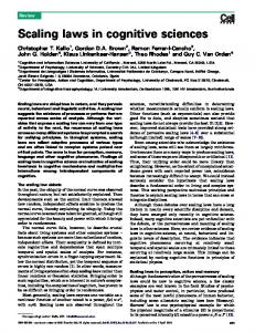
where xv denotes the boundary between layer v and layer v + 1, and v = 0 denotes the core. Practically, the above equation may be verified numerically by carrying out the summation up to some layer where the fields have sufficiently decayed to be considered negligible. The transverse volume force density and the surface forces for a structure made of Si02 (sr = 1.452) and Si (sr = 3.452) and core half-width D'mt — 0.3AQ are shown in Fig. 3. The frames in the left column correspond to a structure having the SiC>2 as the matching layer adjacent to the core, and the right column corresponds to a structure with Si as the layer adjacent to the core. When the lower refractive index is used for the matching layer, the maximum of the volume force density is obtained inside the second layer [Fig. 3 (c)], whereas in the second case, the maximum is obtained inside the matching layer [Fig. 3 (d)]. The surface force density {FXiU), which peaks at the vacuum-dielectric interface, is shown in Fig. 3 (e)-(f) together with the one-sided force densities (Fx } and (Fx }• Inside the periodic part of the Bragg mirror, Ex vanishes every other interface 5 , and, accordingly, all the 3 surface force densities vanish as well.
Int. J. Mod. Phys. A 2007.22:3898-3911. Downloaded from www.worldscientific.com by TECHNION - ISRAEL INSTITUTE OF TECHNOLOGY on 11/03/15. For personal use only.
3906 A. Mizrahi, V. Karagodsky & L. Schachter
Figure 3. Force profiles in Bragg structures with SiC>2 and Si layers. The electromagnetic field (a-b), volume force density (c-d), and surface force densities (e-f), are shown.
Let us briefly examine the implications of the above results on the acceleration structure. Assuming that one Bragg mirror in the structure is of dimensions 1 mm x 1 mm x 50 /im and EQ = 1 GV/m, the total transverse force on the mirror is 2.2 N. If we consider a material density of about 2 gr/cm 3 , we obtain that this force is by no means negligible since it is 6 orders of magnitude larger than the gravitational force on the mirror. On the other hand, from the perspective of material strength and the possibility of crack formation, it is reasonable to assume that a pressure below E/TTJ where E is Young's modulus, may be sustained without damage to the structure 14 . Young's modulus for Si02 is 72.6 GN/m 2 , whereas for Si it is 162 GN/m 2 (see Ref. 15). Since the total pressure in our case is of the order of 106 N/m 2 , the electromagnetic forces are about 4 orders of magnitude below the theoretical threshold E/TT.
Scaling Laws of Structure-Based
Optical Accelerators
3907
Int. J. Mod. Phys. A 2007.22:3898-3911. Downloaded from www.worldscientific.com by TECHNION - ISRAEL INSTITUTE OF TECHNOLOGY on 11/03/15. For personal use only.
4. Thermal Considerations As indicated in the Introduction, reduction of the optical wavelength entails a corresponding increase in the energy density in the vacuum channel as well as in its close vicinity. Naturally, the question we are about to briefly address in this section is the impact of the optical field on the thermal processes in an acceleration structure 16 . As in the second section, we consider a planar optical Bragg acceleration structure as analyzed in Ref. 5. This structure will form the foundation of a model that allows to establish a set of approximate analytic expressions describing the temperature and the heat flux distributions in typical optical acceleration structures. Starting from basic principles, it is well known that the temperature distribution is determined by the diffusion equation which reads
(6
1
2\
.„
1
wherein AT is the temperature change, ( T T [ W / ( 0 K H I ) ] is the thermal conductivity, D[sec/m2] is the thermal diffusion coefficient and PiOSs is the dissipated power density. The following set of approximations allows us to significantly simplify the solution of Eq. (13) without notably affecting its accuracy: • The temperature and the dissipated power density variations are assumed to be one-dimensional in the cross-sectional direction. • The periodic dielectric layers, which have alternating thermal conductivities int
(21) Figure 4 is a representative result which compares the exact solution of Eq. (13) and the approximations presented above. It is quite evident that the exact and the approximate solutions are virtually indistinguishable. Further analysis shows that for h = 3 W/(°Kcm 2 ) the maximal temperature in a Silica-Zirconia structure is 356 x 10 7 tan5i[°K] and the maximal heat-flux is 9.22 x 10 9 tan#i[W/em 2 ], while in the Silica-Silicon structure these quantities are 66.4 x 10 7 tan5i[°K] and 1.74 x 10 9 tan5i[W/em 2 ], wherein tan