5.1 Fault Tolerance Overheads with MXR (Compared to NFT) for Different Applications. ...... ios for application A2, which is composed of 6 processes, P1 to P6,.
Linköping Studies in Science and Technology Dissertation No. 1290
Scheduling and Optimization of Fault-Tolerant Distributed Embedded Systems by
Viacheslav Izosimov
Department of Computer and Information Science Linköpings universitet SE-581 83 Linköping, Sweden Linköping 2009
ISBN
978-91-7393-482-4 ISSN 0345-7524 PRINTED IN LINKÖPING, SWEDEN BY LINKÖPINGS UNIVERSITET
COPYRIGHT © 2009 VIACHESLAV IZOSIMOV
To Evgenia
Abstract S AFETY - CRITICAL APPLICATIONS have to function correctly and deliver high level of quality-of-service even in the presence of faults. This thesis deals with techniques for tolerating effects of transient and intermittent faults. Reexecution, software replication, and rollback recovery with checkpointing are used to provide the required level of fault tolerance at the software level. Hardening is used to increase the reliability of hardware components. These techniques are considered in the context of distributed real-time systems with static and quasi-static scheduling. Many safety-critical applications have also strict time and cost constrains, which means that not only faults have to be tolerated but also the constraints should be satisfied. Hence, efficient system design approaches with careful consideration of fault tolerance are required. This thesis proposes several design optimization strategies and scheduling techniques that take fault tolerance into account. The design optimization tasks addressed include, among others, process mapping, fault tolerance policy assignment, checkpoint distribution, and trading-off between hardware hardening and software reexecution. Particular optimization approaches are also proposed to consider debugability requirements of faulttolerant applications. Finally, quality-of-service aspects have been addressed in the thesis for fault-tolerant embedded systems with soft and hard timing constraints. The proposed scheduling and design optimization strategies have been thoroughly evaluated with extensive experiments. The experimental results show that considering fault tolerance during system-level design optimization is essential when designing cost-effective and high-quality fault-tolerant embedded systems.
Acknowledgements I WOULD LIKE to thank my advisors Prof. Zebo Peng, Prof. Petru Eles, and Dr. Paul Pop for guiding me through years of graduate studies and for their valuable comments on this thesis. Despite having four often contradictory points of view, after long discussions, we could always find a common agreement. Special thanks to Dr. Ilia Polian from the University of Freiburg for his good sense of humour and productive collaboration resulted in the hardware hardening part of this thesis. Many thanks to the CUGS graduate school for supporting my research and providing excellent courses, and to the ARTES++ graduate school for supporting my travelling. I would also like to express many thanks to my current and former colleagues at ESLAB and IDA for creating nice and friendly working environment. I will never forget our julbords and fikas. I am also grateful to my family and friends who have supported me during work on this thesis. I would like to exceptionally thank my parents, Victor Izosimov and Galina Lvova, who have been encouraging me during many long years of my studies. Finally, I devote this thesis to my beloved wife, Yevgeniya Kyselova, for her love, patience, and constant support. Linköping, November 2009
Viacheslav Izosimov
Contents
I. Preliminaries: 1. Introduction .........................................................................1 1.1 Motivation ........................................................................2 1.1.1 Transient and Intermittent Faults ............................. 2 1.1.2 Fault Tolerance and Design Optimization.................. 4 1.2 Contributions ...................................................................6 1.3 Thesis Overview...............................................................8 2. Background and Related Work ........................................11 2.1 Design and Optimization ...............................................11 2.2 Fault Tolerance Techniques ...........................................14 2.2.1 Error Detection Techniques ........................................ 14 2.2.2 Re-execution ................................................................. 16 2.2.3 Rollback Recovery with Checkpointing ...................... 17 2.2.4 Active and Passive Replication ................................... 19 2.2.5 Hardening .................................................................... 21 2.3 Transparency ...................................................................22 2.4 Design Optimization with Fault Tolerance ....................24 2.4.1 Design Flow with Fault Tolerance Techniques .......... 29 3. Preliminaries .......................................................................33 3.1 System Model ..................................................................33 3.1.1 Hard Real-Time Applications...................................... 33
3.1.2 Mixed Soft and Hard Real-Time Applications ............35 3.1.3 Basic System Architecture........................................... 36 3.1.4 Fault Tolerance Requirements .................................... 37 3.1.5 Adaptive Static Cyclic Scheduling...............................38 3.1.6 Quality-of-Service Model.............................................. 40
3.2 Software-level Fault Tolerance Techniques....................42 3.2.1 Recovery in the Context of Static Cyclic Scheduling.. 44
II. Hard Real-Time Systems: 4. Scheduling with Fault Tolerance Requirements .........49 4.1 Performance/Transparency Trade-offs ...........................50 4.2 Fault-Tolerant Conditional Process Graph ....................54 4.2.1 FTPG Generation ......................................................... 58 4.3 Conditional Scheduling ...................................................64 4.3.1 Schedule Table.............................................................. 64 4.3.2 Conditional Scheduling Algorithm ..............................68 4.4 Shifting-based Scheduling...............................................73 4.4.1 Shifting-based Scheduling Algorithm .........................74 4.5 Experimental Results ......................................................81 4.5.1 Case Study .................................................................... 84 4.6 Conclusions ......................................................................85 5. Mapping and Fault Tolerance Policy Assignment .......87 5.1 Fault Tolerance Policy Assignment.................................88 5.1.1 Motivational Examples ................................................ 89 5.2 Mapping with Fault Tolerance ........................................92 5.2.1 Design Optimization Strategy .................................... 93 5.2.2 Scheduling and Replication ......................................... 94 5.2.3 Optimization Algorithms ............................................. 96 5.3 Experimental Results ......................................................101 5.4 Conclusions ......................................................................105 6. Checkpointing-based Techniques ..................................107 6.1 Optimizing the Number of Checkpoints .........................107 6.1.1 Local Checkpointing Optimization..............................108 6.1.2 Global Checkpointing Optimization............................111 6.2 Policy Assignment with Checkpointing ..........................113
6.2.1 Optimization Strategy ................................................. 115 6.2.2 Optimization Algorithms............................................. 116
6.3 Experimental Results .....................................................119 6.4 Conclusions ......................................................................123
III. Mixed Soft and Hard Real-Time Systems: 7. Value-based Scheduling for Monoprocessor Systems 127 7.1 Utility and Dropping .......................................................128 7.2 Single Schedule vs. Schedule Tree..................................131 7.3 Problem Formulation.......................................................136 7.4 Scheduling Strategy and Algorithms..............................137 7.4.1 Schedule Tree Generation ........................................... 138 7.4.2 Generation of f-Schedules............................................ 140 7.4.3 Switching between Schedules .................................... 142 7.5 Experimental Results ......................................................143 7.6 Conclusions ......................................................................145 8. Value-based Scheduling for Distributed Systems .......147 8.1 Scheduling........................................................................148 8.1.1 Signalling and Schedules ............................................ 149 8.1.2 Schedule Tree Generation ........................................... 153 8.1.3 Switching between Schedules ..................................... 157 8.2 Experimental Results .....................................................157 8.3 Conclusions ......................................................................163
IV. Embedded Systems with Hardened Components: 9. Hardware/Software Design for Fault Tolerance .........167 9.1 Hardened Architecture and Motivational Example.......168 9.2 System Failure Probability (SFP) Analysis....................170 9.2.1 Computation Example................................................. 173 9.3 Conclusions ......................................................................175 10. Optimization with Hardware Hardening ....................177 10.1 Motivational Example ...................................................178 10.2 Problem Formulation.....................................................180 10.3 Design Strategy and Algorithms ..................................181
10.4 Mapping Optimization .................................................185 10.5 Hardening/Re-execution Optimization ........................187 10.6 Scheduling......................................................................189 10.7 Experimental Results ...................................................190 10.8 Conclusions ....................................................................194
V. Conclusions and Future Work: 11. Conclusions and Future Work ......................................197 11.1 Conclusions ...................................................................198 11.1.1 Hard Real-Time Systems ........................................... 198 11.1.2 Mixed Soft and Hard Real-Time Systems ................200 11.1.3 Embedded Systems with Hardened Hardware Components ................................................................ 201 11.2 Future Work ..................................................................201
Appendix I ...................................................................... 205 Appendix II ..................................................................... 207 Appendix III .................................................................. 211
List of Notations ............................................................ 219 List of Abbreviations ................................................... 229 Bibliography................................................................... 233
List of Figures
2.1 2.2 2.3 2.4 2.5 2.6
Generic Design Flow............................................................12 Re-execution.........................................................................17 Rollback Recovery with Checkpointing ..............................18 Active Replication and Primary-Backup ............................20 Hardening ............................................................................22 Design Flow with Fault Tolerance ......................................30
3.1 3.2 3.3 3.4 3.5 3.6 3.7 3.8
Hard Real-Time Application ...............................................34 Mixed Soft and Hard Real-Time Application .....................35 A Static Schedule.................................................................39 Utility Functions and Dropping..........................................40 Fault Model and Fault Tolerance Techniques ....................42 Transparency and Frozenness ............................................44 Alternative Schedules for Re-execution .............................45 Alternative Schedules for Rollback Recovery with Checkpointing ......................................................................45
4.1 4.2 4.3 4.4
Application with Transparency ..........................................51 Trade-off between Transparency and Performance...........53 Fault-Tolerant Process Graph.............................................55 Generation of FTPG ............................................................59
4.5 4.6 4.7 4.8 4.9 4.10 4.11 4.12 4.13 4.14 4.15 4.16 5.1 5.2 5.3 5.4 5.5 5.6 5.7 5.8 5.9 6.1 6.2 6.3 6.4 6.5 6.6
FTPG Generation Steps (1).................................................60 FTPG Generation Steps (2).................................................63 Conditional Schedule Tables...............................................66 Signalling Messages ............................................................67 Fault-Tolerant Schedule Synthesis Strategy .....................69 Alternative Traces Investigated by FTPGScheduling for the Synchronization Node ...................................................71 Conditional Scheduling .......................................................72 Ordered FTPG .....................................................................75 Generation of Root Schedules .............................................77 Example of a Root Schedule................................................78 Example of an Execution Scenario .....................................79 Extracting Execution Scenarios..........................................80 Policy Assignment: Re-execution + Replication .................88 Comparison of Replication and Re-execution.....................90 Combining Re-execution and Replication ..........................92 Mapping and Fault Tolerance .............................................93 Design Optimization Strategy for Fault Tolerance Policy Assignment ...............................94 Scheduling Replica Descendants ........................................95 Moves and Tabu History .....................................................98 Tabu Search Algorithm for Optimization of Mapping and Fault Tolerance Policy Assignment ............................99 Comparing MXR with MX, MR and SFX ...............................104 Locally Optimal Number of Checkpoints ...........................108 Globally Optimal Number of Checkpoints ........................111 Policy Assignment: Checkpointing + Replication ..............113 Design Optimization Strategy for Fault Tolerance Policy Assignment with Checkpointing.............116 Restricting the Moves for Setting the Number of Checkpoints ...............................................118 Deviation of MC and MCR from MC0 with Varying Application Size ............................................120
6.7 6.8
Deviation of MC and MCR from MC0 with Varying Checkpointing Overheads.............................121 Deviation of MC and MCR from MC0 with Varying Number of Transient Faults .........................122
7.1 7.2 7.3 7.4 7.5 7.6 7.7 7.8
Application Example with Soft and Hard Processes .........128 Utility Functions and Dropping..........................................129 Scheduling Decisions for a Single Schedule.......................132 A Schedule Tree ...................................................................135 General Scheduling Strategy ..............................................137 Schedule Tree Generation...................................................139 Single Schedule Generation ................................................141 Comparison between FTTreeGeneration, FTSG and FTSF .....144
8.1 8.2 8.3
Signalling Example for a Soft Process................................150 Signalling Example for a Hard Process..............................152 Schedule Tree Generation in the Distributed Context ..................................................154 Single Schedule Generation in the Distributed Context ..................................................155 Experimental Results for Schedule Tree Generation in the Distributed Context ..................................................160
8.4 8.5
9.1
9.3
Reduction of the Number of Re-executions with Hardening ...................................................................169 A Fault Scenario as a Combination with Repetitions...................................................................171 Computation Example with SFP Analysis.........................174
10.1 10.2 10.3 10.4 10.5
Selection of the Hardened Hardware Architecture ...........179 Optimization with Hardware Hardening ...........................181 General Design Strategy with Hardening..........................183 Mapping Optimization with Hardening .............................186 Hardening Optimization Algorithm ...................................188
9.2
10.6 Accepted Architectures as a Function of Hardening Performance Degradation ................................191 10.7 Accepted Architectures for Different Fault Rates with ArC = 20 for HPD = 5% and HPD = 100%..........................193 A.1 The Cruise Controller Process Graph.................................206
List of Tables
4.1
Fault Tolerance Overhead (CS) ...........................................82
4.2 4.3
Memory Requirements (CS) ................................................82 Memory Requirements (SBS) ..............................................84
5.1
Fault Tolerance Overheads with MXR (Compared to NFT) for Different Applications....................................................102
5.2
Fault Tolerance Overheads due to MXR for Different Number of Faults in the Applications of 60 Processes Mapped on 4 Computation Nodes.......................................103
8.1
Normalized Utility (Un = UFTTree/UfN×100%) and the Number of Schedules (n)........................................158
10.1 Accepted Architectures with Different Hardening Performance Degradation (HPD) and with Different Maximum Architecture Costs (ArC) for the Medium FR Technology ................................................192
PART I Preliminaries
Chapter 1 Introduction
T HIS THESIS DEALS with the analysis and optimization of safety-critical real-time applications implemented on fault-tolerant distributed embedded systems. Such systems are responsible for critical control functions in aircraft, automobiles, robots, telecommunication and medical equipment. Therefore, they have to function correctly and meet timing constraints even in the presence of faults. Faults in distributed embedded systems can be permanent, intermittent or transient. Permanent faults cause long-term malfunctioning of components, while transient and intermittent faults appear for a short time. The effects of transient and intermittent faults, even though they appear for a short time, can be devastating. They may corrupt data or lead to logic miscalculations, which can result in a fatal failure or dramatic quality-ofservice deterioration. Transient and intermittent faults appear at a rate much higher than the rate of permanent faults and, thus, are very common in modern electronic systems. Transient and intermittent faults can be addressed in hardware with hardening techniques, i.e., improving the hardware technology and architecture to reduce the fault rate, or in soft1
C HAPTER 1
ware. We consider hardware-based hardening techniques and several software-based fault tolerance techniques, including reexecution, software replication, and rollback recovery with checkpointing. Safety-critical real-time applications have to be implemented such that they satisfy strict timing requirements and tolerate faults without exceeding a given amount of resources. Moreover, not only timeliness, reliability and cost-related requirements have to be considered but also other issues such as debugability and testability have to be taken into account. In this introductory chapter, we motivate the importance of considering transient and intermittent faults during the design optimization of embedded systems. We introduce the design optimization problems addressed and present the main contributions of our work. We also present an overview of the thesis with short descriptions of the chapters.
1.1 Motivation In this section we discuss the main sources of transient and intermittent faults and how to consider such faults during design optimization. 1.1.1 TRANSIENT AND INTERMITTENT FAULTS There are several reasons why the rate of transient and intermittent faults is increasing in modern electronic systems, including high complexity, smaller transistor sizes, higher operational frequency, and lower voltage levels [Mah04, Con03, Har01]. The first type of faults, transient faults, cause components to malfunction for a short time, leading to corruption of memory or miscalculations in logic, and then disappear [Sto96, Kor07]. A good example of a transient fault is the fault caused by solar radiation or electromagnetic interference. The rate of transient 2
I NTRODUCTION
faults is often much higher compared to the rate of permanent faults. Transient-to-permanent fault ratios can vary between 2:1 and 50:1 [Sos94], and more recently 100:1 or higher [Kop04]. Automobiles, for example, are largely affected by transient faults [Cor04a, Han02] and proper fault tolerance techniques against transient faults are needed. Another type of faults, which we consider, are intermittent faults. Although an intermittent fault manifests itself similar to a transient fault, i.e., appears for a short time and then disappears, this fault will re-appear at some later time [Sto96, Kor07]. For example, intermittent faults can be triggered by one improperly placed device affecting other components through a radio emission or via a power supply. One such component can also create several intermittent faults at the same time. It is observed that already now more than 50% of automotive electronic components returned to the vendor have no physical defects, and the malfunctioning is the result of intermittent and transient faults produced by other components [Kim99]. Causes of transient and intermittent faults can vary a lot. There exist several possible causes of these faults, including: • (solar) radiation (mostly neutrons) that can affect electronic systems not only on the Earth orbit and in space but also on the ground [Sri96, Nor96, Tan96, Ros05, Bau01, Vel07]; • electromagnetic interference by mobile phones, wireless communication equipment [Str06], power lines, and radars [Han02]; • lightning storms that can affect power supply, current lines, or directly electronic components [Hei05]; • internal electromagnetic interference [Wan03]; • crosstalk between two or more internal wires [Met98]; • ion particles in the silicon that are generated by radioactive elements naturally present in the silicon [May78]; • temperature variations [Wei04]; • power supply fluctuations due to influence of internal components [Jun04]; and 3
C HAPTER 1
• loose connectors [Pet06], for example, between a network cable and the distributed components attached to it. From the fault tolerance point of view, transient faults and intermittent faults manifest themselves in a similar manner: they happen for a short time and then disappear without causing a permanent damage. Hence, fault tolerance techniques against transient faults are also applicable for tolerating intermittent faults and vice versa. Therefore, from now, we will refer to both types of faults as transient faults and we will talk about fault tolerance against transient faults, meaning tolerating both transient and intermittent faults. 1.1.2 FAULT TOLERANCE AND DESIGN OPTIMIZATION Safety-critical applications have strict time and cost constraints and have to deliver a high level of quality of service, which means that not only faults have be to tolerated but also the imposed constraints have to be satisfied. Traditionally, hardware replication was used as a fault tolerance technique against transient faults. For example, in the MARS [Kop90, Kop89] approach each fault-tolerant component is composed of three computation units, two main units and one shadow unit. Once a transient fault is detected, the faulty component must restart while the system is operating with the nonfaulty component. This architecture can tolerate one permanent fault and one transient fault at a time, or two transient faults. Another example is the XBW [Cla98] architecture, where hardware duplication is combined with double process execution. Four process replicas are run in total. Such an architecture can tolerate either two transient faults or one transient fault with one permanent fault. Interesting implementations can be also found in avionics. For example, an airborne architecture, which contains seven hardware replicas that can tolerate up to three transient faults, has been studied in [Als01] based on the flight control system of the JAS 39 Gripen aircraft. However, this solu-
4
I NTRODUCTION
tion is very costly and can be used only if the amount of resources is virtually unlimited. In other words, existing architectures are either too costly or are unable to tolerate multiple transient faults. In order to reduce cost, other techniques are required such as software replication [Xie04, Che99], recovery with checkpointing [Jie96, Pun97, Bar08, Yin03, Yin06, Aya08, Kri93], and reexecution [Kan03a]. However, if applied in a straightforward manner to an existing design, software-based techniques against transient faults introduce significant time overheads, which can lead to unschedulable solutions. Time overhead can be reduced with hardening techniques [Gar06, Hay07, Moh03, Zha06, Zho06, Zho08], which reduce the transient fault rate and, hence, the number of faults propagated to the software level. On the other hand, using more reliable and/or faster components, or a larger number of resources, may not be affordable due to cost constraints. Therefore, efficient design optimization techniques are required, in order to meet time and cost constraints within the given resources, in the context of fault-tolerant systems. Transient faults are also common for communication channels, even though we do not deal with them in this thesis. We assume that transient faults on the bus are addressed at the communication level, for example, with the use of efficient error correction codes [Pir06, Bal06, Ema07], through hardware replication of the bus [Kop03, Sil07], and/or acknowledgements/ retransmissions [Jon08]. Solutions such as a cyclic redundancy code (CRC) are implemented in communication protocols available on the market [Kop93, Kop03, Fle04].
5
C HAPTER 1
1.2 Contributions In our approach, an embedded application is represented as a set of soft and hard real-time processes [But99] communicating by sending messages. Hard processes represent time-constrained parts of the application, which must be always executed and meet deadlines. A soft process can complete after its deadline and its completion time is associated with a value function that characterizes its contribution to the quality-of-service of the application. Hard and soft processes are mapped on computation nodes connected to a communication infrastructure. Processes and communication schedules are determined off-line by quasi-static scheduling that generates a tree of fault-tolerant schedules that maximize the quality-of-service value of the application and, at the same time, guarantees deadlines for hard processes. At run time, an online runtime scheduler with very low online overhead would select the appropriate schedule based on the occurrence of faults and the actual execution times of processes. Our design optimization considers the impact of communications on the overall system performance. Reliability of computation nodes can be increased with hardening in order to reduce the number of transients faults propagating to the software level. To provide resiliency against transient faults propagated to the software, various fault tolerance techniques can be applied to the application processes, such as re-execution, replication, or recovery with checkpointing. Design optimization algorithms consider the various overheads introduced by the different techniques and determine which are to be applied for each process. In addition to performance, quality-of-service and cost-related requirements, debugability and testability of embedded systems are also taken into account during design optimization.
6
I NTRODUCTION
The main contributions of this thesis are the following: • Scheduling techniques with fault tolerance [Izo05, Pop09, Izo06b, Izo10b]. In the thesis we propose two scheduling techniques for dealing with transient faults in the context of hard real-time systems. The first technique, shiftingbased scheduling, is able to quickly produce efficient schedules of processes and messages, where the order of processes is preserved in the case of faults and communications on the bus are fixed. The second technique, conditional scheduling, creates more efficient schedules than the ones generated with the shifting-based scheduling, by overcoming restrictions of fixed communications on the bus and allowing changing of process order in the case of faults. This approach allows to take into account testability and debugability requirements of safety-critical applications. • Value-based scheduling techniques with fault tolerance [Izo08a, Izo08b, Izo10a]. These scheduling techniques produce a tree of fault-tolerant schedules for embedded systems composed of soft and hard processes, such that the quality-of-service of the application is maximized and all hard deadlines are satisfied. • Mapping optimization strategies [Izo05, Izo06a, Pop09, Izo10b], which produce an efficient mapping of processes and process replicas on the computation nodes. • Fault tolerance policy assignment strategies [Izo05, Izo06c, Pop09] for assigning the appropriate combinations of fault tolerance techniques to processes, such that the faults are tolerated and the deadlines are satisfied within the imposed cost constraints. • An approach to optimization of checkpoint distribution in rollback recovery [Izo06c, Pop09]. We propose an approach to calculate the optimal checkpoint distribution in the context of a single process and an optimization heuristic to determine an appropriate checkpoint distribution for realtime applications composed of many processes. 7
C HAPTER 1
• A design approach for trading-off between component hardening level and number of re-executions [Izo09]. In this approach we combine component hardening with reexecutions in software in order to provide a fault-tolerant system that satisfies cost and time constraints and, at the same time, meets the specified reliability goal. The design approach is based on the system failure probability (SFP) analysis that connects the global reliability of the system with the reliability levels of the hardened hardware components and the number of re-executions introduced into software.
1.3 Thesis Overview Part II and Part IV of the thesis are devoted to various design optimization approaches for hard real-time applications, where hard real-time constraints have to be satisfied even in the presence of faults. In Part III, we extend our approach to systems composed of hard and soft real-time processes. In addition to hard real-time constraints being satisfied we also perform a value-based optimization of the overall quality-of-service. The thesis structure is, thus, as follows: Part I. Preliminaries: • Chapter 2 introduces basic concepts of fault tolerance in software and in hardware in the context of system-level design and optimization algorithms and presents the related work. • Chapter 3 presents our hardware architecture and application models with our quality-of-service and fault model. We introduce the notion of transparency and frozenness related to testability and debugability requirements of applications. This chapter also discusses software-level fault tolerance techniques in the context of static cyclic scheduling. 8
I NTRODUCTION
Part II. Hard Real-Time Systems: • Chapter 4 presents two scheduling techniques with fault tolerance requirements, including scheduling with transparency/performance trade-offs, in the context of hard real-time systems. These scheduling techniques are used by design optimization strategies presented in the later chapters to derive fault-tolerant schedules. • Chapter 5 discusses mapping and policy assignment optimization issues. We propose a mapping and fault tolerance policy assignment strategy that combines software replication with re-execution. • Chapter 6 introduces our checkpoint distribution strategies. We also present mapping and policy assignment optimization with checkpointing. Part III. Mixed Soft and Hard Real-Time Systems: • Chapter 7 presents value-based scheduling techniques to produce a tree of fault-tolerant schedules for monoprocessor embedded systems composed of soft and hard processes. The level of quality-of-service must be maximized and hard deadlines must be satisfied even in the worst-case scenarios and in the presence of faults. We suggest an efficient tree-size optimization algorithm to reduce the number of necessary fault-tolerant schedules in the schedule tree. • Chapter 8 proposes value-based scheduling techniques for distributed embedded systems composed of soft and hard processes. We use a signalling mechanism to provide synchronization between computation nodes, which increases efficiency of the generated schedules. Part IV. Embedded Systems with Hardened Components: • Chapter 9 proposes a system failure probability (SFP) analysis to determine if the reliability goal of the system is met under a given hardening and re-execution setup. The SFP
9
C HAPTER 1
analysis is used by our design optimization strategy in Chapter 10. • Chapter 10 presents a design strategy to trade-off between hardening and software-level fault tolerance in the context of hard real-time systems. We propose a number of design optimization heuristics to minimize the system hardware cost while satisfying time constraints and reliability requirements. Part V. Conclusion: • Chapter 11, finally, presents our conclusions and possible directions of future work based on the material presented in this thesis.
10
Chapter 2 Background and Related Work
T HIS CHAPTER presents background and related work in the area of system-level design, including a generic design flow for embedded systems. We also discuss software and hardware-level fault tolerance techniques. Finally, we present relevant research work on design optimization for fault-tolerant embedded systems and suggest a possible design flow with fault tolerance.
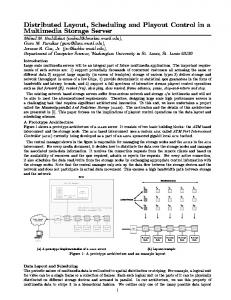
2.1 Design and Optimization System-level design of embedded systems is typically composed of several steps, as illustrated in Figure 2.1. In the “System Specification” step, an abstract system model is developed. In our application model, functional blocks are represented as processes and communication data is encapsulated into messages. Time constraints are imposed in form of deadlines assigned to the whole application, to individual processes or to groups of dependent processes.
11
C HAPTER 2
The hardware architecture is selected in the “Architecture Selection” step. The architecture for automotive applications that we consider in this thesis consists of a set of computation nodes connected to a bus. The computation nodes are heterogeneous and have different performance characteristics and reliability properties. They also have different costs, depending on their performance, reliability, power consumption and other parameters. Designers should choose an architecture with a good price-to-quality ratio within the imposed cost constraints. In the “Mapping & Hardware/Software Partitioning” step, mapping of application processes on computation nodes has to be decided such that the performance of the system is maximized and given design constraints are satisfied [Pra94, Pop04b, Pop04c, Pop04a]. These can include memory constraints, power constraints, as well as security- and safety-related constraints. Some processes can be implemented in hardware using ASICs or FPGAs. The decision on whether to implement processes in hardware is taken during hardware/software partitioning of the application [Cho95, Ele97, Ern93, Bol97, Dav99, Axe96, Mir05].
System Specification Architecture Selection Mapping & Hardware/ Software Partitioning Scheduling Back-end Synthesis Figure 2.1: Generic Design Flow 12
Feedback loops
B ACKGROUND
AND
R ELATED W ORK
After mapping and partitioning, the execution order and start times of processes are considered in the “Scheduling” step. Scheduling can be either static or dynamic. In the case of dynamic scheduling, start times are determined online based on priorities assigned to the processes [Liu73, Tin94, Aud95]. In static cyclic scheduling [Kop97, Jia00], start times of processes and sending times of messages are pre-defined off-line and stored in form of schedule tables. Researchers have developed several algorithms to efficiently produce static schedules offline. Many of these algorithms are based on list scheduling heuristics [Cof72, Deo98, Jor97, Kwo96]. However, off-line static cyclic scheduling lacks flexibility and, unless extended with adaptive functionality, cannot handle overloads or efficiently provide fault recovery [Dim01, Kan03a]. In this thesis we overcome the limitations of static cyclic scheduling by employing quasi-static scheduling techniques, which will be used to design fault-tolerant systems and can provide the flexibility needed to efficiently handle soft real-time processes [Cor04b]. Quasi-static scheduling algorithms produce a tree of schedules, between which the scheduler switches at runtime based on the conditions (such as fault occurrences or process finishing times) calculated online, during the runtime of the application. If, according to the resulted schedule, deadlines are not satisfied or the desired quality-of-service level is not achieved, then either mapping or partitioning should be changed (see the feedback line in Figure 2.1). If no acceptable solution in terms of quality, costs or deadlines can be found by optimizing process mapping and/or the schedule, then the hardware architecture needs to be modified and the optimization will be performed again. After a desirable implementation has been found, the backend system synthesis of a prototype will be performed for both hardware and software (shown as the last step in the design flow).
13
C HAPTER 2
If the prototype does not meet requirements, then either the design or specification will have to be changed. However, redesign of the prototype has to be avoided as much as possible by efficient design optimization in the early design stages, in order to reduce design costs.
2.2 Fault Tolerance Techniques In this section, we present first several error-detection techniques that can be applied against transient faults. Then, we discuss software-based fault tolerance techniques such as reexecution, rollback recovery with checkpointing, and software replication, and introduce hardening techniques. 2.2.1 ERROR DETECTION TECHNIQUES In order to achieve fault tolerance, a first requirement is that transient faults have to be detected. Researchers have proposed several error-detection techniques against transient faults, including watchdogs, assertions, signatures, duplication, and memory protection codes. Signatures. Signatures [Nah02a, Jie92, Mir95, Sci98, Nic04] are among the most powerful error detection techniques. In this technique, a set of logic operations can be assigned with precomputed “check symbols” (or “checksum”) that indicate whether a fault has happened during those logic operations. Signatures can be implemented either in hardware, as a parallel test unit, or in software. Both hardware and software signatures can be systematically applied without knowledge of implementation details. Watchdogs. In the case of watchdogs [Ben03, Mah88, Mir95], program flow or transmitted data is periodically checked for the presence of faults. The simplest watchdog schema, watchdog timer, monitors the execution time of processes, whether it exceeds a certain limit [Mir95]. Another approach is to incorpo14
B ACKGROUND
AND
R ELATED W ORK
rate simplified signatures into a watchdog. For example, it is possible to calculate a general “checksum” that indicates correct behaviour of a computation node [Sos94]. Then, the watchdog will periodically test the computation node with that checksum. Watchdogs can be implemented either in hardware as a separate processor [Ben03, Mah88] or in software as a special test program. Assertions. Assertions [Gol03, Hil00, Pet05] are an application-level error-detection technique, where logical test statements indicate erroneous program behaviour (for example, with an “if ” statement: if not then ). The logical statements can be either directly inserted into the program or can be implemented in an external test mechanism. In contrast to watchdogs, assertions are purely application-specific and require extensive knowledge of the application details. However, assertions are able to provide much higher error coverage than watchdogs. Duplication. If the results produced by duplicated entities are different, then this indicates the presence of a fault. Examples of duplicated entities are duplicated instructions [Nah02b], functions [Gom06], procedure calls [Nah02c], and whole processes. Duplication is usually applied on top of other error detection techniques to increase error coverage. Memory protection codes. Memory units, which store program code or data, can be protected with error detection and correction codes (EDACs) [Shi00, Pen95]. An EDAC code separately protects each memory block to avoid propagation of faults. A common schema is “single-error-correcting, double-error-detecting” (SEC-DED) [Pen95] that can correct one fault and detect two faults simultaneously in each protected memory block. Other error-detection techniques. There are several other error-detections techniques, for example, transistor-level current monitoring [Tsi01] or the widely-used parity-bit check. Error coverage of error-detection techniques has to be as high as possible. Therefore, several error-detection techniques are 15
C HAPTER 2
often applied together. For example, hardware signatures can be combined with transistor-level current monitoring, memory protection codes and watchdogs. In addition, the application can contain assertions and duplicated procedure calls. Error-detection techniques introduce an error-detection overhead, which is the time needed for detecting faults. The errordetection overhead can vary a lot with the error-detection technique used. In our work, unless other specified, we account the error-detection overhead in the worst-case execution time of processes. 2.2.2 RE-EXECUTION In software, after a transient fault is detected, a fault tolerance mechanism has to be invoked to handle this fault. The simplest fault tolerance technique to recover from fault occurrences is reexecution [Kan03a]. With re-execution, a process is executed again if affected by faults. The time needed for the detection of faults is accounted for by error-detection overhead. When a process is re-executed after a fault has been detected, the system restores all initial inputs of that process. The process re-execution operation requires some time for this, which is captured by the recovery overhead. In order to be restored, the initial inputs to a process have to be stored before the process is executed for first time. For the sake of simplicity, however, we will ignore this particular overhead, except for the discussion of rollback recovery with checkpointing in Section 2.2.3, Section 3.2, and Chapter 6.1 The error detection
1. The overhead due to saving process inputs does not influence the design decisions during mapping and policy assignment optimization when re-execution is used. However, we will consider this overhead in rollback recovery with checkpointing as part of the checkpointing overhead during the discussion about checkpoint optimization in Chapter 6.
16
B ACKGROUND
AND
R ELATED W ORK
α =10 ms
a)
P1
b)
P1/1
P1/2 μ = 10 ms
C1 = 60 ms
Figure 2.2: Re-execution
and recovery overheads will be denoted throughout this work with α and μ, respectively. Figure 2.2 shows the re-execution of process P1 in the presence of a single fault. As illustrated in Figure 2.2a, the process has the worst-case execution time of 60 ms, which includes the error-detection overhead α of 10 ms. In Figure 2.2b process P1 experiences a fault and is re-executed. We will denote the j-th execution of process Pi as Pi/j. Accordingly, the first execution of process P1 is denoted as P1/1 and its re-execution P1/2. The recovery overhead μ = 10 ms is depicted as a light grey rectangle in Figure 2.2. 2.2.3 ROLLBACK RECOVERY WITH CHECKPOINTING The time needed for re-execution can be reduced with more complex fault tolerance techniques such as rollback recovery with checkpointing [Pun97, Bar08, Yin03, Yin06, Ora94, Aya08, Kri93]. The main principle of this technique is to restore the last non-faulty state of the failing process. The last non-faulty state, or checkpoint, has to be saved in advance in the static memory and will be restored if the process fails. The part of the process between two checkpoints or between a checkpoint and the end of the process is called an execution segment.1
1. Note that re-execution can be considered as rollback recovery with a single checkpoint, where this checkpoint is the initial process state and the execution segment is the whole process.
17
C HAPTER 2
There are several approaches to distribute checkpoints. One approach is to insert checkpoints in the places where saving of process states is the fastest [Ziv97]. However, this approach is application-specific and requires knowledge of application details. Another approach is to systematically insert checkpoints, for example, at equal intervals [Yin06, Pun97, Kwa01]. An example of rollback recovery with checkpointing is presented in Figure 2.3. We consider processes P1 with the worstcase execution time of 60 ms and error-detection overhead α of 10 ms, as depicted in Figure 2.3a. In Figure 2.3b, two checkpoints are inserted at equal intervals. The first checkpoint is the initial state of process P1. The second checkpoint, placed in the middle of process execution, is for storing an intermediate process state. Thus, process P1 is composed of two execution segments. We will name the k-th execution segment of process Pi as P ik . Accordingly, the first execution segment of process P1 is P 11 and its second segment is P 12 . Saving process states, including saving initial inputs, at checkpoints, takes a certain amount of time that is considered in the checkpointing overhead χ, depicted as a black rectangle. In Figure 2.3c, a fault affects the second execution segment P 12 of process P1. This faulty segment is executed again starting from the second checkpoint. Note that the error-detection overhead α is not considered in the last recovery in the context of rollback recovery with checkpointing because, in this example, we assume that a maximum of one fault can happen. We will denote the j-th execution of k-th execution segment of k . Accordingly, the first execution of execution process Pi as P i/j α =10 ms
a)
P1 C1 = 60 ms
b)
1
P1
2
P1
χ = 5 ms
c)
1
P1
2
P1/1 μ = 10 ms
Figure 2.3: Rollback Recovery with Checkpointing 18
2
P1/2
B ACKGROUND
AND
R ELATED W ORK
2 segment P 12 has the name P 1/1 and its second execution is 2 . Note that we will not use the index j if we only named P 1/2 have one execution of a segment or a process, as, for example, P1’s first execution segment P 11 in Figure 2.3c. When recovering, similar to re-execution, we consider a recovery overhead μ, which includes the time needed to restore checkpoints. In Figure 2.3c, the recovery overhead μ, depicted with a light gray rectangle, is 10 ms for process P1. The fact that only a part of a process has to be restarted for tolerating faults, not the whole process, can considerably reduce the time overhead of rollback recovery with checkpointing compared to re-execution.
2.2.4 ACTIVE AND PASSIVE REPLICATION The disadvantage of rollback recovery techniques, such as reexecution1 and rollback recovery with checkpointing, is that they are unable to explore spare capacity of available computation nodes and, by this, to possibly reduce the schedule length. If the process experiences a fault, then it has to recover on the same computation node. In contrast to rollback recovery technique, active and passive replication techniques can utilize available spare capacity of other computation nodes. Moreover, active replication provides the possibility of spatial redundancy, e.g. the ability to execute process replicas in parallel on different computation nodes. In the case of active replication [Xie04], all replicas of processes are executed independently of fault occurrences. In the case of passive replication, also known as primary-backup [Ahn97, Sze05], on the other hand, replicas are executed only if faults occur. In Figure 2.4 we illustrate primary-backup and active replication. We consider process P1 with the worst-case execution time of 60 ms and error-detection overhead α of 10 ms, 1. Sometimes referred as rollback recovery with a single checkpoint.
19
C HAPTER 2
N1
P1(1)
N2
P1(2)
N1
P1(1)
b1) α =10 ms
a)
N1
P1(1)
c 1) N2
P1 C1 = 60 ms
b2)
c 2) N2
P1(2)
N1 N2
P1(1) P1(2)
Figure 2.4: Active Replication (b) and Primary-Backup (c) see Figure 2.4a. Process P1 will be replicated on two computation nodes N1 and N2, which is enough to tolerate a single fault. We will name the j-th replica of process Pi as Pi(j). Note that, for the sake of uniformity, we will consider the original process as the first replica. Hence, the replica of process P1 is named P1(2) and process P1 itself is named as P1(1). In the case of active replication, illustrated in Figure 2.4b, replicas P1(1) and P1(2) are executed in parallel, which, in this case, improves system performance. However, active replication occupies more resources compared to primary-backup because P1(1) and P1(2) have to run even if there is no fault, as shown in Figure 2.4b1. In the case of primary-backup, illustrated in Figure 2.4c, the “backup” replica P1(2) is activated only if a fault occurs in P1(1). However, if faults occur, primary-backup takes more time to complete compared to active replication as shown in Figure 2.4c2, compared to Figure 2.4b2. To improve performance, primary-backup can be enhanced with checkpointing as discussed, for example, in [Sze05] so that only a part of the replica is executed in the case of faults. In our work, we are mostly interested in active replication. This type of replication provides the possibility of spatial redundancy, which is lacking in rollback recovery. 20
B ACKGROUND
AND
R ELATED W ORK
2.2.5 HARDENING Transient faults can also be addressed with hardening techniques, i.e., improving the hardware architecture to reduce the transient fault rate. Researchers have proposed a variety of hardware hardening techniques. Zhang et al. [Zha06] have proposed an approach to hardening of flip-flops, resulting in a small area overhead and significant reduction in the transient fault rate. Mohanram and Touba [Moh03] have studied hardening of combinatorial circuits. Zhou et al. [Zho08] have proposed a “filtering technique” for hardening of combinatorial circuits. Zhou and Mohanram [Zho06] have studied the problem of gate resizing as a technique to reduce the transient fault rate. Garg et al. [Gar06] have connected diodes to the duplicated gates to implement an efficient and fast voting mechanism. Finally, a hardening approach to be applied in early design stages has been presented in [Hay07], which is based on the transient fault detection probability analysis. Nevertheless, hardening comes with a significant overhead in terms of cost and speed [Pat08, Tro06]. The main factors which affect the cost are the increased silicon area, additional design effort, lower production quantities, excessive power consumption, and protection mechanisms against radiation, such as shields. Hardened circuits are also significantly slower than the regular ones. Manufacturers of hardened circuits are often forced to use technologies few generations back [Pat08, Tro06]. Hardening also enlarges the critical path of the circuit, because of a voting mechanism [Gar06] and increased silicon area. To reduce the probability of faults, the designer can choose to use a hardened, i.e., a more reliable, version of the computation node. Such a hardened version will be called an h-version. Thus, each node Nj is available in several versions, with different hardening levels, denoted with h. We denote Njh the h-version of node Nj, and with C jh the cost associated with Njh . In Figure 2.5 we consider one process, P1, and one computation node, N1, with 21
C HAPTER 2
1
a) N1
2
b) N1 c)
3 N1
N1
P1 P1
P1 P1
Cost
h=2
h=1
N1 t
p
80
4· 10-2
t
p
100 4· 10-4
10
20
h=3 t
p
160
4· 10-6 40
Figure 2.5: Hardening
three h-versions, N11 without hardening and N12 and N13 progressively more hardened. The execution times (t) and failure probabilities (p) for the process on different h-versions of node N1 are shown in the table. The corresponding costs are also associated with these versions (given at the bottom of the table). For example, with the h-version N12 , the failure probability is reduced by two orders of magnitude, compared to the first version N11 . However, using N12 will cost twice as much as the solution with less hardening. Moreover, with more hardening, due to performance degradation, the execution time on N13 is twice as much as on the first version N11 .
2.3 Transparency A common systematic approach for debugging embedded software is to insert observation points into software and hardware [Vra97, Tri05, Sav97] for observing the system behaviour under various circumstances. The observation points are usually inserted by an expert, or can be automatically injected based on statistical methods [Bou04]. In order to efficiently trace design errors, the results produced with the observation points have to be easily monitored, even in the recovery scenarios against transient faults. Tolerating transient faults leads to many execution scenarios, which are dynamically adjusted in the case of fault occurrences. 22
B ACKGROUND
AND
R ELATED W ORK
The number of execution scenarios grows exponentially with the number of processes and the number of tolerated transient faults. In order to debug, test, or verify the system, all its execution scenarios have to be taken into account. Therefore, monitoring observation points for all these scenarios is often infeasible and debugging, verification and testing become very difficult. The overall number of possible recovery scenarios can be considerably reduced by restricting the system behaviour, in particular, by introducing transparency requirements or, simply, transparency. A transparent recovery scheme has been proposed in [Kan03a], where recovering from a transient fault on one computation node does not affect the schedule of any other node. In general, transparent recovery has the advantage of increased debugability, where the occurrence of faults in a certain process does not affect the execution of other processes, which reduces the total number of execution scenarios. At the same time, with increased transparency, the amount of memory needed to store the schedules decreases. However, transparent recovery increases the worst-case delay of processes, potentially reducing the overall performance of the embedded system. Thus, efficient design optimization techniques are even more important in order to meet time and cost constraints in the context of faulttolerant embedded systems with transparency requirements. To our knowledge, most of the design strategies proposed so far [Yin03, Yin06, Xie04, Pin08, Sri95, Mel04, Aya08, Bar08, Aid05] have not explicitly addressed the transparency requirements for fault tolerance. If at all addressed, these requirements have been applied, at a very coarse-grained level, to a whole computation node, as in the case of the original transparent reexecution proposed in [Kan03a].
23
C HAPTER 2
2.4 Design Optimization with Fault Tolerance Fault-tolerant embedded systems have to be optimized in order to meet time, quality-of-service, and cost constraints. Researchers have shown that schedulability of an application can be guaranteed for pre-emptive online scheduling under the presence of a single transient fault [Ber94, Bur96, Han03]. Liberato et al. [Lib00] have proposed an approach for design optimization of monoprocessor systems in the presence of multiple transient faults and in the context of pre-emptive earliestdeadline-first (EDF) scheduling. Ying Zhang and Chakrabarty [Yin03] have proposed a checkpointing optimization approach for online fixed-priority scheduling to tolerate k faults in periodic real-time tasks during a hyperperiod. The application is run on a monoprocessor system and only rollback recovery with checkpointing is considered as a fault tolerance technique. Hardware/software co-synthesis with fault tolerance has been addressed in [Sri95] in the context of event-driven scheduling. Hardware and software architectures have been synthesized simultaneously, providing a specified level of fault tolerance and meeting the performance constraints, while minimizing the system costs. Safety-critical processes are re-executed in order to tolerate transient fault occurrences. This approach, in principle, also addresses the problem of tolerating multiple transient faults, but does not consider static cyclic scheduling. Design optimization is limited to only hardware/software co-design, where some of the software functionality is migrated to ASICs for improving performance. Both hard and soft real-time constraints are considered in this work. However, value-based scheduling optimization is not performed, assuming unchanged fixed priorities of process executions in all hardware/software co-design solutions. Xie et al. [Xie04] have proposed a technique to decide how replicas can be selectively inserted into the application, based on process criticality. Introducing redundant processes into a pre24
B ACKGROUND
AND
R ELATED W ORK
designed schedule has been used in [Con05] in order to improve error detection. Both approaches only consider one single fault. Szentivanyi et al. [Sze05] have proposed a checkpoint optimization approach in the context of servers running high-availability applications, employing primary-backup replication strategy. The queuing theory has been used to mathematically model system behaviour in the context of requests arriving to the servers, and in order to optimize system availability in the presence of faults. However, as the authors in [Sze05] have re-called, their approach is not suitable for hard real-time applications, as the ones discussed in this thesis. Moreover, fault tolerance policy assignment, mapping and scheduling with fault tolerance are not addressed in [Sze05]. Ayav et al. [Aya08] have achieved fault tolerance for real-time programs with automatic transformations, where recovery with checkpointing is used to tolerate one single fault at a time. Shye et al. [Shy07] have developed a process-level redundancy approach against multiple transient faults with active replication on multi-core processors in general-purpose computing systems. Design optimization and scheduling are not addressed in [Shy07], assuming a given fault tolerance and execution setup. Wattanapongsakorn and Levitan [Wat04] have optimized reliability for embedded systems, both for hardware and software, taking costs aspects into account. However, their technique is limited to only software or hardware permanent faults of a component, i.e., transient faults are not addressed. Traditional hardware replication and N-version programming are used as fault tolerance techniques. A simulated annealing-based algorithm has been developed to provide design optimization of the reliability against permanent faults with reduced hardware and software costs of the fault tolerance. However, neither mapping optimization nor scheduling have been addressed in [Wat04]. Aidemark et al. [Aid05] have developed a framework for nodelevel fault tolerance in distributed real-time systems. Systematic and application-specific error detection mechanisms with 25
C HAPTER 2
recovery have been used to ensure fail-silent behaviour of computation nodes in the presence of transient faults. Although a fixed priority scheduling with reserved recovery slacks is assumed to be employed, design optimization and scheduling with fault tolerance are not addressed in [Aid05]. Power-related optimization issues of fault-tolerant embedded systems have been studied in [Yin06, Jia05, Zhu05, Mel04, Wei06, Pop07]. Ying Zhang et al. [Yin04, Yin06] have studied fault tolerance and dynamic power management in the context of message-passing distributed systems. The number of checkpoints has been optimized in order to improve power consumption and meet timing constraints of the system without, however, performing fault tolerance-aware optimization of mapping and scheduling. Fault tolerance has been applied on top of a pre-designed system, whose process mapping and scheduling ignore the fault tolerance issue. Jian-Jun Han and Qing-Hua Li [Jia05] have proposed a scheduling optimization algorithm for reducing power consumption in the context of online least-execution-time-first scheduling. Dakai Zhu et al. [Zhu05] have studied sequential and parallel recovery schemes on a set of distributed servers, which tolerate arbitrary faults affecting aperiodic tasks/requests. They use very different application model and neither consider hard deadlines nor optimize scheduling or mapping of processes. Melhem et al. [Mel04] have considered checkpointing for rollback recovery in the context of online earliest-deadline-first (EDF) scheduling on a monoprocessor embedded system. They have proposed two checkpointing policies for reducing power consumption, where the number of checkpoints can be analytically determined in the given context of EDF scheduling. Wei et al. [Wei06] have proposed an online scheduling algorithm for power consumption minimization in the context of hard real-time monoprocessor systems. Pop et al. [Pop07] have studied reliability and power consumption of distributed embedded systems. Mapping has been considered as given to the problem and only scheduling has been optimized. A 26
B ACKGROUND
AND
R ELATED W ORK
scheduling technique, based on our scheduling approach presented in Chapter 4 of this thesis, has been proposed to provide a schedulable solution, which satisfies the reliability against the given number of transient faults with the lowest-possible power consumption. Kandasamy et al. [Kan03a] have proposed constructive mapping and scheduling algorithms for transparent re-execution on multiprocessor systems. The work has been later extended with fault-tolerant transmission of messages on a time-division multiple access bus [Kan03b]. Both papers consider only one fault per computation node, and only process re-execution is used. Very few research work is devoted to general design optimization in the context of fault tolerance. For example, Pinello et al. [Pin04, Pin08] have proposed a simple heuristic for combining several static schedules in order to mask fault patterns. Passive replication has been used in [Alo01] to handle a single failure in multiprocessor systems so that timing constraints are satisfied. Multiple failures have been addressed with active replication in [Gir03] in order to guarantee a required level of fault tolerance and satisfy time constraints. None of these previous work, however, has considered optimal assignment of fault tolerance policies, nor has addressed multiple transient faults in the context of static cyclic scheduling. Regarding hardware, a variety of hardening optimization techniques against transient faults have been developed, which optimize hardware cost and area overhead with respect to hardware reliability [Zha06, Moh03, Zho06, Zho08, Hay07, Gar06]. However, these techniques target optimization of hardware alone and do not consider embedded applications, which will be executed on this hardware and their fault recovery capabilities. Thus, hardening may either lead to unnecessary overdesign of hardware or to its insufficient reliability since hardware designers will use unrealistic assumptions about the software and the system as a whole. To overcome this limitation, hardware hard27
C HAPTER 2
ening levels should be optimized in a more global system context, taking into account properties of the application and system requirements. Regarding soft real-time systems, researchers have shown how faults can be tolerated with active replication while maximizing the quality level of the system [Mel00]. During runtime, the resource manager allocates available system resource for each arrived process such that the overall quality of the system is not compromised while degree of the fault tolerance is maintained. An online greedy resource allocation algorithm has been proposed, which incrementally chooses waiting process replicas and allocate them to the least loaded processors. In [Ayd00] faults are tolerated while maximizing the reward in the context of online scheduling and an imprecise computation model, where processes are composed of mandatory and optional parts. Monoprocessor architecture is considered and the fault tolerance is provided with online recovering of the task parts. In [Fux95] the trade-off between performance and fault tolerance, based on active replication, is considered in the context of online scheduling. This, however, incurs a large overhead during runtime which seriously affects the quality of the results. None of the above approaches considers value-based scheduling optimization in the context of static cyclic scheduling. In general, the considered value-based optimization is either very limited and based on costly active replication [Mel00, Fux95] or restricted to monoprocessor systems with online scheduling [Ayd00]. Hard and soft real-time systems have been traditionally scheduled using very different techniques [Kop97]. However, many applications have both components with hard and soft timing constraints [But99]. Therefore, researchers have recently proposed techniques for addressing mixed hard and soft realtime systems [But99, Dav93, Cor04b]. Particularly, Cortes et al. [Cor04b] have developed a design approach for multiprocessor embedded systems composed of soft and hard processes. None of 28
B ACKGROUND
AND
R ELATED W ORK
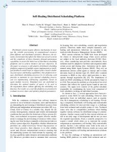
the above mentioned work on mixed soft and hard real-time systems, however, addresses fault tolerance aspects. Hereafter we present the summary of limitations of previous research work, which we address in this thesis: • design optimization of embedded systems with fault tolerance is usually restricted to a single aspect, as, for example, process mapping is not considered together with fault tolerance issues; • fault tolerance policy assignment, e.g., deciding which fault tolerance technique or combination of techniques to apply to a certain process, is not considered; • multiple faults are not addressed in the context of static cyclic scheduling; • transparency, if at all addressed, is restricted to a whole computation node and is not flexible; • fault tolerance aspects are not considered for mixed soft and hard real-time systems, i.e., the value-based optimization in the context of fault-tolerant mixed soft/hard embedded systems is not addressed; • reliability of hardware is usually addressed alone, without considering software-level fault tolerance, which may lead to unnecessarily expensive solutions. 2.4.1 DESIGN FLOW WITH FAULT TOLERANCE TECHNIQUES In Figure 2.6 we enhance the generic design flow presented in Figure 2.1, with the consideration of fault tolerance techniques. In the “System Specification and Architecture Selection” stage, designers specify, besides other functional and non-functional properties, timing constraints, for example, deadlines, and select a certain fault-tolerant architecture. They also set the maximum number k of transient faults in the application period T, which must be tolerated in software for the selected architecture. Designers can introduce transparency requirements in order to improve the debugability and testability on the selected archi29
C HAPTER 2
System Specification and Architecture Selection
tecture (step A in Figure 2.6). Based on the number k of transient faults and the transparency requirements, design
P2
m4
P1
m2
m3
m5
P3
U1(t)
Period T
m1 P4
k faults
Application
U2(t)
A P2
m4
P1
m2
m3
Fault-Tolerant Hardware Architecture
m5 P3
P4
d4
d3
m1
Timing Constraints
Transparency
Design Optimization and Scheduling
B
G
P1 : Replication P2 : Re-execution + Replication P3 : Re-execution + Replication P4 : Re-execution
C
Fault Tolerance Policy Assignment
D
F N 1 true FP1 P1 P2 m1 m2 m3
0
Mapping
FP FP ∧ FP FP ∧ FP FP ∧ FP ∧ FP 1 1 1 1 2 1 1 1
35 30 31 105
70 100 100 105 120
65 66 105
Schedule Tables
90
E
120
Fault-Tolerant Process Graph (FTPG)
Mapped and Scheduled Application
Figure 2.6: Design Flow with Fault Tolerance 30
B ACKGROUND
AND
R ELATED W ORK
optimization and scheduling are performed in the “Design Optimization and Scheduling” stage.1 In the “Fault Tolerance Policy Assignment” step in Figure 2.6, processes are assigned with fault tolerance techniques against transient faults. For example, some processes can be assigned with recovery (re-execution), some with active replication, and some with a combination of recovery and replication. In the context of rollback recovery, we also determine the adequate number of checkpoints. The policy assignment is passed over to the “Mapping” step (C), where a mapping algorithm optimizes the placement of application processes and replicas on the computation nodes. After that, the application is translated in step D into an intermediate representation, a “Fault-Tolerant Process Graph”, which is used in the scheduling step. The fault-tolerant process graph (FTPG) representation captures the transparency requirements and all possible combinations of fault occurrences. Considering the mapping solution and the FTPG, a fault-tolerant schedule is synthesized (E) as a set of “Schedule Tables”, which are captured in a schedule tree. The generated schedules have to meet hard deadlines even in the presence of k faults in the context of limited amount of resources. If the application is unschedulable, the designer has to change the policy assignment and/or mapping (F). If a valid solution cannot be obtained after an extensive iterative mapping and policy assignment optimization, then the system specification and requirements, for example, transparency requirements or timing constraints, have to be adjusted or the fault-tolerant hardware architecture has to be modified (G).
1. Our design optimization and scheduling strategies, presented in Part II and Part III of the thesis, in general, follow this design flow with the maximum number k of transient faults provided by the designer. In Part IV, however, the number k of transient faults to be considered is calculated based on our system failure probability analysis.
31
Chapter 3 Preliminaries
I N THIS CHAPTER we introduce our application and quality-ofservice (utility) models, hardware architecture, and our fault model. We also present our approach to process recovery in the context of static cyclic scheduling.
3.1 System Model In this section we present details regarding our application models, including a quality-of-service model, and system architecture. 3.1.1 HARD REAL-TIME APPLICATIONS In Part II and Part IV of this thesis, we will consider hard realtime applications. We model a hard real-time application A as a set of directed, acyclic graphs merged into a single hypergraph G(V, E). Each node Pi ∈ V represents one process. An edge eij ∈ E from Pi to Pj indicates that the output of Pi is the input of Pj. Processes are non-preemptable and cannot be interrupted by other processes. Processes send their output values encapsu-
33
C HAPTER 3
A1:G1
m1
P1 m 2
d 2 = 200 ms P2
d1 = 160 ms
P3 m4 m5
m3 d 4 = 240 ms P4
P5
D = 240 ms
d 3 = 200 ms
P1 P2 P3 P4 P5
N1 20 40 60 40 40
N2
d 5 = 240 ms
(b)
(a) WCET
N1
WCTT
N2 30 60 X 60 60
m1 m2 m3 m4 m5
10 5 10 10 5
T = 250 ms k=1 μ = 5 ms (e)
(d)
(c) Figure 3.1: Hard Real-Time Application lated in messages, when completed. All required inputs have to arrive before activation of the process. Figure 3.1a shows a simple application A1 represented as a graph G1 composed of five nodes (processes P1 to P5) connected with five edges (messages m1 to m5). In a hard real-time application, violation of a deadline is not allowed. We capture time constraints with hard deadlines di ∈ D, associated to processes in the application A. In Figure 3.1a, all processes have to complete before their deadlines di, for example, process P1 has to complete before d1 = 160 ms and process P5 before d5 = 240 ms. In this thesis, we will often represent the hard deadlines in form of a global cumulative deadline D1. 1. An individual hard deadline di of a process Pi is modelled as a dummy node inserted into the application graph with the execution time Cdummy = D − di, which, however, is not allocated to any resource [Pop03].
34
P RELIMINARIES
3.1.2 MIXED SOFT AND HARD REAL-TIME APPLICATIONS In Part III of this thesis, we will consider mixed soft and hard real-time applications, and will extend our hard real-time approaches to deal also with soft timing constraints. Similar to the hard real-time application model, we model a mixed application A as a set of directed, acyclic graphs merged into a single hypergraph G(V, E). Each node Pi ∈ V represents one process. An edge eij ∈ E from Pi to Pj indicates that the output of Pi is the input of Pj. The mixed application consists of hard and soft real-time processes. Hard processes are mandatory to execute and have to meet their hard deadlines. Soft processes, as opposed to hard ones, can complete after their deadlines. Completion time of a soft process is associated with a value (utility) function that characterizes its contribution to the quality-ofservice of the application. Violation of a soft timing constraint is not as critical as violation of a hard deadline. However, it may lead to application quality deterioration, as will be discussed in Section 3.1.6. Moreover, a soft process may not start at all, e.g. may be dropped, to let a hard or a more important soft process execute instead. In Figure 3.2 we have an application A2 consisting of the process graph G2 with four processes, P1 to P4. The hard part A2:G2
P1
m1 m5 P2
M(Pi) BCET N1 30 N1 50 N2 50 N2 30
d1 = 250ms m2
P1 P2 P3 P4
P3 m4
m3 P4
d4 = 380ms
k=2 μ = 5 ms
AET WCET 50 70 60 100 75 120 60 80
T=400ms m2 : m3 : 10 ms
N1
N2 m5 : 5 ms
Figure 3.2: Mixed Soft and Hard Real-Time Application 35
C HAPTER 3
consists of hard processes P1 and P4 and hard message m5. Process P1 has deadline d1 = 250 ms and process P4 has deadline d4 = 380 ms. The soft part consists of soft process P2 with soft messages m1 and m3, and soft process P3 with soft messages m2 and m4, respectively. A soft process can complete after its deadline and the utility functions are associated to soft processes, as will be discussed in Section 3.1.6. The decision which soft process to execute and when should eventually increase the overall quality-of-service of the application without, however, violation of hard deadlines in the hard part. 3.1.3 BASIC SYSTEM ARCHITECTURE The real-time application is assumed to run on a hardware architecture, which is composed of a set of computation nodes connected to a communication infrastructure. Each node consists of a memory subsystem, a communication controller, and a central processing unit (CPU). For example, an architecture composed of two computation nodes (N1 and N2) connected to a bus is shown in Figure 3.1b. The application processes have to be mapped on the computation nodes. The mapping of an application process is determined by a function M: V → N, where N is the set of nodes in the architecture. For a process Pi ∈ V , its mapping M(Pi) is the node Nj to which Pi is assigned for execution. We consider that the mapping of the application is not fixed and has to be determined as a part of the design optimization. For real-time applications, we know, first of all, a worst-case execution time (WCET), tijw. Although finding the WCET of a process is not trivial, there exists an extensive portfolio of methods that can provide designers with safe worst-case execution time estimations [Erm05, Sun95, Hea02, Jon05, Gus05, Lin00, Col03, Her00, Wil08]. Figure 3.1c shows the worst-case execution times of processes of the application A1 depicted in Figure 3.1a. For example, process P2 has the worst-case execu36
P RELIMINARIES
tion time of 40 ms if mapped on computation node N1 and 60 ms if mapped on computation node N2. By “X” we show mapping restrictions. For example, process P3 cannot be mapped on computation node N2. Besides a worst-case execution time (WCET), tijw, we also know for each process Pi, when mapped on node Nj, a best-case execution time (BCET), tijb, and an expected (average) execution time (AET), tije, given by w
e = t ij
t ij
∫tb tEij ( t ) dt ij
for an arbitrary continuous execution time probability distribution Eij(t) of process Pi on computation node Nj. In Figure 3.2, with a mixed application A2, the execution times for processes P1, P2, P3 and P4 and transmission times of messages are shown in the table, as if processes P1 and P2 are mapped on computation node N1, and P3 and P4 on N2. Processes mapped on different computation nodes communicate by messages sent over the bus. We consider that the worstcase sizes of messages are given, which can be implicitly translated into the worst-case transmission times on the bus. For example, Figure 3.1d shows the worst-case transmission times of messages implicitly derived from the message worst-case sizes, in the case the messages are transmitted over the bus. If processes are mapped on the same node, the message transmission time between them is accounted for in the worst-case execution time of the sending process. 3.1.4 FAULT TOLERANCE REQUIREMENTS In our system model, we consider that at most k transient faults may occur during a hyperperiod T of the application running on the given architecture. The application software has to tolerate these transient faults by fault tolerance techniques such as rollback recovery or active replication. For example, application 37
C HAPTER 3
A1 has to tolerate k = 1 transient faults in the hyperperiod T = 250 ms, as depicted in Figure 3.1e; application A2 in Figure 3.2 has to tolerate k = 2 transient faults in its hyperperiod T = 400 ms. Overheads related to fault tolerance are also part of our system model. When recovering from faults, we explicitly consider a recovery overhead μ, which includes the time needed to restore a process state and restart the process (or a part of the process). For example, recovery overhead μ is 5 ms for both applications A1 and A2, as depicted in Figure 3.1e and Figure 3.2, respectively. Checkpointing overhead χ and error detection overhead α are also considered, as discussed in Section 2.2. However, since they do not influence design optimization and scheduling decisions we will not explicitly model them except the discussion on checkpoint optimization in Section 3.2 and Chapter 6. 3.1.5 ADAPTIVE STATIC CYCLIC SCHEDULING In this thesis, we will consider a static cyclic scheduling based approach. With static cyclic scheduling both communications and processes are scheduled such that start times are determined off-line using scheduling heuristics. These start and sending times are stored in form of schedule tables on each computation node. Then, the runtime scheduler of a computation node will use the schedule table of that node in order to invoke processes and send messages on the bus. In Figure 3.3b we depict a static schedule for the application and the hardware architecture presented in Figure 3.1. Processes P1, P3 and P5 are mapped on computation node N1 (grey circles), while processes P2 and P4 are mapped on N2 (white circles). The schedule table of the computation node N1 contains start times of processes P1, P3 and P5, which are 0, 20, and 100 ms, respectively, plus sending time of message m1, which is 20 ms. The schedule table of N2 contains start times of P2 and P4, 38
P RELIMINARIES
A1:G1
P1 m 1 P2 P4
m3 P5
(a)
N1 P1
P3
N2
P3 m2
d1
bus
P2 m1
deadline D = 240 d3 d5
P5 P4
d2
d4
m4
20 40 60 80 100 120 140 160 180 200 220
time
(b) Figure 3.3: A Static Schedule
30 and 90 ms, plus sending time of message m4, which is 90 ms. According to the static schedule, the application will complete at 150 ms, which satisfies the cumulative deadline D of 240 ms. All local deadlines of hard processes are also met. Static cyclic scheduling, which we have used to generate the schedule in Figure 3.3b, is an attractive option for safety-critical applications. It provides predictability and deterministic behaviour. However, unless extended with adaptive functionality, it cannot efficiently handle faults and overload situations [Dim01, Kan03a] by adapting to particular conditions. For example, suppose that we have to handle the maximum k = 1 transient faults for application A1 in Figure 3.1, given the option that only one single static schedule can be used. In such a schedule, each process would need to be explicitly scheduled in two copies assuming the worst-case execution times of processes, which would lead to hard deadline violations and is not efficient. In general, an application can have different execution scenarios [Ele00]. For example, some parts of the application might not be executed under certain conditions. In this case, several execution scenarios, corresponding to different conditions, have to be stored. At execution time, the runtime scheduler will choose the appropriate schedule that corresponds to the actual conditions. If the conditions change, the runtime scheduler will accordingly 39
C HAPTER 3
switch to the appropriate precalculated schedule. Such a scheduling technique is called quasi-static scheduling. Quasi-static mechanisms will be exploited in the following sections for capturing the behaviour of fault-tolerant applications. However, at first, to illustrate scheduling in the context of mixed soft and hard real-time systems, we will introduce our quality-of-service model, which is also a part of our system model. 3.1.6 QUALITY-OF-SERVICE MODEL In our mixed soft and hard real-time application model, presented in Section 3.1.2, each soft process Pi ∈ V is assigned with a utility function Ui(t), which is any non-increasing monotonic function of the completion time of a process. The overall utility of each execution scenario of the application is the sum of individual utilities produced by soft processes in this scenario. In Figure 3.4 we depict utility function U2(t) for the soft process P2 of the application A2 in Figure 3.2. According to the schedule in Figure 3.4a, P2 completes at 110 ms and its utility would be 15. For a soft process Pi we have the option to “drop”
U3(t) 0
N1
20 40
60
P1
t
N1 N2
P4
U3(t) 0
80 100 120
P2
N2
U2(t)
30 15
U2(t)
30 15
20 40
60
P1
t 80 100 120
P2 P3
P4
bus
bus m5
m3
U = U2(110) + U3(–) = 15 + 0 = 15 (a)
m5 m2
m3 *(75) =
U = U2(110) + U3 15 + 1/2 × 15 = 22.5 (b)
Figure 3.4: Utility Functions and Dropping 40
P RELIMINARIES
the process, and, thus, its utility will be 0, i.e., Ui(−) = 0. In Figure 3.4a we drop process P3 of application A2. Thus, the overall utility of the application in this case will be U = U2(110) + U3(−) = 15 + 0 = 15. We may also drop soft messages of the application alone or together with the producer process. For example, in Figure 3.4a, messages m2 is dropped. Dropping might be necessary in order to meet deadlines of hard processes, or to increase the overall system utility (e.g. by allowing other, potentially higher-value soft processes to complete). If Pi, or its re-execution, is dropped but would produce an input for another process Pj, we assume that Pj will use an input value from a previous execution cycle, i.e., a “stale” value. Thus, output values produced by processes in one execution cycle can be reused by processes in the next cycles. For example, in Figure 3.4a, process P2 will send message m3 to update an input “stale” value for process P4 in the next iteration. Reusing stale inputs, however, may lead to reduction in the utility value, i.e., utility of a process Pi would degrade to Ui*(t) = σi × Ui(t), where σi represents the stale value coefficient. σi captures the degradation of utility that occurs due to dropping of processes, re-executions and messages, and is obtained according to an application-specific rule R. In this thesis, we will consider that if a process Pi completes, but reuses stale inputs from one or more of its direct predecessors, the stale value coefficient is calculated as follows: 1+
∑
P j ∈ DP ( P i )
σj
σi = ---------------------------------------1 + DP ( P i )
where DP(Pi) is the set of Pi’s direct predecessors. If we apply the above rule to the execution scenario in Figure 3.4b, the overall utility is U=U2(110) + U3*(75) = 15 + 1/2 × 15 = 22.5. The utility of process P3 is degraded because it uses a “stale” value from process P1, i.e., P3 does not wait for input m2
41
C HAPTER 3
and its stale value coefficient σ3 = (1 + σ1) / (1 + |DP(P3)|) = (1 + 0) / (1 + 1) = 1/2.
3.2 Software-level Fault Tolerance Techniques To illustrate adaptive scheduling with fault tolerance, in Figure 3.5a we show a simple application of two processes that has to tolerate the maximum number of two transient faults, i.e., k = 2. As mentioned in Chapter 2, error detection itself introduces a certain time overhead, which is denoted with αi for a process Pi. Usually, unless otherwise specified, we account for the errordetection overhead in the worst-case execution time of processes. In the case of re-execution or rollback recovery with checkpointing, a process restoration or recovery overhead μi has to be considered for a process Pi. The recovery overhead includes the time needed to restore the process state. Rollback recovery is also characterized by a checkpointing overhead χi, which is
P1
P1
m1
P2
C1 = 60 ms
k=2
P2 C2 = 60 ms
P1 P2
χ
α
μ
10 5
5 5
5 10
(a)
(c)
P1
1
(d)
P1
0
20 40
(b) P2/1
2
P1
60
1
P2
P2/2
2
P2/1
P2/3
2
P2/2
2
P2/3
80 100 120 140 160 180 200 220 260 280 300
Figure 3.5: Fault Model and Fault Tolerance Techniques 42
P RELIMINARIES
related to the time needed to store initial and intermediate process states. We consider that the worst-case time overheads related to the particular fault tolerance techniques are given. For example, Figure 3.5b shows recovery, detection and checkpointing overheads associated with the processes of the simple application depicted in Figure 3.5a. The worst-case fault scenarios of this application in the presence of two faults, if re-execution and rollback recovery with checkpointing are applied, are shown in Figure 3.5c and Figure 3.5d, respectively. As can be seen, the overheads related to the fault tolerance techniques have a significant impact on the overall system performance. As discussed in Section 2.3, such fault tolerance techniques as re-execution and rollback recovery with checkpointing make debugging, testing, and verification potentially difficult. Transparency is one possible solution to this problem. Our approach to handling transparency is by introducing the notion of frozenness applied to a process or a message. A frozen process or a frozen message has to be scheduled at the same start time in all fault scenarios, independently of external fault occurrences1. Given an application A(V, E) we will capture the transparency using a function T: W → {Frozen, Regular}, where W is the set of all processes and messages. If T(wi) = Frozen, our scheduling algorithm will handle this transparency requirement (a) by scheduling wi, if it is a message, at the same transmission time in all alternative execution scenarios and (b) by scheduling the first execution instance of wi, if it is a process, at the same start time in all alternative execution scenarios. In a fully transparent system, all messages and processes are frozen. Systems with a node-level transparency [Kan03a] support a limited transparency setup, in which all the inter-processor messages are frozen, while all processes and all the intra-processor messages are regular. 1. External in respect to, i.e., outside, the frozen process or message.
43
C HAPTER 3
a)
P1
P1
P1
P2
no faults
b)
P1
P1
P1
P2
P2
0
20 40
60
P2
80 100 120 140 160 180 200 220 240 260 280 300 320 340 360 380 400
Figure 3.6: Transparency and Frozenness Figure 3.6 shows the non-fault scenario and the worst-case fault scenario of the application depicted in Figure 3.5a, if reexecution is applied and process P2 is frozen. Process P2 is first scheduled at 205 ms in both execution scenarios independently of external fault occurrences, e.g., faults in process P1. However, if fault occurrences are internal, i.e., within process P2, process P2 has to be re-executed as shown in Figure 3.6b. 3.2.1 RECOVERY IN THE CONTEXT OF STATIC CYCLIC SCHEDULING In the context of static cyclic scheduling, each possible execution scenario has to be captured to provide the necessary adaptability to current conditions [Ele00]. Re-execution. In case of re-execution, faults lead to different execution scenarios that correspond to a set of alternative schedules. For example, considering the same application as in Figure 3.5a, with a maximum number of faults k = 1, re-execution will require three alternative schedules as depicted in Figure 3.7a. The fault scenario in which P2 experiences a fault is shown with shaded circles. In the case of a fault in P2, the runtime scheduler switches from the non-fault schedule S0 to the schedule S2 corresponding to a fault in process P2. Similarly, in the case of multiple faults, every fault occurrence will trigger a switching to the corresponding alternative schedule. Figure 3.7b represents a tree of constructed alternative schedules for the same application of two processes, if two tran44
P RELIMINARIES
a)
b) P1
S0
P2
S1
S1
P1
S2
S0
P1
P2 S2
P2
S3
P2 S4
S5
Figure 3.7: Alternative Schedules for Re-execution sient faults can happen at maximum, i.e., k = 2. For example, as depicted with shaded circles, if process P1 experiences a fault, the runtime scheduler switches from the non-fault schedule S0 to schedule S1. Then, if process P2 experiences a fault, the runtime scheduler switches to schedule S4. Checkpointing. Figure 3.8 represents a tree of constructed alternative schedules for the same application in Figure 3.5a considering, this time, a rollback recovery schema with two checkpoints, as in Figure 3.5d. In the schedule, every execution segment P ij is considered as a “small process” that is recovered in the case of fault occurrences. Therefore, the number of alternative schedules is larger than it is in the case of pure re-execution. In Figure 3.8 we highlight the fault scenario presented in Figure 3.5d with shaded circles. The runtime scheduler switches between schedules S0, S4, and S14.
1
S0
P1
2
2
P1 S1
1
2
P1 1
2 P1
S5
S6
P2
2
S2
P1
S8
S9
2
1 P2
P2 S7
P2
1
P2
S10
P2
S3
S4
1
2
P2
P2
2
P2 S11
S12
S13
S14
Figure 3.8: Alternative Schedules for Rollback Recovery with Checkpointing 45
C HAPTER 3
Transparency. The size of the above tree of alternative schedules can be reduced by introducing transparency requirements. For example, in the case with frozen process P2 for the application in Figure 3.5a, with the corresponding schedule depicted in Figure 3.6, it is sufficient to have a single schedule to capture the application behaviour in all possible fault scenarios even in case k = 2. This can be compared to 6 schedules, depicted in Figure 3.7b, for the same application but without transparency. However, the application with 6 schedules is more flexible, which will result in the much shorter worst schedule length than in the case depicted in Figure 3.6. We will investigate this relation between transparency requirements, the schedule tree size and the schedule length in the next Chapter 4, where we present our scheduling techniques with fault tolerance.
46
PART II Hard Real-Time Systems
Chapter 4 Scheduling with Fault Tolerance Requirements
I N THIS CHAPTER we propose two scheduling techniques for fault-tolerant embedded systems in the context of hard realtime applications, namely conditional scheduling and shiftingbased scheduling. Conditional scheduling produces shorter schedules than the shifting-based scheduling, and also allows to trade-off transparency for performance. Shifting-based scheduling, however, has the advantage of low memory requirements for storing alternative schedules and fast schedule generation time. Both scheduling techniques are based on the fault-tolerant process graph (FTPG) representation. Although the proposed scheduling algorithms are applicable for a variety of fault tolerance techniques, such as replication, re-execution, and rollback recovery with checkpointing, for the sake of simplicity, in this chapter we will discuss them in the context of only re-execution.
49
C HAPTER 4
4.1 Performance/Transparency Trade-offs As defined in Section 3.2, transparency refers to providing extended observability to the embedded application. The notion of transparency has been introduced with the property of frozenness applied to processes and messages, where a frozen process or a frozen message has to be scheduled independently of external fault occurrences. Increased transparency makes a system easier to observe and debug. Moreover, since transparency reduces the number of execution scenarios, the amount of memory required to store alternative schedules, corresponding to these scenarios, is reduced. However, transparency increases the worst-case delays of processes, which can violate timing constraints of the application. These delays can be reduced by trading-off transparency for performance. In the example in Figure 4.1a, we introduce transparency properties into the application A. We let process P3 and messages m2 and m3 be frozen, i.e., T(m2) = Frozen, T(m3) = Frozen and T(P3) = Frozen. We will depict frozen processes and messages with squares, while the regular ones are represented by circles. The application has to tolerate k = 2 transient faults, and the recovery overhead μ is 5 ms. It is assumed that processes P1 and P2 are mapped on N1, and P3 and P4 are mapped on N2. Messages m1, m2 and m3, with the sending processes and receiving processes mapped on different nodes, are scheduled on the bus. Four alternative execution scenarios are illustrated in Figure 4.1b-e. The schedule in Figure 4.1b corresponds to the fault-free scenario. Once a fault occurs in P4, for example, the scheduler on node N2 will have to switch to another schedule. In this schedule, P4 is delayed with C4 + μ to account for the fault, where C4 is the worst-case execution time of process P4 and μ is the recovery overhead. If, during the second execution of P4, a second
50
S CHEDULING
WITH
F AULT T OLERANCE R EQUIREMENTS
fault occurs, the scheduler has to switch to yet another schedule illustrated in Figure 4.1c. Since P3, m2 and m3 are frozen they should be scheduled at the same time in all alternative fault scenarios. For example, reexecutions of process P4 in the case of faults in Figure 4.1c must not affect the start time of process P3. The first instance of process P3 has to be always scheduled at the same latest start time
a) m4 P2
A: G
P1 m2
m3
N1
m1
N2
P4 m5
m1 : m2 : m3 : 5ms D = T = 210 ms m4 : m5 : 10 ms P3
0
N1
10 20
30
40
P1
50 60
70
P1 P2 P3 P4
N1 30 20 X X
N2 X X 20 Introduce 30 transparency
P1
m4 P2
m1 m2
m3 P3
P4 m5
80 90 100 110 120 130 140 150 160 170 180 190 200 210
P2
b) N2
P4
P3
bus m1
N1
P1
m2
m3
P2
c) N2
P4/1
P4/2
P4/3
P3
bus m1
N1
P1
m2
m3
P2
d) N2
P4
P3/1
P3/2
P3/3
bus m1
N1
P1/1
m2
P1/2
P1/3
m3
P2 P4
e) N2
P3
bus m1 m 2
m3
Figure 4.1: Application with Transparency 51
C HAPTER 4
in all execution scenarios, which is illustrated with a dashed line crossing Figure 4.1. Even if no faults happen in process P4, in the execution scenarios depicted in Figure 4.1d and Figure 4.1b, process P3 will have to be delayed, which leads to a worst-case schedule as in Figure 4.1d. Similarly, idle times are introduced before messages m2 and m3, such that possible re-executions of processes P1 and P2 do not affect the sending times of these messages. Message m1, however, can be sent at different times depending on fault occurrences in P1, as illustrated, for example, in Figures 4.1b and 4.1e, respectively. In Figure 4.2 we illustrate three alternatives, representing different transparency/performance setups for the application A in Figure 4.1. The application has to tolerate k = 2 transient faults, and the recovery overhead μ is 5 ms. Processes P1 and P2 are mapped on N1, and P3 and P4 are mapped on N2. For each transparency alternative (a− c), we show the schedule when no faults occur (a1–c1) and also depict the worst-case scenario, resulting in the longest schedule (a2–c2). The end-to-end worstcase delay of an application will be given by the maximum finishing time of any alternative schedule. Thus, we would like the worst-case schedules in Figure 4.2a2-c2 to meet the deadline of 210 ms depicted with a thick vertical line. In Figure 4.2a1 and 4.2a2 we show a schedule produced with a fully transparent alternative, in which all processes and messages are frozen. We can observe that processes and messages are all scheduled at the same time, indifferent of the actual occurrence of faults. The shaded slots in the schedules indicate the intervals reserved for re-executions that are needed to recover from fault occurrences. In general, a fully transparent approach, as depicted in Figure 4.2a1 and 4.2a2, has the drawback of producing long schedules due to complete lack of flexibility. The worst-case end-to-end delay in the case of full transparency, for this example, is 275 ms, which means that the deadline is missed.
52
S CHEDULING
WITH
F AULT T OLERANCE R EQUIREMENTS
The alternative in Figure 4.2b does not have any transparency restrictions. Figure 4.2b1 shows the execution scenario if no fault occurs, while 4.2b2 illustrates the worst-case scenario. P1
m4
a)
P2
m1 m2
m3
b)
P4
P2
0 10 20 30 40 50 60
m1 m2
m3
m5
P3
a 1) N1
P1
m4
c)
P4
P2
m5
P3
P1
m4
m1 m2
m3 P3
P4 m5
70 80 90 100 110 120 130 140 150 160 170 180 190 200 210 220 230 240 250 260 270
Deadline: 210
P1
P1/2
P1/3
P2
P2/2
P2/3
P4
N2
P4/2
P4/3
P3
P3/2
P3/3
bus m1 m2 a 2) N1
P1
P1/2
P1/3
m3
P2
P2/2
P2/3
P4
N2
275
P4/2
P4/3
P3/1
P3/2
P3/3
bus m1 m2 b1) N1
P1
m3
P2 P4
N2
P3
bus m1 m2 m3 b2) N1
P1/1
P1/2
P2
155
P4/1
N2
P4/2
P3
bus m1 m2 m3 c1) N1
P1
P2 P4
N2
P3
bus m1 c2) N1
P1
m2
m3
P2
205
P4
N2
P3/1
P3/2
P3/3
bus m1
m2
m3
Figure 4.2: Trade-off between Transparency and Performance 53
C HAPTER 4
In the case without frozen processes/messages, a fault occurrence in a process Pi can affect the schedule of another process Pj. This allows to build schedules that are customized to the actual fault scenarios and, thus, are more efficient. In Figure 4.2b2, for example, a fault occurrence in P1 on N1 will cause another node N2 to switch to an alternative schedule that delays the activation of P4, which receives message m1 from P1. This would lead to a worst-case end-to-end delay of only 155 ms, as depicted in Figure 4.2b2, that meets the deadline. However, transparency could be highly desirable and a designer would like to introduce transparency at certain points of the application without violating the timing constraints. In Figure 4.2c, we show a setup with a fine-grained, customized transparency, where process P3 and its input messages m2 and m3 are frozen. In this case, the worst-case end-to-end delay of the application is 205 ms, as depicted in Figure 4.2c2, and the deadline is still met.
4.2 Fault-Tolerant Conditional Process Graph The scheduling techniques presented in this section are based on the fault-tolerant process graph (FTPG) representation. FTPG captures alternative schedules in the case of different fault scenarios. Every possible fault occurrence is considered as a condition which is “true” if the fault happens and “false” if the fault does not happen. In Figure 4.3a we have an application A modelled as a process graph G, which can experience at most two transient faults (for example, one during the execution of process P2, and one during P4, as illustrated in the figure). Transparency requirements are depicted with rectangles on the application graph, where process P3, message m2 and message m3 are set to be frozen. For scheduling purposes we will convert the application A to a faulttolerant process graph (FTPG) G, represented in Figure 4.3b. In 54
S CHEDULING
F AULT T OLERANCE R EQUIREMENTS
WITH
an FTPG the fault occurrence information is represented as conditional edges and the frozen processes/messages are captured using synchronization nodes. One of the conditional edges, for example, is P 11 to P 41 in Figure 4.3b, with the associated condition F P11 denoting that P 11 has no faults. Message transmission on conditional edges takes place only if the associated condition is satisfied. The FTPG in Figure 4.3b captures all the fault scenarios that can happen during the execution of application A in
k=2
a) P1
m4 P2
m1 m2
m3
P4 m5
P3
b)
f=2
m11
f=2
FP 1
FP 1
FP 1
1
1 P4
1
FP 2
FP 1
4
3 P4
2
f=1
4
F
FP 2 f=0 m35
2 P2
f=0
4
m25
m14
m15
3
P2
f=1
FP 4
FP 1
f=1
4
P1
F P44
2 P1
F
2 P2
f=0
FP 2
3 P1
1
4
P2
P46
2
f=0
m34
m13
FP 4
P45 f=0
2
1
f=1 4
FP 4
1
FP 2
m24
FP 4
2
P22
FP 2
2
m21
FP 1
f = 2 P1 2
FP 1 P42
1
1
4
f=1
FP 1
P11
f=0
P25
6
P2
f=0 mS2
m45
mS3
m55
m12
m13
m65
S
P3
1
f=2
P3
f=1
P3
f=0
3 P3
2
FP 1 3
FP 2 3
Figure 4.3: Fault-Tolerant Process Graph 55
C HAPTER 4
Figure 4.3a. The subgraph marked with thicker edges and shaded nodes in Figure 4.3b captures the execution scenario when processes P2 and P4 experience one fault each, as illustrated in Figure 4.3a. We will refer to every such subgraph corresponding to a particular execution scenario as an alternative trace of the FTPG. The fault occurrence possibilities for a given process execution, for example P 21 , the first execution of P2, are captured by the conditional edges F P21 (fault) and F P21 (no-fault). The transparency requirement that, for example, P3 has to be frozen, is captured by the synchronization node P 3S , which is inserted, as shown in Figure 4.3b, before the copies corresponding to the possible executions of process P3. The first execution P 31 of process P3 has to be immediately scheduled after its synchronization node P 3S . In Figure 4.3b, process P 11 is a conditional process because it “produces” condition FP11 , while P 13 is a regular process. In the same figure, m 2S and m3S , similarly to P 3S , are synchronization nodes (depicted with a rectangle). Messages m2 and m3 (represented with their single copies m21 and m31 in the FTPG) have to be immediately scheduled after synchronization nodes m2S and m3S , respectively. Regular and conditional processes are activated when all their inputs have arrived. A synchronization node, however, can be activated after inputs coming on one of the alternative traces, corresponding to a particular fault scenario, have arrived. For 1S m example, a transmission on the edge e 12 , labelled F P11 , will be enough to activate m2S . A guard is associated to each node in the graph. An example of a guard associated to a node is, for example, K P22 = F P11 ∧ F P21 , indicating that P 22 will be activated in the fault scenario where P2 will experience a fault, while P1 will not. A node is activated only in a scenario where the value of its associated guard is true. Definition. Formally, an FTPG corresponding to an application A = G(V, E) is a directed acyclic graph G(VP∪VC∪VT, ES∪EC). We will denote a node in the FTPG with P im that will correspond to 56
S CHEDULING
WITH
F AULT T OLERANCE R EQUIREMENTS
the mth copy of process Pi ∈ V. Each node P im ∈ VP, with simple edges at the output, is a regular node. A node P im ∈ VC, with conditional edges at the output, is a conditional process that produces a condition. Each node ϑi ∈ VT is a synchronization node and represents the synchronization point corresponding to a frozen process or message. We denote with P iS the synchronization node corresponding to process Pi ∈ A and with m iS the synchronization node corresponding to message mi ∈ A. Synchronization nodes will take zero time to execute. ES and EC are the sets of simple and conditional edges, respectively. An edge e ijmn ∈ ES from P im to P jn indicates that the output of P im is the input of P jn . Synchronization nodes P iS and m iS are also connected through edges to regular and conditional processes and other synchronization nodes: • e ijmS ∈ ES from P im to P jS ; • e ijSn ∈ ES from P iS to P jn ; • e ijmSm ∈ ES from P im to mjS ; • e ijSm n ∈ ES from miS to P jn ; • e ijSS ∈ ES from P iS to P jS ; • e ijSm S ∈ ES from m iS to P jS ; and • e ijSSm ∈ ES from P iS to mjS . Edges e ijmn ∈ EC, e ijmS ∈ EC, and eijmSm ∈ EC are conditional edges and have an associated condition value. The condition value produced is “true” (denoted with F Pim ) if P im experiences a fault, and “false” (denoted with F Pim ) if P im does not experience a fault. Alternative traces starting from such a process, which correspond to complementary values of the condition, are disjoint1. Note that edges eijSn , e ijSm n , e ijSS , eijSm S and e ijSS m coming from a synchronization node cannot be conditional.
1. They can only meet in a synchronization node.
57
C HAPTER 4
A boolean expression KPim , called guard, can be associated to each node P im in the graph. The guard captures the necessary activation conditions (fault scenario) for the respective node. 4.2.1 FTPG GENERATION In Figure 4.4 we have outlined the BuildFTPG algorithm that traces processes in the application graph G with transparency requirements T in the presence of maximum k faults and generates the corresponding FTPG G. In the first step, BuildFTPG copies the root process into the FTPG (line 2). Then, re-executions of the root process are inserted, connected through “fault” conditional edges with the “true” condition value (lines 3–5). The root process and its copies are assigned with f, f − 1, f − 2,..., 0 possible faults, respectively, where f = k for the root process. These fault values will be used in the later construction steps. In Figure 4.5a, we show the intermediate state resulted after this first step during the generation of the FTPG depicted in Figure 4.3b. After the first step, copies P 11 , P 12 and P 13 are 12 inserted (where k = 2), connected with the conditional edges e 11 23 1 2 2 and e 11 , between copies P 1 and P 1 , and between copies P 1 and P 13 , respectively. Copies P 11 , P 12 and P 13 are assigned with f = 2, f = 1 and f = 0 possible faults, as shown in the figure. In the next step, BuildFTPG places successors of the root process into the ready process list LR (line 7). For generation of the FTPG, the order of processes in the ready process list LR is not important and BuildFTPG extracts the first available process Pi (line 9). By an “available” process, we denote a process Pi with all its predecessors already incorporated into the FTPG G.
58
S CHEDULING
WITH
F AULT T OLERANCE R EQUIREMENTS
BuildFTPG(G, T, k ) 1 G=∅ 2 Pi = RootNode(G); Insert( Pi1, G); faults( P i1) = k -- insert the root node 3 for f = k − 1 downto 0 do -- insert re-executions of the root node 4 Insert( Pik – f + 1 , G); Connect( Pik – f , P ik – f + 1 ); faults( P ik – f + 1 ) = f 5 end for 6 LR = ∅ -- add successors of the root node to the process list 7 for ∀Succ(Pi) ∈ G do LR = LR ∪ Succ(Pi) 8 while LR ≠ ∅ do -- trace all processes in the merged graph G 9 Pi = ExtractProcess(LR) 10 VC = GetValidPredCombinations(Pi, G) 11 for ∀mj ∈ InputMessages(Pi) if T(mj)≡Frozen do -- transform frozen messages 12 Insert(m jS , G) -- insert “message” synchronization node 13 for ∀vcn ∈ VC do 14 Connect(∀ P xm {mj} ∈ vcn, m jS ) 15 end for 16 UpdateValidPredCombinations(VC, G) 17 end for 18 if T(Pi)≡Frozen then -- if process Pi is frozen, then insert corresponding synch. node 19 Insert( P iS, G) -- insert “process” synchronization node 20 for ∀vcn ∈ VC do 21 Connect(∀P xm ∈vcn, P iS); Connect(∀ m xS ∈vcn, PiS) 22 end for 23 Insert( Pi1 ,G); Connect( P i1 , ∀Pxm ∈vcn); faults( P i1 ) = k -- insert first copy of Pi 24 for f = k − 1 downto 0 do -- insert re-executions 25 Insert( Pik – f + 1 , G); Connect( P ik – f , P ik – f + 1 ); faults( P ik – f + 1 ) = f 26 end for 27 else -- if process Pi is regular 28 h=1 29 for ∀vcn ∈ VC do -- insert copies of process Pi 30 Insert( Pih , G); Connect(∀P xm ∈vcn, P ih ); Connect(∀ m xS ∈vcn, P ih ) 31 if ∃m xS ∈vcn then faults( P ih ) = k m 32 else faults( P ih ) = k – ( k – faults ( P x ) ) ∑ m 33 end if ∀P x ∈ vc n 34 f = faults( P ih ) − 1; h = h + 1 35 while f ≥ 0 do -- insert re-executions 36 Insert( Pih , G); Connect( P ih , Pih – 1 ); faults( P ih ) = f; f = f − 1; h = h + 1 37 end while 38 end for 39 end if 40 for ∀Succ(Pi) ∈ G do -- add successors of process Pi to the process list 41 if ∀Succ(Pi) ∉ LR then LR = LR ∪ Succ(Pi) 42 end for 43 end while 44 return G end BuildFTPG
Figure 4.4: Generation of FTPG
59
C HAPTER 4
For each process Pi, extracted from the ready process list LR,
BuildFTPG prepares a set VC of valid combinations of copies of
the predecessor processes (line 10). A combination is valid (1) if the copies of predecessor processes in each combination vcn ∈ VC correspond to a non-conflicting set of condition values, (2) if all copies of the predecessors together do not accumulate more than k faults, and (3) if the combination contains at most one copy of each predecessor. Let us extract process P2 from the ready process list LR and incorporate this process into the FTPG G. In the application graph G, process P2 has only one predecessor P1. Initially, the set of combinations of copies of predecessors for process P2 will contain seven elements: { P 11 }, { P 12 }, { P 13 }, { P 11 , P 12 }, { P 11 , P 13 }, { P 12 , P 13 } and { P 11 , P 12 , P 13 }.
a)
After the first step f=2
FP 1
P11
FP 1 1
1
f=1
FP 2
2
P1
m14
1
F
m4
f = 2 P1 2
f=1
FP 1 2
f=1
FP 2
b) FP 1
f=2
1 P4
F
F
1 P1
1 P1
4
f=1
FP 2
P42
4
FP 1
6
P2 P25
f=0
FP 1 1
f=1
m14 f=1
P44
FP 2
2
m21
P1
1
FP 2
FP 2 m24 1
f=1 f=0
3
P2
F P22
P45 f=0
f=0
1
f=1
3
P1 4
P2
2
2
f=0
P11
f = 2 P1 2
FP 2
3 P4
m34
4
P2
2
f=0
3 P2
m11 f=2
3
P1
FP 4
P22
2
f=0
f=0
2 P1 2
4 P4
FP 4
P46
2
f=0
P25
Figure 4.5: FTPG Generation Steps (1) 60
m34
m13 f=0
6
P2
f=0
S CHEDULING
WITH
F AULT T OLERANCE R EQUIREMENTS
According to the first rule, none of the elements in this set corresponds to a conflicting set of conditional values. For example, for { P 11 , P 12 , P 13 }, P 11 is activated upon the condition true as the root node of the graph; P 12 under condition F P11 ; and P 13 under joint condition F P 1 ∧ F P12 . Condition true is not in conflict with 1 any of the conditions. Conditions F P11 and F P 1 ∧ F P12 are not in 1 conflict since F P 1 ∧ F P12 includes F P11 .1 If, however, we apply the 1 second rule, { P 12 , P 13 } and { P 11 , P 12 , P 13 } are not valid since they would accumulate more than k = 2 faults, i.e., 3 faults each. Finally, only three elements { P 11 }, { P 12 } and { P 13 } satisfy the last rule. Thus, in Figure 4.5a, the set of valid predecessors VC for process P2 will contain three elements with copies of process P1: { P 11 }, { P 12 }, and { P 13 }. In case of any frozen input message to P2, we would need to further modify this set VC, in order to capture transparency properties. However, since all input messages of process P2 are regular, the set of combinations should not be modified, i.e., we skip lines 12-16 in the BuildFTPG and go directly to the process incorporation step. For regular processes, such as P2, the FTPG generation proceeds according to lines 28–38 in Figure 4.4. For each combination vcn ∈ VC, BuildFTPG inserts a corresponding copy of process Pi, connects it to the rest of the graph (line 30) with conditional and unconditional edges that carry copies of input messages to process Pi, and assigns the number of possible faults (lines 31– 33). If the combination vcn contains a “message” synchronization node, the number of possible faults f for the inserted copy will be set to the maximum k faults (line 31). Otherwise, f is derived from the number of possible faults in all of the predecessors’ coph m ies P xm ∈ vc n as f ( P i ) = k – ∑ ( k – f ( P x ) ) (line 32). In this formula, we calculate how many faults have already happened before invocation of P ih , and then derive the number of faults 1. An example of conflicting conditions would be FP 1 ∧ F P 2 and F P 1 ∧ FP 12 1 1 1 that contain mutually exclusive condition values FP 2 and F P 12 . 1
61
C HAPTER 4
that can still happen (out of the maximum k faults). Once the number of possible faults f is obtained, BuildFTPG inserts f re-execution copies that will be invoked to tolerate these faults (lines 34–37). Each re-execution copy P ih is connected to the preceding copy P ih – 1 with a “fault” conditional edge e ih – 1ih . The number of possible faults for P ih is, consequently, reduced by 1, i.e., h h–1 f ( P i ) = f ( P i ) – 1. In Figure 4.5a, after P 11 , with f = 2, copies P 21 , P 22 and P 23 are inserted, connected with the conditional edges e 1112 , e 21 22 and e 22 23 , that will carry copies m41 , m42 and m43 of message m4. After P 12 , with f = 1, copies P 24 and P 25 are inserted, connected with the conditional edges e 1242 and e 24 25 . After P 13 , with no more faults possible (f = 0), a copy P 26 is introduced, connected to P 13 with the unconditional edge e 1362 . This edge will be always taken after P 13 . The number of possible faults for P 21 is f = 2. For re-execution copies P 22 and P 23 , f = 1 and f = 0, respectively. The number of possible faults for P 24 is f = 1. Hence, f = 0 for the corresponding re-execution copy P 25 . Finally, no more faults are possible for P 26 , i.e., f = 0. In Figure 4.5b, process P4 is also incorporated into the FTPG G, with its copies connected to the copies of P1. Edges e1114 , e 1244 and e 1364 , which connect copies of P1 ( P 11 , P 12 and P 13 ) and copies of P4 ( P 41 , P 44 and P 46 ), will carry copies m11 , m12 and m13 of message m1. When process Pi has been incorporated into the FTPG G, its available successors are placed into the ready process list LR (lines 40–42). For example, after P2 and P4 have been incorporated, process P3 is placed into the ready process list LR. BuildFTPG continues until all processes and messages in the merged graph G are incorporated into the FTPG G, i.e., until the list LR is empty (line 8). After incorporating processes P1, P2 and P4, the ready process list LR will contain only process P3. Contrary to P2 and P4, the input of process P3 includes two frozen messages m2 and m3. Moreover, process P3 is itself frozen. Thus, the procedure for 62
S CHEDULING
WITH
F AULT T OLERANCE R EQUIREMENTS
incorporating P3 into the FTPG G will proceed according to lines 19-26 in Figure 4.4. In the application graph G, process P3 has three predecessors P1, P2, and P4. Thus, its set of valid combinations VC of copies of the predecessor processes will be: { P 11 , P 21 , P 41 }, { P 11 , P 21 , P 42 }, { P 11 , P 21 , P 43 }, { P 11 , P 22 , P 41 }, { P 11 , P 22 , P 42 }, { P 11 , P 23 , P 41 }, { P 12 , P 24 , P 44 }, { P 12 , P 24 , P 45 }, { P 12 , P 25 , P 44 } and { P 13 , P 26 , P 46 }. If any of the input messages of process Pi is frozen (line 11), the corresponding synchronization nodes are inserted and connected to the rest of the nodes in G (lines 12–15). In this case, the set of valid predecessors VC is updated to include the synchronization nodes (line 17). Since input messages m2 and m3 are frozen, two synchronization nodes m2S and m3S are inserted, as illustrated in Figure 4.6. m2S and m3S are connected to the copies 1S m of the predecessor processes with the following edges: e 12 , e 12S2 m , 3S m 1S 2S 3S 4S 5S 6S and e12 (for m2S ), and e 2 2m , e 2 2m , e 2 2m , e2 2m , e2 2m , and e 2 2m (for m3S ). The set of valid predecessors VC is updated to include the synchronization nodes: {m2S , m3S , P 41 }, {m2S , m3S , P 42 }, {m2S , m3S , P 43 }, {m2S , m3S , P 44 }, {m2S , m3S , P 45 }, and {m2S , m3S , P 46 }. Note that the number of combinations has been reduced due to the introduction of the synchronization nodes. f=2
m11 f=2
FP 1
1 P4
FP 1
FP 1
1
1
FP 2
P42
4
FP 1 2
f=1 2
f=0
m14
f=0
3
P2
f=1
f=1 P44
FP 1
P1
FP 2 m24 1
2
2
1
P45 f=0
4
P2
3 P1
m34
m13
FP 4
P46
2
f=0
f=0
FP 2 1
f=1 4
FP 4 FP 2
1
FP 2
FP 4
2
P22
FP 2
2
m21
FP 1
f = 2 P1 2
FP 2
P34
1
1
4
f=1
FP 1
P11
P25
f=0
6
P2
f=0 mS2
mS3
Figure 4.6: FTPG Generation Steps (2)
63
C HAPTER 4
Since process P3 is frozen, we first insert synchronization node P 3S (line 19), as illustrated in Figure 4.3b, which is connected to the copies of the predecessor processes and the other synchronization nodes with the edges e41S3 , e42S3 , e 43S3 , e 44S3 , e 45S3 , e 46 S3 , e2Sm3S and e 3Sm3S (lines 20–22). After that, the first copy P 31 of process P3 is inserted, assigned with f = 2 possible faults (line 23). P 31 is connected to the synchronization node P 3S with edge e 3S 31 . Finally, re-execution copies P 32 and P 33 with f = 1 and f = 0 possible faults, respectively, are introduced, and connected with two “fault” conditional edges e 31 23 and e 32 33 (lines 24–26), which leads to the complete FTPG G depicted in Figure 4.3b. The algorithm will now terminate since the list LR is empty.
4.3 Conditional Scheduling Our conditional scheduling is based on the FTPG representation of the merged process graph G, transformed as discussed in the previous section. In general, the problem that we will address with the FTPG-based conditional scheduling in this section can be formulated as follows: Given an application A, mapped on an architecture consisting of a set of hardware nodes N interconnected via a broadcast bus B, and a set of transparency requirements on the application T(A), we are interested to determine the schedule table S such that the worst-case end-to-end delay δG, by which the application completes execution, is minimized, and the transparency requirements captured by T are satisfied. If the resulting delay is smaller than the deadline, the system is schedulable. 4.3.1 SCHEDULE TABLE The output produced by the FTPG-based conditional scheduling algorithm is a schedule table that contains all the information needed for a distributed runtime scheduler to take decisions on 64
S CHEDULING
WITH
F AULT T OLERANCE R EQUIREMENTS
activation of processes and sending of messages. It is considered that, during execution, a simple non-preemptive scheduler located in each node decides on process and communication activation depending on the actual fault occurrences. Only one part of the table has to be stored in each node, namely, the part concerning decisions that are taken by the corresponding scheduler, i.e., decisions related to processes located on the respective node. Figure 4.7 presents the schedules for nodes N1 and N2, which will be produced by the conditional scheduling algorithm in Figure 4.9 for the FTPG in Figure 4.3. Processes P1 and P2 are mapped on node N1, while P3 and P4 on node N2. In each table there is one row for each process and message from application A. A row contains activation times corresponding to different guards, or known conditional values, that are depicted as a conjunction in the head of each column in the table. A particular conditional value in the conjunction indicates either a success or a failure of a certain process execution. The value, “true” or “false”, respectively, is produced at the end of each process execution (re-execution) and is immediately known to the computation node on which this process has been executed. However, this conditional value is not yet known to the other computation nodes. Thus, the conditional value generated on one computation node has to be broadcasted to the other computation nodes, encapsulated into a signalling message.1
1. In this work, we will use the same bus for broadcasting signalling messages as for the information messages. However, the presented approach can be also applied for architectures that contain a dedicated signalling bus.
65
66 1 1
1
1
1
4
1
136 ( P31 )
1
120
90 ( P25 )
1
4
2
1
1
71 ( P42 )
4
120
1
Figure 4.7: Conditional Schedule Tables
106 ( P45 )
71 ( P44 )
1
36 ( P41 ) 105 ( P46 )
1
1
1
2
2
4
4
55 ( P22 )
1
1
1
4
106 ( P43 )
136 ( P31 )
136 ( P31 )
4
120
80 ( P23 )
2
2
1
1
4
3
FP1
2
136 ( P31 ) 161 ( P32 )
120
2
FP1 ∧FP2 ∧FP4 FP1 ∧FP2 ∧FP4 FP1 ∧ FP1 FP1 ∧FP1 ∧FP2 FP1 ∧FP1 ∧FP2
FP1 ∧FP2 FP1 ∧FP2 FP1 ∧FP2 ∧FP4 FP1 ∧FP2 ∧FP4 F 1 ∧FP1 F 1 ∧F 1 ∧F 2 F 1 ∧F 1 ∧F 2 F 1 ∧F 1 P P P P P P P P P
P4
FP1 136 ( P31 )
FP1
65
136 ( P38 )
true
30
P3
N2
b)
1
FP2
1
FP1
105 120
105
m2 m3
105
66 ( m12 )
100 ( m13 )
31 ( m11 )
m1
1
65 ( P24 )
1
FP1 ∧ FP2
100 ( P26 )
1
1
70 ( P13 )
1
FP1 ∧ FP2
30 ( P21 )
1
FP1
P2
35 ( P12 )
0 ( P11 )
P1
1
FP1
true
N1
a)
3
186 ( P33 )
3
120
2
FP1 ∧FP2
1
FP1 ∧ FP1
C HAPTER 4
S CHEDULING
WITH
F AULT T OLERANCE R EQUIREMENTS
Signalling messages have to be sent at the earliest possible time since the conditional values are used to take the best possible decisions on process activation [Ele00]. Only when the condition is known, i.e., has arrived with a signalling message, a decision can be taken that depends on this condition. In the schedule table, there is one row for each signalling message. For example, in Figure 4.7a, according to the schedule for node N1, process P1 is activated unconditionally at the time 0, given in the first column of the table. Activation of the rest of the processes, in a certain execution cycle, depends on the values of the conditions, i.e., the occurrence of faults during the execution of certain processes. For example, process P2 has to be activated at t = 30 ms if F P11 is true (no fault in P1), and at t = 100 ms if F P11 ∧ F P12 is true (faults in P1 and its first re-execution), etc. In Figure 4.8, we illustrate these signalling-based scheduling decisions. In Figure 4.8a, we show that, if process P1 is affected by two faults, a corresponding “true” conditional value F P1 is broadcasted twice over the bus with two signalling messages, at 30 and 65 ms, respectively, according to the schedule table in Figure 4.7a. Based on this information, regular message m1 is sent after completion of re-execution P1/3 at 100 ms. Regular process P4, based on the broadcasted conditions, starts at 105
N1
P1/1
a) N2
P1/2 FP
P1/3 FP
1
P2 P4
1
P3
bus m 1m 2
N1 b) N 2 bus
P1
m3
P2 FP
P4
1
m1
P3/1 m2
P3/2
P3/3
m3
Figure 4.8: Signalling Messages 67
C HAPTER 4
ms, after arrival of delayed message m1. If process P1 executes without faults, as depicted in Figure 4.8b, “false” conditional value F P1 has to be broadcasted. In this case, according to the schedule tables in Figure 4.7, regular message m1 is sent earlier, at 31 ms, and regular process P4 starts at 36 ms. Note that, despite broadcasting of signalling messages, the start times of frozen messages m2 and m3, as well as of the frozen process P3, are not affected. In general, to produce a deterministic behaviour, which is globally consistent for any combination of conditions (faults), the schedule table, as the one depicted in Figure 4.7, has to fulfil the following requirements: 1. No process will be activated if, for a given execution of the task graph, the conditions required for its activation are not fulfilled. 2. Activation times for each process copy have to be uniquely determined by the conditions. 3. Activation of a process Pi at a certain time t has to depend only on condition values, which are determined at the respective moment t and are known to the computation node that executes Pi. 4.3.2 CONDITIONAL SCHEDULING ALGORITHM According to our FTPG model, some processes can only be activated if certain conditions (i.e. fault occurrences), produced by previously executed processes, are fulfilled. Thus, at a given activation of the system, only a certain subset of the total amount of processes is executed and this subset differs from one activation to the other. As the values of the conditions are unpredictable, the decision regarding which process to activate and at which time has to be taken without knowing which values some of the conditions will later get. On the other hand, at a certain moment during execution, when the values of some conditions
68
S CHEDULING
WITH
F AULT T OLERANCE R EQUIREMENTS
are already known, they have to be used in order to take the best possible decisions on when and which process to activate, in order to reduce the schedule length. Optimal scheduling has been proven to be an NP-complete problem [Ull75] in even simpler contexts than that of FTPG scheduling. Hence, heuristic algorithms have to be developed to produce a schedule of the processes such that the worst case delay is as small as possible. Our strategy for the synthesis of fault-tolerant schedules is presented in Figure 4.9. The FTScheduleSynthesis function produces the schedule table S, while taking as input the application graph G with the transparency requirements T, the maximum number k of transient faults that have to be tolerated, the architecture consisting of computation nodes N and bus B, and the mapping M. Our synthesis approach employs a list scheduling based heuristic, FTPGScheduling, presented in Figure 4.11, for scheduling each alternative fault scenario. The heuristic not only derives
FTScheduleSynthesis(G, T, k,N, B, M ) 1 S = ∅; G = BuildFTPG(G, T, k) 2 Lϑ = GetSynchronizationNodes(G) 3 PCPPriorityFunction(G, Lϑ) 4 if Lϑ≡∅ then 5 FTPGScheduling(G, M, ∅, S ) 6 else 7 for each ϑi ∈ Lϑ do 8 tmax = 0;Kϑi = ∅ 9 {tmax, Kϑi} = FTPGScheduling(G, M, ϑi, S) 10 for each Kj ∈ Kϑi do 11 Insert(S, ϑi, tmax, Kj) 12 end for 13 end for 14 end if 15 return S end FTScheduleSynthesis
Figure 4.9: Fault-Tolerant Schedule Synthesis Strategy
69
C HAPTER 4
dedicated schedules for each fault scenario but also enforces the requirements (1) to (3) presented in Section 4.3.1. It schedules synchronization nodes at the same start time in all of these alternative schedules. In the first line of the FTScheduleSynthesis algorithm (Figure 4.9), we initialize the schedule table S and build the FTPG G as presented in Section 4.2.1.1 If the FTPG does not contain any synchronization node (Lϑ ≡ ∅), we perform the FTPG scheduling for the whole FTPG graph at once (lines 4–5). If the FTPG contains at least one synchronization node ϑi ∈Lϑ, where Lϑ is the list of synchronization nodes, the procedure is different (lines 7–13). A synchronization node ϑi must have the same start time ti in the schedule S, regardless of the guard Kj∈Kϑi, which captures the necessary activation conditions for ϑi under which it is scheduled. For example, the synchronization node m2S in Figure 4.10 has the same start time of 105 ms, in each corresponding column of the table in Figure 4.7. In order to determine the start time ti of a synchronization node ϑi ∈Lϑ, we will have to investigate all the alternative faultscenarios (modelled as different alternative traces through the FTPG) that lead to ϑi. Figure 4.10 depicts the three alternative traces that lead to m2S for the graph in Figure 4.3b. These traces are generated using the FTPGScheduling function (called in line 9, Figure 4.9), which records the maximum start time tmax of ϑi over the start times in all the alternative traces. In addition, FTPGScheduling also records the set of guards Kϑi under which ϑi has to be scheduled. The synchronization node ϑi is then inserted into the schedule table in the columns corresponding to the guards in the set Kϑi at the unique time tmax (line 11 in Figure 4.9). For example, m2S is inserted at time tmax = 105 ms 1. For efficiency reasons, the actual implementation is slightly different from the one presented here. In particular, the FTPG is not explicitly generated as a preliminary step of the scheduling algorithm. Instead, during the scheduling process, the currently used nodes of the FTPG are generated on the fly.
70
S CHEDULING
WITH
F AULT T OLERANCE R EQUIREMENTS
in the columns corresponding to Km2 = { F P11 , F P11 ∧ F P12 , F P11 ∧ F P12 }. The FTPGScheduling function is based on list scheduling and it calls itself for each conditional process in the FTPG G in order to separately schedule the fault branch and the no fault branch (lines 21 and 23, Figure 4.11). Thus, the alternative traces are not activated simultaneously and resource sharing is correctly achieved. Signalling messages, transporting condition values, are scheduled (line 19), and only when the signalling message arrives to the respective computation node, the scheduling algorithm can account for the received condition value and activate processes and messages, associated with this computation node on the corresponding conditional branch of the FTPG. List scheduling heuristics use priority lists from which ready nodes (vertices) in an application graph are extracted in order to be scheduled at certain moments. A node in the graph is “ready” if all its predecessors have been scheduled. Thus, in FTPGScheduling, for each resource rj ∈ N ∪ {B}, which is either a computation node Nj ∈ N or the bus B, the highest priority ready node Xi is extracted from the head of the local priority list LRj
F
1
P1
∧F
FP1 ∧ FP2 1 1
2
P1
P11
F
P11
F
F
2
P1
2
1
P2
FP 2 1
FP 1
6 P2
S
1
P2 4
1
3 P1
m2
1
FP 2
P1
FP 2
FP 1
P11
1 P1
1 P1
1
P1
1
S
m2
S
m2
Figure 4.10: Alternative Traces Investigated by FTPGScheduling for the Synchronization Node m2S
71
C HAPTER 4
(line 3). We use the partial critical path (PCP) priority function [Ele00] in order to assign priorities to the nodes (line 3 in FTScheduleSynthesis, Figure 4.9). Xi can be a synchronization node, a copy of a process, or a copy of a message in the FTPG G. If the ready node Xi is the currently investigated synchronization node ϑ (line 8), the latest start time and the current guards are recorded (lines 10–11). If other FTPGScheduling(G, M, ϑ, S) 1 while ∃X i ∈ G X i ∉ S do 2 for each rj ∈ N ∪ {B} do -- loop for each resource rj 3 LRj = LocalReadyList(S, rj, M) -- find unscheduled ready nodes on rj 4 while LRj ≠ ∅ do 5 Xi = Head(LRj) 6 t = ResourceAvailable(rj, Xi) -- the earliest time to accommodate Xi on rj 7 K = KnownConditions(rj, t) -- the conditions known to rj at time t 8 if Xi ≡ ϑ then -- synchronization node currently under investigation 9 if t > tmax then 10 tmax = t -- the latest start time is recorded 11 Kϑi = Kϑi ∪ {K} -- the guard of synchronization node is recorded 12 end if 13 return {tmax, Kϑi} -- exploration stops at the synchronization node ϑ 14 else if Xi ∈ VT and Xi is unscheduled then -- other synch. nodes 15 continue -- are not scheduled at the moment 16 end if 17 Insert(S, Xi, t, K) -- the ready node Xi is placed in S under guard K 18 if Xi ∈ VC then -- conditional process 19 Insert(S, SignallingMsg(Xi), t, K) -- broadcast conditional value 20 -- schedule the fault branch (recursive call for true branch) 21 FTPGScheduling(G, LRj ∪ GetReadyNodes(Xi, true)) 22 -- schedule the non-fault branch (recursive call for false branch) 23 FTPGScheduling(G, LRj ∪ GetReadyNodes(Xi, false)) 24 else 25 LRj = LRj ∪ GetReadyNodes(Xi) 26 end if 27 end while 28 end for 29 end while end FTPGScheduling
Figure 4.11: Conditional Scheduling 72
S CHEDULING
WITH
F AULT T OLERANCE R EQUIREMENTS
unscheduled synchronization nodes are encountered, they will not be scheduled yet (lines 14–15), since FTPGScheduling investigates one synchronization node at a time. Otherwise, i.e., if not a synchronization node, the current ready node Xi is placed in the schedule S at time t under guard K.1 The time t is the time when the resource rj is available (line 17). Guard K on the resource rj is determined by the KnownConditions function (line 7). Since we enforce the synchronization nodes to start at their latest time tmax to accommodate all the alternative traces, we might have to insert idle times on the resources. Thus, our ResourceAvailable function (line 6, Figure 4.11) will determine the start time t ≥ tasap in the first continuous segment of time, which is available on resource rj, large enough to accommodate Xi, if Xi is scheduled at this start time t. tasap is the earliest possible start time of Xi in the considered execution scenario. For example, as outlined in the schedule table in Figure 4.7a, m2 is scheduled at 105 ms on the bus. We will later schedule m1 at times 31, 100 and 66 ms on the bus (see Figure 4.7a).
4.4 Shifting-based Scheduling Shifting-based scheduling is the second scheduling technique for synthesis of fault-tolerant schedules proposed in this thesis. This scheduling technique is an extension of the transparent recovery against single faults proposed in [Kan03a]. The problem that we address with shifting-based scheduling can be formulated as follows. Given an application A, mapped on an architecture consisting of a set of hardware nodes N interconnected via a broadcast bus B, we are interested to determine the schedule table S with a fixed execution order of processes such that the worst-case end-to-end delay δG, by which the application completes execution, is minimized, and the transparency 1. Recall that synchronization nodes are inserted into the schedule table by the FTScheduleSynthesis function on line 11 in Figure 4.9.
73
C HAPTER 4
requirements with all messages on the bus frozen are satisfied. If the resulting delay is smaller than the deadline, the system is schedulable. In shifting-based scheduling, a fault occurring on one computation node is masked to the other computation nodes in the system but can impact processes on the same computation node. On a computation node Ni where a fault occurs, the scheduler has to switch to an alternative schedule that delays descendants of the faulty process running on the same computation node Ni. However, a fault happening on another computation node is not visible on Ni, even if the descendants of the faulty process are mapped on Ni. Due to the imposed restrictions, the size of schedule tables for shifting-based scheduling is much smaller than the size of schedule tables produced with conditional scheduling. Moreover, shifting-based scheduling is significantly faster than the conditional scheduling algorithm presented in Section 4.3.2. However, first of all, shifting-based scheduling does not allow to trade-off transparency for performance since, by definition, all messages on the bus, and only those, are frozen. Secondly, because of the fixed execution order of processes, which does not change with fault occurrences, schedules generated with shifting-based scheduling are longer than those produced by conditional scheduling. 4.4.1 SHIFTING-BASED SCHEDULING ALGORITHM The shifting-based scheduling algorithm is based on the FTPG representation, on top of which it introduces an additional ordering of processes, mapped on the same computation node, based on a certain priority function. Let us illustrate the ordering with an example in Figure 4.12a showing an application A composed of five processes mapped on two computation nodes. Processes P1, P2 and P4 are mapped on computation node N1. Processes P3 and P5 are mapped on com74
S CHEDULING
a)
WITH
F AULT T OLERANCE R EQUIREMENTS
b)
P1
FP 1 FP 2
P2
P4
1
P5
m1
P12
P13
P3
F
FP 2
2 P1
4 P4
1
FP 1
1
P1
1
1
FP 1
F
1
FP 4
mapped on N1 P1
P4 after P1
P28
FP 8 2
P210
P29
FP 4
5 F P 2 P4
4
1
FP 2
P42
4
F
FP 1 2
P22
P23
3
P4
FP 1
FP 1
FP 1 FP 22
P27
2
4
2 P4
2
FP 8
FP 1
P41
P12
4
P46
1 P4
1
1
FP 2 2
4
FP 4
P2
FP 4 2
P26
5
2
P2
P4 P2
S
1
5
P5
m1
m1 P3
FP 1
m1
P2 after P4
P5
P3 after P5 mapped on N2
P31
FP 1
FP 2 5
m1
FP 1 5
P52
FP 2
m1
3
P32
P34
P33
P35
FP 2
5
P53
FP 4
3
3
P36
Figure 4.12: Ordered FTPG putation node N2. Message m1 is frozen since it is transmitted through the bus. The order in Figure 4.12a (in the low part of the figure) is obtained using the partial critical path (PCP) priority function [Ele00] with the following ordering relations: (1) process P4 cannot start before completion of process P1; (2) P2 cannot start before completion of P4; and (3) P3 cannot start before completion of P5. The resulting FTPG with introduced ordering relations, when k = 2 transient faults can happen at maximum, is presented in Figure 4.12b. The introduced ordering relations order the execution of processes mapped on the same computation node in all execution scenarios. For the shifting-based scheduling, the FTPG and the ordering relations are not explicitly generated. Instead, only a root sched75
C HAPTER 4
ule is obtained off-line, which preserves the order of processes mapped on the same computation node in all execution scenarios. The root schedule consists of start times of processes in the non-faulty scenario and sending times of messages. In addition, it has to provide idle times for process recovering, called recovery slacks. The root schedule is later used by the runtime scheduler for extracting the execution scenario corresponding to a particular fault occurrence (which corresponds to a trace in the ordered FTPG). Such an approach significantly reduces the amount of memory required to store schedule tables. Generation of the Root Schedule. The algorithm for generation of the root schedule is presented in Figure 4.13 and takes as input the application A, the number k of transient faults that have to be tolerated, the architecture consisting of computation nodes N and bus B, the mapping M, and produces the root schedule RS. Initial recovery slacks for all processes Pi ∈ A are calculated as s0(Pi) = k × (Ci + μ) (lines 2-4). (Later the recovery slacks of processes mapped on the same computation node will be merged to reduce timing overhead.) The process graph G of application A is traversed starting from the root node (line 5). Process p is selected from the ready list LR according to the partial critical path (PCP) priority function [Ele00] (line 7). The last scheduled process r on the computation node, on which p is mapped, is extracted from the root schedule S (line 9). Process p is scheduled and its start time is recorded in the root schedule (line 10). Then, its recovery slack s(p) is adjusted such that it can accomodate recovering of processes scheduled before process p on the same computation node (lines 12-13). The adjustment is performed in two steps: 1. The idle time b between process p and the last scheduled process r is calculated (line 12). 2. The recovery slack s(p) of process p is changed, if the recovery slack s(r) of process r substracted with the idle time b is 76
S CHEDULING
WITH
F AULT T OLERANCE R EQUIREMENTS
RootScheduleGeneration(A, k, N, B, M) 1 RS = ∅ 2 for ∀Pi ∈ A do -- obtaining initial recovery slacks 3 s(Pi) = k × (Ci + μ) 4 end for 5 LR = {RootNode(A)} 6 while LR ≠ ∅ do 7 p = SelectProcess(LR) -- select process from the ready list 8 -- the last scheduled process on the computation node, where p is mapped 9 r = CurrentProcess(RS {M(p)}) 10 ScheduleProcess(p, RS {M(p)}) -- scheduling of process p 11 -- adjusting recovery slacks 12 b = start(p) - end(r) -- calculation of the idle time r and p 13 s(p) = max{s(p), s(r) - b} -- adjusting the recovery slack of process p 14 -- schedule messages sent by process p at the end of its recovery slack s 15 ScheduleOutgoingMessages(p, s(p), RS{M(p)}) 16 Remove(p, LR) -- remove p from the ready list 17 -- add successors of p to the ready list 18 for ∀Succ(p) do 19 if Succ(p) ∉ LR then Add(Succ(p), LR) 20 end for 21 end while 22 return RS end RootScheduleGeneration
Figure 4.13: Generation of Root Schedules larger than the initial slack s0(p). Otherwise, the initial slack s0(p) is preserved (line 13). If no process is scheduled before p, the initial slack s0(p) is preserved as s(p). Outgoing messages sent by process p are scheduled at the end of the recovery slack s(p) (line 15). After the adjustment of the recovery slack, process p is removed from the ready list LR (line 16) and its successors are added to the list (lines 18-20). After scheduling of all the processes in the application graph A, the algorithm returns a root
77
C HAPTER 4
0
N1
10 20
30
P1
40
50 60
P2
N2
70 80 90 100 110 120 130 140 150 160 170 180 190 200 210 220
P1
Recovery slack for P1 and P2
P1 P4
Worst-case scenario for P1
P3
Bus m1 m2
k=2 μ = 5 ms
P2
A: G
P1
m4
m1 m2
m3 P3
m3
N1
N2
P4 m5
D = T = 210 ms
m1 : m2 : m3 : 5ms m4 : m5 : 10 ms
P1 P2 P3 P4
N1 30 20 X X
N2 X X 20 30
Figure 4.14: Example of a Root Schedule schedule RS with start times of processes, sending times of messages, and recovery slacks (line 22). In Figure 4.14 we present an example of a root schedule with recovery slacks. Application A is composed of four processes, where processes P1 and P2 are mapped on N1 and processes P3 and P4 are mapped on N2. Messages m1, m2 and m3, to be transported on the bus, are frozen, according to the requirements of shifting-based scheduling. Processes P1 and P2 have start times 0 and 30 ms, respectively, and share a recovery slack of 70 ms, which is obtained as max{2 × (30 + 5) − 0, 2 × (20 + 5)} (see the algorithm). Processes P3 and P4 have start times of 135 and 105 ms, respectively, and share a recovery slack of 70 ms. Messages m1, m2 and m3 are sent at 100, 105, and 120 ms, respectively, at the end of the worst-case recovery intervals of the sender processes. Extracting Execution Scenarios. In Figure 4.15, we show an example, where we extract one execution scenario from the root schedule of the application A, depicted in Figure 4.14. In this execution scenario, process P4 experiences two faults. P4 starts at 105 ms according to the root schedule. Then, since a 78
S CHEDULING
WITH
F AULT T OLERANCE R EQUIREMENTS
fault has happened, P4 has to be re-executed. The start time of P4’s re-execution, is obtained as 105 + 30 + 5 = 140 ms, where 30 is the worst-case execution time of P4 and 5 is the recovery overhead μ. The re-execution P 41 experiences another fault and the start time of P4’s second re-execution P 42 is 140 + 30 + 5 = 175 ms. Process P3 will be delayed because of the re-executions of process P4. The current time CRT, at the moment when P3 is activated, is 175 + 30 = 205 ms, which is more than 135 ms that is the schedule time of P3 according to the root schedule. Therefore, process P3 will be immediately executed at CRT = 205 ms. The application A will complete execution at 225 ms. The runtime algorithm for extracting execution scenarios from the root schedule RS is presented in Figure 4.16. The runtime scheduler runs on each computation node Ni ∈ N and executes processes according to the order in the root schedule of node Ni until the last process in that root schedule is executed. In the initialization phase, the current time CRT of the scheduler running on node Ni is set to 0 (line 1) and the first process p is extracted from the root schedule of node Ni (line 2). This process is executed according to its start time in the root schedule
0
N1
10 20
P1
30
40
50 60
70
80 90 100 110 120 130 140 150 160 170 180 190 200 210 220
P2
225
N2
P4/1
P4/2
P4/3
P3
Bus m1 m2 P1
m4
k=2 μ = 5 ms
P2
A: G m1 m2
m3 P3
m3
N1
N2
P4 m5
D = T = 210 ms
m1 : m2 : m3 : 5ms m4 : m5 : 10 ms
P1 P2 P3 P4
N1 30 20 X X
N2 X X 20 30
Figure 4.15: Example of an Execution Scenario
79
C HAPTER 4
ExtractScenario(RS, Ni) 1 CRT = 0 2 p = GetFirstProcess(RS {Ni}) 3 while p ≠ ∅ do 4 Execute(p, CRT) 5 while fault(p) do 6 Restore(p) 7 Execute(p, CRT + Cp) 8 end while 9 PlaceIntoCommBuffer(OutputMessages(p)) 10 p = GetNextProcess(RS {Ni}) 11 end while end ExtractScenario
Figure 4.16: Extracting Execution Scenarios (line 4). If p fails, then it is restored (line 6) and executed again with the time shift of its worst-case execution time Cp (line 7). It can be re-executed at most k times in the presence of k faults. When p is finally completed, its output messages are placed into the output buffer of the communication controller (line 9). The output message will be sent according to its sending times in the root schedule. After completion of process p, the next process is extracted from the root schedule of node Ni (line 10) and the algorithm continues with execution of this process. Re-executions in the case of faults usually delay executions of the next processes in the root schedule. We have accommodated process delays into recovery slacks of the root schedule with the RootScheduleGeneration algorithm (Figure 4.13). Therefore, if process p is delayed due to re-executions of previous processes and cannot be executed at the start time pre-defined in the root schedule, it is immediately executed after been extracted, within its recovery slack (Execute function, line 7 in Figure 4.16).
80
S CHEDULING
WITH
F AULT T OLERANCE R EQUIREMENTS
4.5 Experimental Results For the evaluation of our scheduling algorithms we have used applications of 20, 40, 60, and 80 processes mapped on architectures consisting of 4 nodes. We have varied the number of faults, considering 1, 2, and 3 faults, which can happen during one execution cycle. The duration μ of the recovery has been set to 5 ms. Fifteen examples have been randomly generated for each application dimension, thus a total of 60 applications have been used for experimental evaluation. We have generated both graphs with random structure and graphs based on more regular structures like trees and groups of chains. Execution times and message lengths have been randomly assigned using both uniform and exponential distribution within the interval 10 to 100 ms, and 1 to 4 bytes range, respectively. To evaluate the scheduling, we have first generated a fixed mapping on the computation nodes with our design optimization strategy from Chapter 5, which we have restricted for evaluation purposes to mapping optimization with only re-execution. The experiments have been run on Sun Fire V250 computers. We were first interested to evaluate how the conditional scheduling algorithm handles the transparency/performance trade-offs imposed by the designer. Hence, we have scheduled each application, on its corresponding architecture, using the conditional scheduling (CS) strategy from Figure 4.9. In order to evaluate CS, we have considered a reference non-fault-tolerant implementation, NFT. NFT executes the same scheduling algorithm but considering that no faults occur (k = 0). Let δCS and δNFT be the end-to-end delays of the application obtained using CS and NFT, respectively. The fault tolerance overhead is defined as 100 × (δCS – δNFT) / δNFT. We have considered five transparency scenarios, depending on how many of the inter-processor messages have been set as frozen: 0, 25, 50, 75 or 100%. Table 4.1 presents the average fault
81
C HAPTER 4
Table 4.1: Fault Tolerance Overheads (CS),% % Frozen messages 100% 75% 50% 25% 0%
20 processes
40 processes
60 processes
80 processes
k=1 k=2 k=3 k=1 k=2 k=3 k=1 k=2 k=3 k=1 k=2 k=3 48 48 39 32 24
86 83 74 60 44
139 133 115 92 63
39 34 28 20 17
66 60 49 40 29
97 90 72 58 43
32 28 19 13 12
58 54 39 30 24
86 79 58 43 34
27 24 14 10 8
43 41 27 18 16
73 66 39 29 22
tolerance overheads for each of the five transparency requirements. We can see that, as the transparency requirements are relaxed, the fault tolerance overheads are reduced. Thus, the designer can trade-off between the degree of transparency and the overall performance (schedule length). For example, for application graphs of 60 processes with three faults, we have obtained an 86% overhead for 100% frozen messages, which is reduced to 58% for 50% frozen messages. Table 4.2 presents the average memory1 space per computation node (in kilobytes) required to store the schedule tables. Often, one process/message has the same start time under different conditions. Such entries into the table can be merged into a single table entry, headed by the union of the logical expressions. Thus, Table 4.2 reports the memory required after such a
Table 4.2: Memory Requirements (CS), Kbytes % Frozen messages 100% 75% 50% 25% 0%
20 processes
40 processes
60 processes
80 processes
k=1 k=2 k=3 k=1 k=2 k=3 k=1 k=2 k=3 k=1 k=2 k=3 0.1 0.2 0.3 0.3 0.4
0.3 0.6 0.8 1.2 1.4
0.5 1.4 1.9 3.0 3.7
0.4 0.6 0.8 1.0 1.2
0.9 2.1 3.1 4.3 5.6
1.7 5.0 8.1 12.6 16.7
0.7 1.2 1.5 1.9 2.2
2.1 4.6 7.1 10.0 11.7
4.4 11.6 18.3 28.3 34.6
1.2 2.0 2.6 3.1 3.4
4.2 8.4 12.2 17.3 19.3
8.8 21.1 34.5 51.3 61.9
1. Considering an architecture where an integer and a pointer are represented on two bytes.
82
S CHEDULING
WITH
F AULT T OLERANCE R EQUIREMENTS
straightforward compression. We can observe that as the transparency increases, the memory requirements decrease. For example, for 60 processes and three faults, increasing the number of frozen messages from 50% to 100%, reduces the memory needed from 18Kb to 4Kb. This demonstrates that transparency can also be used for memory/performance trade-offs. The CS algorithm runs in less than three seconds for large applications (80 processes) when only one fault has to be tolerated. Due to the nature of the problem, the execution time increases, in the worst case, exponentially with the number of faults that have to be handled. However, even for graphs of 60 processes, for example, and three faults, the schedule synthesis algorithm finishes in under 10 minutes. Our shifting-based scheduling (SBS), presented in Section 4.4, always preserves the same order of processes and messages in all execution scenarios and assumes that all inter-processor messages are frozen and no other transparency requirements can be captured. As a second set of experiments, we have compared the conditional scheduling approach with the shiftingbased scheduling approach. In order to compare the two algorithms, we have determined the end-to-end delay δSBS of the application when using SBS. For both the SBS and the CS approaches, we have obtained a fixed mapping on the computation nodes with our design optimization strategy from Chapter 5, restricted to re-execution. We have considered that all inter-processor messages and only them are frozen in both cases. When comparing the delay δCS, obtained with conditional scheduling, to δSBS in the case of, for example, k = 2, conditional scheduling outperforms SBS on average with 13%, 11%, 17%, and 12% for application dimensions of 20, 40, 60 and 80 processes, respectively. However, shifting-based scheduling generates schedules for these applications in less than a quarter of a second and can produce root schedules for large graphs of 80, 100, and 120 processes with 4, 6, and 8 faults also in less than a quarter of a second. The schedule generation time does 83
C HAPTER 4
Table 4.3: Memory Requirements (SBS), Kbytes 20 processes k=1 k=2 k=3 100% 0.02
40 processes k=1 k=2 k=3 0.03
60 processes k=1 k=2 k=3 0.05
80 processes k=1 k=2 k=3 0.07
not exceed 0.2 sec. even for 120 processes and 8 faults. Therefore, shifting-based scheduling can be effectively used inside design optimization, where transparency-related tradeoffs are not considered. The amount of memory needed to store root schedules is also very small as shown in Table 4.3. Moreover, due to the nature of the shifting-based scheduling algorithm, the amount of memory needed to store the root schedule does not change with the number of faults. Because of low memory requirements, shifting-based scheduling is suitable for synthesis of faulttolerant schedules even for small microcontrollers. 4.5.1 CASE STUDY Finally, we have considered a real-life example implementing a vehicle cruise controller (CC). The process graph that models the CC has 32 processes, and is presented in Appendix I. The CC maintains a constant speed over 35 km/h and under 200km/h, offers an interface (buttons) to increase or decrease the reference speed, is able to resume its operation at the previous reference speed, and is suspended when the driver presses the brake pedal. The CC has been mapped on an architecture consisting of three nodes: Electronic Throttle Module (ETM), Anti-lock Braking System (ABS) and Transmission Control Module (TCM). We have considered a deadline of 300 ms, k = 2 and μ = 2 ms, and have obtained a fixed mapping of the CC on the computation nodes with the design optimization strategy from Chapter 5. SBS has produced an end-to-end delay of 384 ms, which is larger than the deadline. The CS approach reduces this delay to 346
84
S CHEDULING
WITH
F AULT T OLERANCE R EQUIREMENTS
ms, given that all inter-processor messages are frozen, which is also unschedulable. If we relax this transparency requirement and select 50% of the inter-processor messages as frozen, we can further reduce the delay to 274 ms, which will meet the deadline.
4.6 Conclusions In this chapter, we have proposed two novel scheduling approaches for fault-tolerant embedded systems in the presence of multiple transient faults: conditional scheduling and shiftingbased scheduling. The main contribution of the first approach is the ability to handle performance versus transparency and memory size trade-offs. This scheduling approach generates the most efficient schedules. The second scheduling approach handles only a fixed transparency setup, transparent recovery, where all messages on the bus have to be sent at fixed times, regardless of fault occurrences. Additionally all processes have to be executed in the same order in all execution scenarios. Even though this scheduling approach generates longer schedules, it is much faster than the conditional scheduling and requires less memory to store the generated schedule tables. These advantages make this scheduling technique suitable for microcontroller systems with strict memory constraints.
85
Chapter 5 Mapping and Fault Tolerance Policy Assignment
I N THIS CHAPTER we discuss mapping and fault tolerance policy assignment for hard real-time applications. For optimization of policy assignment we combine re-execution, which provides time redundancy, with replication, which provides spatial redundancy. The mapping and policy assignment optimization algorithms decide a process mapping and fault tolerance policy assignment such that the overheads due to fault tolerance are minimized. The application is scheduled using the shiftingbased scheduling technique presented in Section 4.4.
87
C HAPTER 5
5.1 Fault Tolerance Policy Assignment In this thesis, by policy assignment we denote the decision on which fault tolerance techniques should be applied to a process. In this chapter, we will consider two techniques: re-execution and replication (see Figure 5.1). The fault tolerance policy assignment is defined by three functions, P, Q, and R, as follows: P: V → {Replication, Re-execution, Replication & Re-execution} determines whether a process is replicated, re-executed, or replicated and re-executed. When replication is used for a process Pi, we introduce several replicas into the application A, and connect them to the predecessors and successors of Pi. The function Q: V → Ν indicates the number of replicas for each process. For a certain process Pi, if P(Pi)= Replication, then Q(Pi) = k; if P(Pi) = Re-execution, then Q(Pi)= 0; if P(Pi) = Replication & Reexecution, then 0 < Q(Pi) < k. Let VR be the set of replica processes introduced into the application. Replicas can be re-executed as well, if necessary. The function R: V ∪ VR → Ν determines the number of re-executions for each process or replica. In Figure 5.1c, for example, we have P(P1)=Replication & Re-execution, R(P1(1)) = 1 and R(P1(2)) = 0.1
N1
N1 P1/1
P1/2
P1/3
N2 N3
a) Re-execution
P1(1) P1(2) P1(3)
b) Replication
k=2 N1 P1(1)/1
P1(1)/2 μ=10 ms
N2 P1(2) P1 c) Re-execution and replication
C1 = 30 ms
Figure 5.1: Policy Assignment: Re-execution + Replication 1. For the sake of uniformity, in the case of replication, we name the original process Pi as the first replica of process Pi, denoted with Pi(1), see Section 2.2.4.
88
M APPING
AND
F AULT T OLERANCE P OLICY A SSIGNMENT
Each process Pi ∈ V, besides its worst-case execution time Ci on each computation node, is characterized by a recovery overhead μi. The mapping of a process is given by a function M: V ∪ VR → N, where N is the set of nodes in the architecture. The mapping M is not fixed and will have to be obtained during design optimization. Thus, our problem formulation is as follows: • As an input we have an application A given as a merged process graph (Section 3.1.1) and a system consisting of a set of nodes N connected to a bus B. • The parameter k denotes the maximum number of transient faults that can appear in the system during one cycle of execution. We are interested to find a system configuration ψ, on the given architecture N, such that the k transient faults are tolerated and the imposed deadlines are guaranteed to be satisfied. Determining a system configuration ψ = means: 1. finding the fault tolerance policy assignment, given by F = , for the application A; 2. deciding on a mapping M for each process Pi in the application A and for each replica in VR; 3. deriving the set S of schedule tables on each computation node. The shifting-based scheduling presented in Section 4.4 with small modifications, which will be discussed in Section 5.2.2, is used to derive schedule tables for the application A. 5.1.1 MOTIVATIONAL EXAMPLES Let us, first, illustrate some of the issues related to policy assignment. In the example presented in Figure 5.2 we have the application A1 with three processes, P1 to P3, and an architecture with two nodes, N1 and N2. The worst-case execution times on each node are given in a table to the right of the architecture. 89
C HAPTER 5
Note that N1 is faster than N2. We assume a single fault, thus k = 1. The recovery overhead μ is 10 ms. The application A1 has a deadline of 160 ms depicted with a thick vertical line. We have to decide which fault tolerance technique to use. Deadline: 160 N1
P1 A1
m1 P3
P1(1)
a 1) N 2
P2(1)
P1(2)
Missed
P3(1)
P2(2)
P3(2)
P2 bus
m1 : 10 ms D = T = 160 ms N1
P1 P2 P3
m1(1) m1(2)
Recovery slack for P1 and P2
N2 b1)
N1 N2 40 50 40 50 60 70
N1
P1
P2 Met
N2
P3
bus
k= 1 μ= 10 ms
0
20 40
60
80 100 120 140 160 180 200
Deadline: 200 N1
A2 P1
m1
P2
m2
P3
a 2) N2
P1(1)
P2(1)
P1(2)
Met
P3(1)
P2(2)
P3(2)
bus
m1 : m2 : 10 ms
m1(1) m1(2)
m2(1) m2(2)
D = T = 200 ms
Recovery slack for P1, P2 , P3 b2)
N1 N2
P1
P2
P3 Missed
bus
Figure 5.2: Comparison of Replication and Re-execution 90
M APPING
AND
F AULT T OLERANCE P OLICY A SSIGNMENT
In Figure 5.2 we depict the schedules for each node. Comparing the schedules in Figure 5.2a1 and Figure 5.2b1, we can observe that using only replication the deadline is missed (Figure 5.2a1). An additional delay is introduced with messages m1(1) and m1(2) sent from replicas P1(1) and P1(2) of process P1, respectively, to replicas P2(2) and P2(1) of process P2. In order to guarantee that time constraints are satisfied in the presence of faults, all re-executions of processes, which are accommodated in recovery slacks, have to finish before the deadline. Using only re-execution we are able to meet the deadline (Figure 5.2b1). However, if we consider a modified application A2 with process P3 data dependent on P2, the imposed deadline of 200 ms is missed in Figure 5.2b2 if only re-execution is used, and it is met when replication is used as in Figure 5.2a2. This example shows that the particular technique to use has to be carefully adapted to the characteristics of the application and the available resources. Moreover, the best result is most likely to be obtained when both re-execution and replication are used together, some processes being re-executed, while others replicated. Let us consider the example in Figure 5.3, where we have an application with four processes mapped on an architecture of two nodes. In Figure 5.3a all processes are re-executed, and the depicted schedule is optimal for re-execution, yet missing the deadline in the worst-case (process P1 experiences a fault and is re-executed). However, combining re-execution with replication, as in Figure 5.3b where process P1 is replicated, will meet the deadline even in the worst case (process P2 is re-executed). In this case, P2 will have to receive message m1(1) from replica P1(1) of process P1, and process P3 will have to receive message m2(2) from replica P1(2). Even though transmission of these messages will introduce a delay due to the inter-processor communication on the bus, this delay is compensated by the gain in performance because of replication of process P1.
91
C HAPTER 5
Deadline: 240
N1
P3
a) N2
P1/1
P1/2
P2
N1
Missed P4
N2
D = T = 240 ms k= 1
bus
μ= 10 ms
m2 N1
P 1(1)
b) N2
P 1(2)
Met P 2/1
P 2/2
P4
bus m1(1) m2(2) 0
20 40 60
P1 m 2
m1
P3
80 100 120 140 160 180 200 220 240 260
P2
P3
N1 N2 P 80 80 1 P4 P2 50 50 P3 60 60 P4 40 40 m1 : m2 : m3 : 10 ms m3
Figure 5.3: Combining Re-execution and Replication
5.2 Mapping with Fault Tolerance In general, fault tolerance policy assignment cannot be done separately from process mapping. Consider the example in Figure 5.4. Let us suppose that we have applied a mapping algorithm without considering the fault tolerance aspects, and we have obtained the best possible mapping, depicted in Figure 5.4a, which has the shortest execution time. If we apply on top of this mapping a fault tolerance technique, for example, re-execution as in Figure 5.4b, we miss the deadline in the worst-case of re-execution of process P3. The actual fault tolerance policy, in this case re-execution, has to be considered during mapping of processes, and then the best mapping will be the one in Figure 5.4c, which clusters all processes on the same computation node. In this thesis, we will consider the assignment of fault tolerance policies at the same time with the mapping of processes to computation nodes in order to improve the quality of the final design. 92
M APPING
N1
AND
P1
F AULT T OLERANCE P OLICY A SSIGNMENT
P2
Best mapping without considering fault tolerance
P4
a) N2
P3
bus m2 N1
P1
Deadline: 340
m4 P2
b) N2
P4 P3/1
Missed
P3/2
bus m2 N1
P1
m4 P2
P3/1
P3/2
P4
Met
c) N2 bus
0
m1
20 40
60
P1 m 2
P2
P3
m3
m4 P4
P1 P2 P3 P4
80 100 120 140 160 180 200 220 240 260 280 300 320 340 360
N1 N 2 60 X 70 110 70 110 60 X
N1
N2
k= 1 μ= 10 ms
m1 : m2 : m3 : m4 : 10 ms
D = T = 340 ms
Figure 5.4: Mapping and Fault Tolerance 5.2.1 DESIGN OPTIMIZATION STRATEGY The design problem formulated in the previous section is NP complete (both the scheduling and the mapping problems, considered separately, are already NP-complete [Gar03]). Our strategy is outlined in Figure 5.5 and has two steps: 1. In the first step (lines 1–2) we decide very quickly on an initial fault tolerance policy assignment F0 and mapping M0. The initial mapping and fault tolerance policy 93
C HAPTER 5
MPAOptimizationStrategy(A, N) 1 Step 1: ψ0 = InitialMPA(A, N ) 2
if S0 is schedulable then return ψ0 end if
3 Step 2: ψ = TabuSearchMPA(A, N, ψ) 4
if S is schedulable then return ψ end if
5 return no_solution end MPAOptimizationStrategy
Figure 5.5: Design Optimization Strategy for Fault Tolerance Policy Assignment assignment algorithm (InitialMPA line 1 in Figure 5.5) assigns a re-execution policy to each process in the application A and produces a mapping that tries to balance the utilization among nodes. The application is then scheduled using the shifting-based scheduling algorithm presented in Section 4.4. If the application is schedulable the optimization strategy stops. 2. If the application is not schedulable, we use, in the second step, a tabu search-based algorithm TabuSearchMPA, presented in Section 5.2.3, that aims to improve the fault tolerance policy assignment and mapping obtained in the first step. If after these steps the application is unschedulable, we assume that no satisfactory implementation could be found with the available amount of resources. 5.2.2 SCHEDULING AND REPLICATION In Section 4.4, we presented the shifting-based scheduling algorithm with re-execution as the employed fault tolerance technique. For scheduling applications that combine re-execution and replication, this algorithm has to be slightly modified to capture properties of replica descendants, as illustrated in Figure 5.6. The notion of “ready process” will be different in the case of processes waiting inputs from replicas. In that case, a successor process Ps of replicated process Pi can be placed in the 94
M APPING
AND
F AULT T OLERANCE P OLICY A SSIGNMENT
root schedule at the earliest time moment t, at which at least one valid message mi(j) can arrive from a replica Pi(j) of process Pi.1 We also include in the set of valid messages mi(j) the output from replica Pi(j) to successor Ps passed through the shared memory (if replica Pi(j) and successor Ps are mapped on the same computation node). Let us consider the example in Figure 5.6, where P2 is replicated and we use a shifting-based scheduling without the above modification. In this case, P3, the successor of P2, is scheduled at the latest moment, when any of the messages to P3 can arrive. Therefore, P3 has to be placed in the schedule, as illustrated in Figure 5.6a, after message m2(2) from replica P2(2) has arrived. We should also introduce recovery slack for process P3 for the case it experiences a fault. However, the root schedule can be shortened by placing P3 as in Figure 5.6b, immediately following replica P2(1) on N1, if we use the updated notion of “ready process” for successors of repli-
m2(1)
m1(1) N1
P1
P2(1)
Deadline: 290 P3
a) N2
N1 Missed
P2(2)
P1 m1
bus m1(2) m1(1) N1
P1
m2(2)
m2(1) P2(1)
P3
P3
Met
N1 N2 P1 40 40 P2 P2 80 80 m2 P3 50 50 P3
b) N 2
N2
P2(2)
k=1 μ = 10 ms
bus m1(2)
m2(2)
m1 : m2 : 10 ms D = T = 290 ms
0
20 40
60 80 100 120 140 160 180 200 220 240 260 280 300
Figure 5.6: Scheduling Replica Descendants 1. We consider the original process Pi as a first replica, denoted with Pi(1).
95
C HAPTER 5
cated processes. In this root schedule, process P3 will start immediately after replica P2(1) in the case that no fault has occurred in P2(1). If replica P2(1) fails, then, in the corresponding alternative schedule, process P3 will be delayed until it receives message m2(2) from replica P2(2) on N2 (shown with the thickmargin rectangle). In the root schedule, we should accommodate this delay into the recovery slack of process P3 as shown in Figure 5.6b. Process P3 can also experience faults. However, processes can experience at maximum k faults during one application run. In this example, P2 and P3 cannot be faulty at the same time because k = 1. Therefore, process P3 will not need to be re-executed if it is delayed in order to receive message m2(2) (since, in this case, P2(1) has already failed). The only scenario, in which process P3 can experience a fault, is the one where process P3 is scheduled immediately after replica P2(1). In this case, however, re-execution of process P3 is accommodated into the recovery slack. The same is true for the case if P1 fails and, due to its re-execution, P2(1) and P3 have to be delayed. As can be seen, the resulting root schedule depicted in Figure 5.6b is shorter than the one in Figure 5.6a and the application will meet its deadline. 5.2.3 OPTIMIZATION ALGORITHMS For the optimization of the mapping and fault tolerance policy assignment we perform two steps, see Figure 5.5. The first step is a straightforward policy assignment with only re-execution, where mapping is obtained by a simple balancing of utilization of the computation nodes. If this step fails to produce a schedulable implementation, we use, in the next step, a tabu search-based optimization approach, TabuSearchMPA. This approach investigates in each iteration all the processes on the critical path of the merged application graph G, and use design transformations (moves) to change a design such that the critical path is reduced. Let us consider the example in 96
M APPING
AND
F AULT T OLERANCE P OLICY A SSIGNMENT
Figure 5.7, where we have an application of four processes that has to tolerate one fault, mapped on an architecture of two nodes. Let us assume that the current solution is the one depicted in Figure 5.7a. In order to generate neighbouring solutions, we perform design transformations that change the mapping of a process, and/or its fault tolerance policy. Thus, the neighbouring solutions considered by our heuristic, starting from Figure 5.7a, are those presented in Figure 5.7b–5.7e. Out of these, the solution in Figure 5.7c is the best in terms of schedule length. One simple (greedy) optimization heuristic could have been to select in each iteration the best move found and apply it to modify the design. However, although a greedy approach can quickly find a reasonable solution, its disadvantage is that it can “get stuck” into a local optimum. Thus, to avoid this, we have implemented a tabu search algorithm [Ree93]. The tabu search algorithm, TabuSearchMPA, presented in Figure 5.8, takes as an input the merged application graph G, the architecture N and the current implementation ψ, and produces a schedulable and fault-tolerant implementation xbest. The tabu search is based on a neighbourhood search technique, and thus in each iteration it generates the set of moves Nnow that can be reached from the current solution xnow (line 7 in Figure 5.8). In our implementation, we only consider changing the mapping or fault tolerance policy assignment of the processes on the critical path, corresponding to the current solution, denoted with CP in Figure 5.8. For example, in Figure 5.7a, the critical path is formed by P1, m2 and P3.
97
C HAPTER 5
The key feature of a tabu search is that the neighbourhood solutions are modified based on a selective history of the states
N1
P1
P2
P1 P 2 P 3 P4 Tabu 1 2 0 0 Wait 1 0 1 1
P4
a) N2
P3
Current solution
bus m2 N1
P2
b) N2
P1
P1 P 2 P 3 P4 Tabu 1 2 0 0 Wait 1 0 1 1
P4
P3
Tabu move & worse than best-so-far
bus m1 N1
P1/1
c) N2
P2
P1/2
P1 P 2 P 3 P4 Tabu 2 1 0 0 Wait 0 0 2 1
P4
P3
Tabu move & better than best-so-far
bus m2(1) m1(2) P1
N1
P2
P3
P1 P 2 P 3 P4 Tabu 1 2 0 0 Wait 1 0 1 1
P4
d) N2 Non-tabu move & worse than best-so-far
bus m2 N1
P1
P2
P4
e) N2
P1 P 2 P 3 P4 Tabu 1 2 0 0 Wait 1 0 1 1
P3/1 P3/2
Non-tabu move & worse than best-so-far
bus 0
20 40
60 80 100 120 140 160 180 200 220 240 260 280 300
m 1 P 1 m2 N1
N2
P2 m3
D = T = 240 ms
P4
P3
P1 P2 P3 P4
N1 40 60 60 40
N2 50 75 75 50
Figure 5.7: Moves and Tabu History 98
k=1 μ = 10 ms
M APPING
AND
F AULT T OLERANCE P OLICY A SSIGNMENT
TabuSearchMPA(G, N, ψ) 1 -- given a merged application graph G and an architecture N produces a policy 2 -- assignment F and a mapping M such that G is fault-tolerant & schedulable 3 xbest = xnow = ψ; BestCost = ListScheduling(G, N, xbest) -- Initialization 4 Tabu = ∅; Wait = ∅ -- The selective history is initially empty 5 while xbest not schedulable ∧ TerminationCondition not satisfied do 6
-- Determine the neighboring solutions considering the selective history
7
CP = CriticalPath(G); Nnow = GenerateMoves(CP)
8
-- eliminate tabu moves if they are not better than the best-so-far
9
Ntabu = {move(Pi) | ∀ Pi ∈CP ∧ Tabu(Pi)=0 ∧ Cost(move(Pi)) < BestCost}
10
Nnon-tabu = N \ Ntabu
11
-- add diversification moves
12
Nwaiting = {move(Pi) | ∀ Pi ∈ CP ∧ Wait(Pi) > |G|}
13
Nnow = Nnon-tabu ∪ Nwaiting
14
-- Select the move to be performed
15
xnow = SelectBest(Nnow)
16
xwaiting = SelectBest(Nwaiting); xnon-tabu = SelectBest(Nnon-tabu)
17
if Cost(xnow) < BestCost then x = xnow -- select xnow if better than best-so-far
18
else if ∃ xwaiting then x = xwaiting -- otherwise diversify
19
else x = xnon-tabu -- if no better and no diversification, select best non-tabu
20
end if
21
-- Perform selected move
22
PerformMove(x); Cost = ListScheduling(G, N, x)
23
-- Update the best-so-far solution and the selective history tables
24
If Cost < BestCost then xbest = x; BestCost = Cost end if
25
Update(Tabu); Update(Wait)
26 end while 27 return xbest
end TabuSearchMPA
Figure 5.8: Tabu Search Algorithm for Optimization of Mapping and Fault Tolerance Policy Assignment encountered during the search [Ree93]. The selective history is implemented in our case through the use of two tables, Tabu and Wait. Each process has an entry in these tables. If Tabu(Pi) is non-zero, it means that the process is “tabu”, i.e., should not be selected for generating moves. Thus, a move will be removed
99
C HAPTER 5
from the neighbourhood solutions if it is tabu (lines 9 and 10 of the algorithm). However, tabu moves are also accepted if they lead to solutions better than the best-so-far solution (Cost(move(Pi)) < BestCost, line 9). If Wait(Pi) is greater than the number of processes in the graph, |G|, the process has waited a long time and should be selected for diversification [Ree93], i.e., move(Pi) can lead to the significantly different solution from those encountered previously during the search. In line 12 the search is diversified with moves that have waited a long time without being selected. In lines 14–20 we select the best one out of these solutions. We prefer a solution that is better than the best-so-far xbest (line 17). If such a solution does not exist, then we choose to diversify. If there are no diversification moves, we simply choose the best solution found in this iteration, even if it is not better than xbest. Finally, the algorithm updates the best-so-far solution, and the selective history tables Tabu and Wait. The algorithm ends when a schedulable solutions has been found, or an imposed termination condition has been satisfied (as, if a time limit has been reached). Figure 5.7 illustrates how the algorithm works. Let us consider that the current solution xnow is the one presented in Figure 5.7a, with the corresponding selective history presented to its right, and the best-so-far solution xbest being the one in Figure 5.3a. The generated solutions are presented in Figure 5.7b–5.7e. The solution (b) is removed from the set of considered solutions because it is tabu, and it is not better than xbest. Thus, solutions (c)–(e) are evaluated in the current iteration. Out of these, the solution in Figure 5.7c is selected, because although it is tabu, it is better than xbest. The table is updated as depicted to the right of Figure 5.7c in bold, and the iterations continue with solution (c) as the current solution.
100
M APPING
AND
F AULT T OLERANCE P OLICY A SSIGNMENT
5.3 Experimental Results For the evaluation of our strategy for policy assignment and mapping we have used applications of 20, 40, 60, 80, and 100 processes (all unmapped and with no fault tolerance policy assigned) implemented on architectures consisting of 2, 3, 4, 5, and 6 nodes, respectively. We have varied the number of faults depending on the architecture size, considering 3, 4, 5, 6, and 7 faults for each architecture dimension, respectively. The recovery overhead μ has been set to 5 ms. Fifteen examples have randomly been generated for each application dimension, thus a total of 75 applications have been used for experimental evaluation. We have generated both graphs with random structure and graphs based on more regular structures like trees and groups of chains. Execution times and message lengths have been randomly assigned using both uniform and exponential distribution within the 10 to 100 ms, and 1 to 4 bytes ranges, respectively. The experiments have been performed on Sun Fire V250 computers. We were first interested to evaluate the proposed optimization strategy in terms of overheads introduced due to fault tolerance. Hence, we have implemented each application, on its corresponding architecture, using the MPAOptimizationStrategy (MXR) strategy from Figure 5.5. In order to evaluate MXR, we have derived a reference non-fault-tolerant implementation, NFT, which ignores the fault tolerance issues. The NFT implementation has been produced as the result of an optimization similar to MXR but without any moves related to fault tolerance policy assignment. Compared to the NFT implementation thus obtained, we would like MXR to produce a fault-tolerant design with as little as possible overhead, using the same amount of hardware resources (nodes). For these experiments, we have derived the shortest schedule within an imposed time limit for optimization: 10 minutes for 20 processes, 20 for 40, 1 hour for
101
C HAPTER 5
Table 5.1: Fault Tolerance Overheads with MXR (Compared to NFT) for Different Applications Number of processes
k
20
3
98
71
49
40
4
117
85
47
60
5
143
100
52
80
6
178
121
91
100
7
216
150
100
% maximum
% average
% minimum
60, 2 hours and 20 minutes for 80 and 5 hours and 30 minutes for 100 processes. The first results are presented in Table 5.1. Applications of 20, 40, 60, 80, and 100 processes are mapped on 2, 3, 4, 5, and 6 computation nodes, respectively. Accordingly, we change the number of faults from 3 to 7. In the three last columns, we present maximum, average and minimum time overheads introduced by MXR compared to NFT. Let δMXR and δNFT be the schedule lengths obtained using MXR and NFT. The overhead due to introduced fault tolerance is defined as 100 × (δMXR – δNFT) / δNFT. We can see that the fault tolerance overheads grow with the application size. The MXR approach can offer fault tolerance within the constraints of the architecture at an average time overhead of approximately 100%. However, even for applications of 60 processes, there are cases where the overhead is as low as 52%. We were also interested to evaluate our MXR approach in the case of different number of faults, while the application size and the number of computation nodes were fixed. We have considered applications with 60 processes mapped on four computation nodes, with the number k of faults being 2, 4, 6, 8, or 10. Table 5.2 shows that the time overheads due to fault tolerance increase with the number of tolerated faults. This is expected,
102
M APPING
AND
F AULT T OLERANCE P OLICY A SSIGNMENT
Table 5.2: Fault Tolerance Overheads due to MXR for Different Number of Faults in the Applications of 60 Processes Mapped on 4 Computation Nodes k
% maximum
% average
% minimum
2
52
33
20
4
110
77
47
6
162
119
82
8
251
174
118
10
292
220
155
since we need more replicas and/or re-executions if there are more faults. With a second set of experiments, we were interested to evaluate the quality of our MXR optimization approach. Thus, together with the MXR approach we have also evaluated two extreme approaches: MX that considers only re-execution, and MR which relies only on replication for tolerating faults. MX and MR use the same optimization approach as MRX, but, for fault tolerance, all processes are assigned only with re-execution or replication, respectively. In Figure 5.9 we present the average percentage deviations of the MX and MR from MXR in terms of overhead. We can see that by optimizing the combination of reexecution and replication, MXR performs much better compared to both MX and MR. On average, MXR is 77% and 17.6% better than MR and MX, respectively. This shows that considering reexecution at the same time with replication can lead to significant improvements. In Figure 5.9 we have also presented a straightforward strategy SFX, which first derives a mapping without fault tolerance considerations (using MXR without fault tolerance moves) and then applies re-execution. This is a solution that can be obtained by a designer without the help of our fault tolerance optimization tools. We can see that the overheads thus obtained are very 103
C HAPTER 5
Avg.% deviation from MXR
100 MR SFX MX
90 80 70 60 50 40 30 20 10 0
20
40
60
80
100
Number of processes Figure 5.9: Comparing MXR with MX, MR and SFX large compared to MXR, up to 58% on average. We can also notice that, despite the fact that both SFX and MX use only re-execution, MX is much better. This confirms that the optimization of the fault tolerance policy assignment has to be addressed at the same time with the mapping of functionality. Finally, we have considered the real-life example implementing a vehicle cruise controller (CC), previously used to evaluate scheduling techniques in Chapter 4. We have considered the same deadline of 300 ms, the maximum number of faults k = 2, and a recovery overhead μ = 2 ms. In this setting, the MXR produced a schedulable fault-tolerant implementation with a worst-case system delay of 275 ms, and with an overhead compared to NFT of 65%. If only one single policy is used for fault tolerance, as in the case of MX and MR, the delay is 304 ms and 361 ms, respectively, and the deadline is missed.
104
M APPING
AND
F AULT T OLERANCE P OLICY A SSIGNMENT
5.4 Conclusions In this chapter, we have proposed a strategy for fault tolerance policy assignment and mapping. With fault tolerance policy assignment, we can decide on which fault tolerance technique or which combination of techniques to assign to a certain process in the application. The fault tolerance technique can be re-execution, which provides time-redundancy, or active replication, which provides space-redundancy. The fault tolerance policy assignment has to be jointly optimized with process mapping. We have implemented a tabu search-based algorithm that assigns fault tolerance techniques to processes and decides on the mapping of processes, including replicas.
105
Chapter 6 Checkpointing-based Techniques
I N THIS CHAPTER we extend our previous techniques based on re-execution by introducing checkpoints. We, first, present our approach to optimize the number of checkpoints. Then, we extend the optimization strategy for fault tolerance policy assignment presented in Chapter 5 with checkpoint optimization.
6.1 Optimizing the Number of Checkpoints Re-execution is a recovery technique with only one checkpoint, where a faulty process is restarted from the initial process state. In the general case of rollback recovery with checkpointing, however, a faulty process can be recovered from several checkpoints inserted into the process, which, potentially, will lead to smaller fault tolerance overheads. The number of checkpoints has a significant impact on the system performance and has to be optimized, as will be shown in this section.
107
C HAPTER 6
6.1.1 LOCAL CHECKPOINTING OPTIMIZATION First, we will illustrate issues of checkpoint optimization when processes are considered in isolation. In Figure 6.1 we have process P1 with a worst-case execution time of C1 = 50 ms. We consider a fault scenario with k = 2, the recovery overhead μ1 equal to 15 ms, and checkpointing overhead χ1 equal to 5 ms. The error-detection overhead α1 is considered equal to 10 ms. Recovery, checkpointing and error-detection overheads are shown with light grey, black, and dark grey rectangles, respectively. In the previous chapters, the error-detection overhead has been considered to be part of the worst-case execution time of processes. Throughout this chapter, however, we will explicitly consider the error-detection overhead since it directly influences the decision regarding the number of checkpoints introduced. In this chapter, we will consider equidistant checkpointing, which relies on using equal length time intervals between checkpoints, as has been discussed in Section 2.2.3.
No. of checkpoints
E1(1) 1
S 1(1)
P1
k=2
1
2
2
P1 1
3
P1
4
P1
5
P1
1
1
χ1 = 5 ms
P1 2
3
P1 2
P1 2
P1
3
P1 3
P1
E 1(5) 0
20 40
α1 = 10 ms
P1
60
4
μ1 = 15 ms
P1 4
P1
5
P1
P1
C1 = 50 ms
S1(5) 80 100 120 140 160 180 200
Figure 6.1: Locally Optimal Number of Checkpoints 108
C HECKPOINTING - BASED T ECHNIQUES
In Figure 6.1 we depict the execution time needed for P1 to tolerate two faults, considering from one to five checkpoints. Since P1 has to tolerate two faults, the recovery slack S1 has to be double the size of P1 including the recovery overhead, as well as the error-detection overhead α1 that has to be considered for the first re-execution of the process. Thus, for one checkpoint, the recovery slack S1 of process P1 is (50 + 15) × 2 + 10 = 140 ms. If two checkpoints are introduced, process P1 will be split into two execution segments P 11 and P 12 . In general, the execution segment is a part of the process execution between two checkpoints or a checkpoint and the end of the process. In the case of an error in process P1, only the segments P 11 or P 12 have to be recovered, not the whole process, thus the recovery slack S1 is reduced to (50/2 + 15) × 2 + 10 = 90 ms. By introducing more checkpoints, the recovery slack S1 can be further reduced. However, there is a point over which the reduction in the recovery slack S1 is offset by the increase in the overhead related to setting each checkpoint. We will name this overhead as a constant checkpointing overhead denoted as Oi for process Pi. In general, this overhead is the sum of checkpointing overhead χi and the error-detection overhead αi. Because of the overhead associated with each checkpoint, the actual execution time E1 of process P1 is constantly increasing with the number of checkpoints (as shown with thick-margin rectangles around the process P1 in Figure 6.1). For process P1 in Figure 6.1, going beyond three checkpoints will enlarge the total execution time R1 = S1 + E1, when two faults occur. In general, in the presence of k faults, the execution time Ri in the worst-case fault scenario of process Pi with ni checkpoints can be obtained with the formula:
109
C HAPTER 6
Ri ( ni ) = Ei ( ni ) + Si ( ni )
(6.1)
where E i ( n i ) = C i + n i × ( α i + χ i ) ⎛ Ci ⎞ and S i ( n i ) = ⎜ ----- + μ i⎟ × k + α i × ( k – 1 ) ⎝ ni ⎠ where Ei(ni) is the execution time of process Pi with ni checkpoints in the case of no faults. Si(ni) is the recovery slack of process Pi. Ci is the worst-case execution time of process Pi. n i × ( α i + χ i ) is the overhead introduced with ni checkpoints to the execution of process Pi. In the recovery slack Si(ni), C i ⁄ n i + μ i is the time needed to recover from a single fault, which has to be multiplied by k for recovering from k faults. The error-detection overhead αi of process Pi has to be additionally considered in k − 1 recovered execution segments for detecting possible fault occurrences (except the last, kth, recovery, where all k faults have already happened and been detected). Let now n i0 be the optimal number of checkpoints for Pi, when Pi is considered in isolation. Punnekkat et al. [Pun97] derive a formula for n i0 in the context of preemptive scheduling and single fault assumption:
n i– =
Ci ----- , if C i ≤ n i– ( n i– + 1 ) O i Oi
n i+ =
Ci ----- , if C i > n i– ( n i– + 1 ) O i Oi
n i0 =
(6.2)
where Oi is a constant checkpointing overhead and Ci is the computation time of Pi (the worst-case execution time in our case). We have extended formula (6.2) to consider k faults and detailed checkpointing overheads χi and αi for process Pi, when process Pi is considered in isolation:
110
C HECKPOINTING - BASED T ECHNIQUES
n i– =
χi + αi kC i ---------------- , if C i ≤ n i– ( n i– + 1 ) ---------------k χi + αi
n i+ =
χi + αi kC i ---------------- , if C i > n i– ( n i– + 1 ) --------------k χ i + αi
n i0 =
(6.3)
The proof of formula (6.3) can be found in Appendix II. Formula (6.3) allows us to calculate the optimal number of checkpoints for a certain process considered in isolation. For example, in Figure 6.1, n10 = 3:
2 × 50 --------------- = 2 10 + 5
n 1– =
5 + 10 2 × ( 2 + 1 ) --------------- = 45 < 50 2
n 10 = 3
6.1.2 GLOBAL CHECKPOINTING OPTIMIZATION Calculating the number of checkpoints for each individual process will not produce a solution which is globally optimal for the whole application because processes share recovery slacks. Let us consider the example in Figure 6.2, where we have two processes, P1 and P2 on a single computation node. We consider
0
a)
20 40 1
60 2
P1
P1 2
P1
1
3
P1 1
b)
80 100 120 140 160 180 200 220 240 260 280 300
P2 1
P1
P2
2
P2
P1
m1
P2
P1 P2
265
2
255
P2
k= 2 χ 10 10
3
P2
α μ 5 10 5 10
P1 P2
C1 = 50 ms C2 = 60 ms
Figure 6.2: Globally Optimal Number of Checkpoints 111
C HAPTER 6
two transient faults. The worst-case execution times and the fault tolerance overheads are depicted in the figure. In Figure 6.2a, processes P1 and P2 are assigned with the locally optimal number of checkpoints, n 10 = 3 and n 20 = 3, and share one recovery slack, depicted as a shaded rectangle. The size of the shared slack is equal to the individual recovery slack of process P2 because its slack, which is (60 / 3 + 10) × 2 + 5 = 65 ms, is larger than the slack of P1, which is (50 / 3 + 10) × 2 + 5=58.3 ms. The resulting schedule length is the sum of actual execution times of processes P1 and P2 and the size of their shared recovery slack of 65 ms: [50 + 3 × (5 + 10)] + [60 + 3 × (5 + 10)] + 65 = 265 ms. However, if we reduce the number of checkpoints to 2 for both processes, as shown in Figure 6.2b, the resulting schedule length is 255 ms, which is shorter than in the case of the locally optimal number of checkpoints. The shared recovery slack, in this case, is also equal to the individual recovery slack of process P2 because its recovery slack, (60 / 2 + 10) × 2 + 5 = 85 ms, is larger than P1’s recovery slack, (50 / 3 + 10) × 2 + 5 = 75 ms. The resulting schedule length in Figure 6.2b is, hence, obtained as [50 + 2 × (5 + 10)] + [60 + 2 × (5 + 10)] + 85 = 255 ms. In general, slack sharing leads to a smaller number of checkpoints associated to processes, or, at a maximum, this number is the same as indicated by the local optima. This is the case because the shared recovery slack, obviously, cannot be larger than the sum of individual recovery slacks of the processes that share it. Therefore, the globally optimal number of checkpoints is always less or equal to the locally optimal number obtained with formula (6.3). Thus, formula (6.3) provides us with an upper bound on the number of checkpoints associated to individual processes. We will use this formula in order to bound the number of checkpoints explored with the optimization algorithm presented in Section 6.2.2.
112
C HECKPOINTING - BASED T ECHNIQUES
6.2 Policy Assignment with Checkpointing In this section we extend the fault tolerance policy assignment algorithm presented in Section 5.2.3 with checkpoint optimization. Here rollback recovery with checkpointing1 will provide time redundancy, while the spatial redundancy is provided with replication, as shown in Figure 6.3. The combination of fault tolerance policies to be applied to each process is given by four functions: • P: V → {Replication, Checkpointing, Replication & Checkpointing} determines whether a process is replicated, checkpointed, or replicated and checkpointed. When replication is used for a process Pi, we introduce several replicas into the application A, and connect them to the predecessors and successors of Pi. • The function Q: V → Ν indicates the number of replicas for each process. For a certain process Pi, if P(Pi) = Replication, then Q(Pi) = k; if P(Pi) = Checkpointing, then Q(Pi) = 0; if P(Pi) = Replication & Checkpointing, then 0 < Q(Pi) < k. • Let VR be the set of replica processes introduced into the application. Replicas can be checkpointed as well, if necessary. The function R: V ∪ VR → Ν determines the number of
k=2 N1 N1
P11
P12
a) Checkpointing
P13
P1(1)
N2
P1(2)
N3
P1(3)
b) Replication
N1
N2
P1(1) 1 P1(2)
χ1 = 5 ms 2 P1(2)
α1 = 5 ms μ1 = 5 ms
c) Checkpointed replicas
P1
C1 = 30 ms
Figure 6.3: Policy Assignment: Checkpointing + Replication 1. From here and further on we will call the rollback recovery with checkpointing shortly checkpointing.
113
C HAPTER 6
recoveries for each process or replica. In Figure 6.3c, for example, we have P(P1) = Replication & Checkpointing, R(P1(1)) = 0 and R(P1(2)) = 1. • The fourth function X: V ∪ VR → Ν decides the number of checkpoints to be applied to processes in the application and the replicas in VR. We consider equidistant checkpointing, thus the checkpoints are equally distributed throughout the execution time of the process. If process Pi ∈ V or replica Pi(j) ∈ VR is not checkpointed, then we have X(Pi) = 0 or X(Pi(j)) = 0, respectively, which is the case if the recovery is not used at all for this particular process or replica. Each process Pi ∈ V , besides its worst execution time Ci for each computation node, is characterized by an error detection overhead αi, a recovery overhead μi, and checkpointing overhead χi. The mapping of a process in the application is given by a function M: V ∪ VR → N, where N is the set of nodes in the architecture. The mapping M is not fixed and will have to be obtained during design optimization. Thus, our problem formulation for mapping and policy assignment with checkpointing is as follows: • As an input we have an application A given as a merged process graph (Section 3.1.1) and a system consisting of a set of nodes N connected to a bus B. • The parameter k denotes the maximal number of transient faults that can appear in the system during one cycle of execution. We are interested to find a system configuration ψ, on the given architecture N, such that the k transient faults are tolerated and the imposed deadlines are guaranteed to be satisfied. Determining a system configuration ψ = means: 1. finding a fault tolerance policy assignment, given by F = , for each process Pi in the application A; this also
114
C HECKPOINTING - BASED T ECHNIQUES
includes the decision on the number of checkpoints X for each process Pi in the application A and each replica in VR; 2. deciding on a mapping M for each process Pi in the application A; 3. deciding on a mapping M for each replica in VR; 4. deriving the set S of schedule tables on each computation node. We will discuss policy assignment based on transparent recovery with replication, where all messages on the bus are set to be frozen, except those that are sent by replica processes. The shifting-based scheduling presented in Section 4.4 with small modifications, which have been discussed in Section 5.2.2, is used to derive schedule tables for the application A. We calculate recovery slacks in the root schedule and introduce checkpointing overheads as discussed in Section 6.1. 6.2.1 OPTIMIZATION STRATEGY The design problem formulated in the beginning of this section is NP-complete (both the scheduling and the mapping problems, considered separately, are already NP-complete [Gar03]). Therefore, our strategy is to utilize a heuristic and divide the problem into several, more manageable, subproblems. We will adapt our design optimization strategy from Chapter 5 (presented in Section 5.2.1), which combines re-execution and replication, to capture checkpointing optimization. Our optimization strategy with checkpointing optimization, based on the strategy in Section 5.2.1, is outlined in Figure 6.4. The strategy produces the configuration ψ leading to a schedulable fault-tolerant application and also has two steps: 1. In the first step (lines 1–2) we quickly decide on an initial fault tolerance policy assignment and an initial mapping. The initial mapping and fault tolerance policy assignment algorithm (InitialMPAChk line 1 in Figure 6.4) assigns a check115
C HAPTER 6
MPAOptimizationStrategyChk(A, N) 1 Step 1: ψ0 = InitialMPAChk(A, N) if S0 is schedulable then return ψ0 end if 2 3 Step 2: ψ = TabuSearchMPAChk(A, N, ψ0) if S is schedulable then return ψ end if 4 5 return no_solution end MPAOptimizationStrategyChk
Figure 6.4: Design Optimization Strategy for Fault Tolerance Policy Assignment with Checkpointing pointing policy with a locally optimal number of checkpoints (using the equation (6.3)) to each process in the application A and produces a mapping that tries to balance the utilization among nodes and buses. The application is then scheduled using the shifting-based scheduling algorithm (see Section 4.4). If the application is schedulable the optimization strategy stops. 2. If the application is not schedulable, we use, in the second step, a tabu search-based algorithm, TabuSearchMPAChk (line 3), discussed in the next section. If after these two steps the application is unschedulable, we assume that no satisfactory implementation could be found with the available amount of resources. 6.2.2 OPTIMIZATION ALGORITHMS For deciding the mapping and fault tolerance policy assignment with checkpointing we use a tabu search based heuristic approach, TabuSearchMPAChk, which is an adaptation of the TabuSearchMPA algorithm presented in Section 5.2.3. In addition to mapping and fault tolerance policy assignment, TabuSearchMPAChk will handle checkpoint distribution. TabuSearchMPAChk uses design transformations (moves) to change a design such that the end-to-end delay of the root sched116
C HECKPOINTING - BASED T ECHNIQUES
ule is reduced. In order to generate neighboring solutions, we perform the following types of transformations: • changing the mapping of a process; • changing the combination of fault tolerance policies for a process; • changing the number of checkpoints used for a process. The algorithm takes as an input the application graph G, the architecture N and the current implementation ψ , and produces a schedulable and fault-tolerant implementation xbest. In each iteration of the tabu search algorithm it generates the set of moves Nnow that can be performed from the current solution xnow. The cost function to be minimized by the tabu search is the end-to-end delay of the root schedule produced by the list scheduling algorithm. In order to reduce the huge design space, in our implementation, we only consider changing the mapping or fault tolerance policy of the processes on the critical path corresponding to the current solution. Moreover, we also try to eliminate moves that change the number of checkpoints if it is clear that they do not lead to better results. Consider the example in Figure 6.5 where we have four processes, P1 to P4 mapped on two nodes, N1 and N2. The worstcase execution times of processes and their fault tolerance overheads are also given in the figure, and we have to tolerate at most two faults. The number of checkpoints calculated using the formula (6.3) are: n10 = 2, n 20 = 2, n 30 = 1 and n 40 = 3, which are upper bounds on the number of checkpoints. Let us assume that our current solution is the one depicted in Figure 6.5a, where we have X(P1) = 2, X(P2) = 1, X(P3) = 1 and X(P4) = 2. Given a process Pi, with a current number of checkpoints X(Pi), our tabu search approach will generate moves with all possible checkpoints starting from 1 up to ni0 . Thus, starting from the solution depicted in Figure 6.5a, we can have the following moves that modify the number of checkpoints: (1) decrease the number of checkpoints for P1 to 1; (2) increase the number of checkpoints for P2 to 2; (3) increase the number of checkpoints for P4 to 3; (4) 117
C HAPTER 6
Deadline: 470
P11
N1
P21
P41
P2
a)
P3
N2
Missed
m2
bus P1
N1 b)
P42
P14
P2
P24
P43 Met
P3
N2 m2
bus 0
20 40 60
80 100 120 140 160 180 200 220 240 260 280 300 320 340 360 400 420 440 460 480
k=2
m1 P1 m2 P2 m3 P4
P3
N1
N2
D = T = 470 ms
N1 N2 P1 50 50 P2 30 30 P3 X 40 P4 120 X
P1 P2 P3 P4
χ 10 5 10 15
α 10 5 30 15
μ 10 5 10 20
Figure 6.5: Restricting the Moves for Setting the Number of Checkpoints decrease the number of checkpoints for P4 to 1. Moves (1) and (3) will lead to the optimal number of checkpoints depicted in Figure 6.5b. In order to reduce optimization time, our heuristic will not try moves (2) and (4), since they cannot lead to a shorter critical path, and, thus, a better root schedule. Regarding move (2), by increasing the number of checkpoints for P2 we can reduce its recovery slack. However, P2 shares its recovery slack with P1 and segments of P4, which have a larger execution time, and thus even if the necessary recovery slack for P2 is reduced, it will not affect the size of the shared slack (and implicitly, of the root schedule) which is given by the largest process (or process segment) that shares the slack. Regarding move (4), we notice that by decreasing for P4 the number of checkpoints to 1, we increase the recovery slack, which, in turn, increases the length of the root schedule. 118
C HECKPOINTING - BASED T ECHNIQUES
The termination conditions and other aspects related to mapping and policy assignment of this tabu search algorithm follow the original algorithm TabuSearchMPA for mapping and policy assignment (without checkpoint optimization) presented in Section 5.2.3 of Chapter 5.
6.3 Experimental Results For the evaluation of our design strategy with checkpointing we have used applications of 20, 40, 60, 80, and 100 processes (all unmapped and with no fault tolerance policy assigned) implemented on architectures consisting of 3, 4, 5, 6, and 7 nodes, respectively. We have varied the number of faults depending on the architecture size, considering 4, 5, 6, 7, and 8 faults for each architecture dimension, respectively. The recovery overhead μ has been set to 5 ms. We have also varied the fault tolerance overheads (checkpointing and error-detection) for each process, from 1% of its worst-case execution time up to 30%. Fifteen examples have been randomly generated for each application dimension, thus a total of 75 applications were used for experimental evaluation. The experiments have been performed on Sun Fire V250 computers. We were interested to evaluate the quality of our optimization strategy given in Figure 6.4, with multiple checkpoints and replication (MCR). For evaluation of MCR, we have considered two other approaches: (1) MC that considers global checkpointing but without replication, and (2) MC0, similar to MC but where the number of checkpoints is fixed based on the formula (6.3), updated from [Pun97]. We have compared the quality of MCR to MC0 and MC. In Figures 6.6-6.8 we show the average percentage deviation of overheads obtained with MCR and MC from the baseline represented by MC0 (larger deviation means smaller overhead). From Figures 6.6-6.8 we can see that by optimizing the combination of checkpointing and replication MCR performs 119
C HAPTER 6
much better compared to MC and MC0. This shows that considering checkpointing at the same time with replication can lead to significant improvements. Moreover, by considering the global optimization of the number of checkpoints, with MC, significant improvements can be gained over MC0 (which computes the optimal number of checkpoints for each process in isolation). In Figure 6.6 we consider 4 computation nodes, 3 faults, and vary the application size from 40 to 100 processes. As the amount of available resources per application decreases, the improvement due to replication (part of MCR) will diminish, leading to a result comparable to MC. In Figure 6.7, we were interested to evaluate our MCR approach in case the constant checkpointing overheads O (i.e., χ+α) associated to processes are varied. We have considered applications with 40 processes mapped on four computation 45
Avg.% deviation from MC0
40
MC MCR
35 30 25 20 15 10 5 0 40
60
80
100
Number of processes Figure 6.6: Deviation of MC and MCR from MC0 with Varying Application Size 120
C HECKPOINTING - BASED T ECHNIQUES
nodes, and we have varied the constant checkpointing overhead from 2% of the worst-case execution time of a process up to 60%. We can see that, as the amount of checkpointing overheads increases, our optimization approaches are able to find increasingly better quality solutions compared to MC0. We have also evaluated the MCR and MC approaches with increasing the maximum number of transient faults to be tolerated. We have considered applications with 40 processes mapped on 4 computation nodes, and varied k from 2 to 6, see Figure 6.8. As the number of faults increases, the improvement achieved over MC0 will stabilize to about 10% improvement (e.g., for k = 10, not shown in the figure, the improvement due to MC is 8%, while MCR improves with 10%). Finally, we have considered the real-life example implementing a vehicle cruise controller (CC), used to evaluate scheduling 25
MC MCR
Avg.% deviation from MC0
20
15
10
5
0 2
10
20
30
40
50
60
Checkpointing overheads (%), χ + α Figure 6.7: Deviation of MC and MCR from MC0 with Varying Checkpointing Overheads 121
C HAPTER 6
25 MC MCR
Avg.% deviation from MC0
20
15
10
5
0 2
3
4
5
6
Number of transient faults k Figure 6.8: Deviation of MC and MCR from MC0 with Varying Number of Transient Faults
techniques in Chapter 4. We have considered a deadline of 300 ms, k = 2 faults and the constant checkpointing overheads are 10% of the worst-case execution time of the processes. In this setting, the MCR has produced a schedulable fault-tolerant implementation with a worst-case system delay of 265 ms, and with an overhead, compared to NFT (which produces a nonfault-tolerant schedule of length 157 ms), of 69%. If we globally optimize the number of checkpoints (similarly to MCR but without considering the alternative of replication) using MC we obtain a schedulable implementation with a delay of 295 ms, compared to 319 ms produced by MC0, which is larger than the deadline. If replication only is used, in the case of MR, the delay is 369 ms, which, again, is greater than the deadline. 122
C HECKPOINTING - BASED T ECHNIQUES
6.4 Conclusions In this chapter we have addressed the problem of checkpoint optimization. First, we have discussed issues related to local optimization of the number of checkpoints. Second, we have shown that global optimization of checkpoint distribution significantly outperforms the local optimization strategy. We have extended the fault tolerance policy assignment and mapping optimization strategy presented in Chapter 5 with a global optimization of checkpoint distribution, and have shown its efficiency by experimental results.
123
PART III Mixed Soft and Hard Real-Time Systems
Chapter 7 Value-based Scheduling for Monoprocessor Systems
I N THIS PART OF THE THESIS we will consider that safety critical applications are composed of soft and hard real-time processes. The hard processes in the application are critical and must always complete on time. A soft process can complete after its deadline and its completion time is associated with a value function that characterizes its contribution to the quality-ofservice or utility of the application. We are interested to guarantee the deadlines for the hard processes even in the presence of transient faults, while maximizing the overall utility. We will propose a quasi-static scheduling strategy, where a set of schedules is synthesized off-line and, at run time, the scheduler will select the appropriate schedule based on the occurrence of faults and the actual execution times of the processes. In this chapter we will propose an approach to the synthesis of fault-tolerant schedules for monoprocessor embedded systems with mixed soft and hard real-time constraints. We will employ process re-execution to recover from multiple transient faults.
127
C HAPTER 7
Although in this chapter we focus on various aspects of valuebased scheduling in the simplified context of monoprocessor embedded systems, we will show how our scheduling approach can be extended towards distributed embedded systems in Chapter 8.
7.1 Utility and Dropping The processes of an application are either hard or soft, as discussed in Section 3.1.2. Hard processes are mandatory while the execution of soft processes is optional. In Figure 7.1 processes P1 and P2 are soft, while process P3 is hard. Each soft process Pi is assigned with a utility function Ui(t), which is any nonincreasing monotonic function of the completion time of a process, as discussed in Section 3.1.6. Figure 7.2a illustrates a utility function Ua(t) that is assigned to a soft process Pa. If Pa completes its execution at 60 ms, its utility would equal to 20, as illustrated in Figure 7.2a. The overall utility of an application is the sum of individual utilities produced by the soft processes. The utility of the application depicted in Figure 7.2b, which is composed of two soft processes, Pb and Pc, is 25, in the case that Pb completes at 50 ms and Pc at 110 ms, giving utilities 15 and 10, respectively. Note that hard processes are not associated with utility functions but it has to be guaranteed that, under any circumstances, they are executed and meet their deadlines. For application A1, A1 : G 1
BCET AET WCET
P1
k=1 P2
P3
T = 300 ms
d3 = 180 ms
μ = 10 ms
P1 P2 P3
20 30
50 50
80 70
40
60
80
Figure 7.1: Application Example with Soft and Hard Processes 128
V ALUE - BASED S CHEDULING
M ONOPROCESSOR S YSTEMS
30
Ua (t)
Ub (t)
Pb
15
40 20
(a)
FOR
t Uc (t)
t 20 10
60 ms Ua(60)=20
Pa
Pc
t
(b) 30 25 10
Pb Pc 50 ms 110 ms Ub(50) + Uc(110) =15 + 10 = 25
U1 (t)
t U2 (t)
20 18
15
t
(c) P1
P2 25
(d)
P3 60
P1
100
P3 50
U1(25)=25 U2(60)=18
U1(50)=10 110 U2(–)=0
U1(25) + U2(60) = 43 U1(25) + U2(–) = 10
Figure 7.2: Utility Functions and Dropping for example, the overall utility in the execution scenario in Figure 7.2c will be U = U1(25) + U2(60) = 25 + 18 = 43 (i.e., we do not account for hard process P3 during the computation of the overall utility). For a soft process Pi we have the option not to start it at all, and we say that we “drop” the process, and thus its utility will be 0, i.e., Ui(−) = 0. In the execution scenario in Figure 7.2d, for example, we drop process P2 of application A1. Thus, process P1 completes at 50 ms and process P3 at 110 ms, which gives the total utility U = U1(50) + U2(−) = 10 + 0 = 10. If Pi is dropped and is supposed to produce an input for another process Pj, we assume that Pj will use an input value from a previous execution cycle, i.e., a “stale” value, as dis129
C HAPTER 7
cussed in Section 3.1.6. This can be the case in control applications, where a control loop executes periodically and will use values from previous runs if new ones are not available. To capture the degradation of quality that might be caused by using stale values, we update our utility model of a process Pi to Ui*(t) = σi × Ui(t), as discussed in Section 3.1.6, where σi represents the stale value coefficient. σi captures the degradation of utility that occurs due to dropping of processes, and is obtained according to an application-specific rule R. We will use the rule from Section 3.1.61, according to which, if Pi reuses stale inputs from one of its predecessors, the stale value coefficient is: 1+ ∑ σj P ∈ DP ( P )
j i σ i = --------------------------------------1 + DP ( P i )
where DP(Pi) is the set of Pi’s direct predecessors. Note that we add “1” to the denominator and the dividend to account for Pi itself. The intuition behind this formula is that the impact of a stale value on Pi is in inverse proportion to the number of its inputs. Let us illustrate the above rule on an additional example.2 Suppose that soft process P3 has two predecessors, P1 and P2. If P1 is dropped while P2 and P3 are completed successfully, then, according to the above formula, σ3 =(1 + 0 + 1)/(1 + 2) = 2/3. Hence, U3*(t) = 2/3 × U3(t). The use of a stale value will propagate through the application. For example, if soft process P4 is the only successor of P3 and is completed, then σ4 = (1 + 2/3) / (1 + 1) = 5/6. Hence, U4*(t) = 5/6 × U4(t).
1. However, our approach can be used with any other service degradation rule, different from the one presented here. 2. In Section 3.1.6 we have already provided a simplified example for computing utilities with service degradation rules.
130
V ALUE - BASED S CHEDULING
FOR
M ONOPROCESSOR S YSTEMS
Dropping might be necessary in order to meet deadlines of hard processes, or to increase the overall system utility (e.g. by allowing other, potentially higher-value, soft processes to complete).
7.2 Single Schedule vs. Schedule Tree The goal of our scheduling strategy is to guarantee meeting the deadlines for hard processes, even in the case of faults, and to maximize the overall utility for soft processes. In addition, the utility of the no-fault scenario must not be compromised when building the fault-tolerant schedule, since the no-fault scenario is the most likely to happen. In our scheduling strategy, we adapt the scheduling strategy for hard processes, which, as proposed in Chapter 4, uses a “recovery slack” in order to accommodate the time needed for reexecutions in the case of faults. For each process Pi we assign a slack of length equal to (tiw + μ) × f, where f is the number of faults to tolerate, tiw is the worst-case execution time of process Pi, and μ is the recovery overhead. The slack is shared by several processes in order to reduce the time allocated for recovering from faults. We will refer to such a fault-tolerant schedule with recovery slacks as an f-schedule. Let us illustrate how the value-based scheduling would work for application A2 in Figure 7.3 if only a single f-schedule is permitted. The application has to tolerate k = 1 faults and the recovery overhead μ is 10 ms for all processes. There are two possible orderings of processes: schedule S1, “P1, P2, P3” and schedule S2, “P1, P3, P2”, for which the execution scenarios in the average non-fault case are shown in Figure 7.3b1-b2. With a recovery slack of 70 ms, P1 would meet the deadline in both of them in the worst case and both schedules would complete before the period T = 300 ms. With our scheduling approach (with a single f-schedule) we have to decide off-line, which schedule to use. In the 131
C HAPTER 7
average no-fault execution case that follows schedule S1, process P2 completes at 100 ms and process P3 completes at 160 ms. The overall utility in the average case is U = U2(100) + U3(160) = 20
A 2 : G2 P 1 P2
a)
d 1 = 180
k=1
BCET AET WCET
P1 30 P2 30 P3 40
μ = 10 ms
P3
T = 300
U2(t)
40
20 90ms
U3(t)
P1
P2 50
P1
P3
S1 S2
P2 160
P1/2 70
P3 150
b5) P1
P1/1
250
P1/2
P1/1
P3 150
P1/2 70
P1
110
P2 50
100
P2 230
P2 150
P3 50
c4)
310
140
70
P1
P2 240
P3 80
T: 300
c3)
300
P3/2 150
P2 30
c2)
P2 230
P3/1 70
c1)
220ms
160
110
P1
t
P3
P1/1
b4)
t
250ms
10
150ms
100
50
b3)
70 70 80
40
100ms
b2)
10
200ms
30
b1)
50 50 60
300
P3 220
300
S3 S4
Figure 7.3: Scheduling Decisions for a Single Schedule 132
V ALUE - BASED S CHEDULING
FOR
M ONOPROCESSOR S YSTEMS
+ 10 = 30. In the average case1 for S2, process P3 completes at 110 and P2 completes at 160, which results in the overall utility U = U3(110) + U2(160) = 40 + 20 = 60. Thus, S2 is better than S1 on average and is, hence, preferred. However, if P1 will finish sooner, as shown in Figure 7.3b5, the ordering of S1 is preferable, since it leads to a utility of U = U2(80) + U3(140) = 40 + 30 = 70, while the utility of S2 would be only 60. Hard processes have to be always executed and have to tolerate all k faults. Since soft processes can be dropped, this means that we do not have to re-execute them after a fault if their reexecutions affect the deadlines of hard processes, lead to exceeding the period T, or if their re-executions reduce the overall utility. In Figure 7.3b4, execution of process P2 in the worst-case cannot complete within period T. Hence, process P3 should not be re-executed. Moreover, in this example, dropping of P3/2 is better for utility. If P2 is executed instead of P3/2, we get a utility of 10 even in the worst-case and may get utility of 20 if the execution of P2 takes less time, while re-execution P3/2 would lead to 0 utility. In Figure 7.3c, we reduce the period T to 250 ms for illustrative purposes. In the worst case, if process P1 is affected by a fault and all processes are executed with their worst-case execution times, as shown in Figure 7.3c1, schedule S2 will not complete within T. Neither will schedule S1 do in Figure 7.3c2. Since hard process P1 has to be re-executed in the case of faults, the only option is to drop one of the soft processes, either P2 or P3. The resulting schedules S3: “P1, P3” and S4: “P1, P2” are depicted in Figure 7.3c3 and Figure 7.3c4, respectively. The average utility of S3, U = U3(110) = 30, is higher than the average utility of S4, U = U2(100) = 20. Hence, S3 will be chosen. The problem with a single f-schedule is that, although the faults are tolerated, the application cannot adapt well to a par1. We will refer to the average no-fault execution scenario case that follows a certain schedule Si as the average case for this schedule.
133
C HAPTER 7
ticular execution scenario, which happens online, and would always use the same pre-calculate single f-schedule. The overall utility cannot be, thus, improved even if this, potentially, is possible. To overcome the limitations of a single schedule, we will generate a tree of schedules. The main idea of the schedule tree is to generate off-line a set of schedules, each adapted to different situations that can happen online, such that the utility is maximized. These schedules will be available to a runtime scheduler, which will switch to the best one (the schedule that guarantees the hard deadlines and maximizes utility) depending on the occurrence of faults and on finishing times tc of processes. In the schedule tree, each node corresponds to a schedule, and each edge is the switching that will be performed if the condition on the edge becomes true during execution. The schedule tree in Figure 7.4 corresponds to the application A2 in Figure 7.3. We will use the utility functions depicted in Figure 7.3a. The schedule tree is constructed for the case k = 1 and contains 12 nodes. We group the nodes into 4 groups. Each schedule is denoted with Sij, where j stands for the group number. Group 1 corresponds to the no-fault scenario. Groups 2, 3 and 4 correspond to a set of schedules in the case of faults affecting processes P1, P2, and P3, respectively. The schedules for the group 1 are presented in 1 Figure 7.4b. The scheduler starts with the schedule S 1 . If process P1 completes after time 40, i.e., tc(P1) > 40, the scheduler 1 switches to schedule S 2 , which will produce a higher utility. If a fault happens in process P1, the scheduler will switch to sched2 ule S 1 that contains the re-execution P1/2 of process P1. Here we switch not because of utility maximization, but because of fault tolerance. The schedules for group 2 are depicted in Figure 7.4c. If the re-execution P1/2 completes between 90 and 100 ms, i.e., 90 2 2 < tc(P1/2) < 100, the scheduler switches from S 1 to S 2 , which gives higher utility, and, if the re-execution completes after 100, 2 i.e., tc(P1/2) > 100, it switches to S 3 in order to satisfy timing con2 straints. Schedule S 3 represents the situation illustrated in Figure 7.3c2, where process P3 had to be dropped. Otherwise, 134
V ALUE - BASED S CHEDULING
Group 1
a)
P1 2 S1
S1
9040
P2
Group 2
tc(P1/2)>100
1
S11
M ONOPROCESSOR S YSTEMS
FOR
60
1
S2
> 90
tc(P2/1) >160
P2 P1
3
S3
3
S4
4
e) S1 4 S2 4 S3
P1
P2/1
P1
3
S3
tc(P3/1)>150
4
S2
4
S4
P2 P2 P3 P2
P3 P2/1
P1 P1
S41
T
P3
P1
3
P3
2
3
S2
Group 4
80 100 120 140 160 180 200 220 240
S1 P1/1 P1/2 P3 2 S2 P1/1 P1/2 P2 2 S3 P1/1 P1/2
d) S1 3 S2
P3
Group 3
P2/2 P2/2
P3
P2/1 P3
P2
P2/1
P3/1
P1
P2
P1
P3/1
P2/2
P3/2 P3/1 P2
Figure 7.4: A Schedule Tree execution of process P3 will exceed the period T. Note that we choose to drop P3, not P2, because this gives a higher utility value.
135
C HAPTER 7
The generation of a complete schedule tree with all the necessary schedules that captures different completion times of processes is practically infeasible for large applications. The number of fault scenarios grows exponentially with the number of faults and the number of processes, as has been discussed in Chapter 4. In addition, in each fault scenario, the processes may complete at different time moments. The combination of different completion times is also growing exponentially [Cor04b]. Thus, the main challenge of schedule tree generation for fault-tolerant systems with utility maximization is to generate an affordable number of schedules, which are able to produce a high utility.
7.3 Problem Formulation In this section we present our problem formulation for valuebased monoprocessor scheduling. As an input to our problem we get an application A, represented as a set of directed, acyclic graphs merged into a single hypergraph G(V, E), composed of soft real-time and hard realtime processes. Soft processes are assigned with utility functions Ui(t) and hard processes with hard deadlines di, as presented in Section 3.1.6. Application A runs with a period T on a single computation node. The maximum number k of transient faults and the recovery overhead μ are given. We know the best and worst-case execution times for each process, as presented in Section 3.1.2. The execution time distributions for all processes are also given. As an output, we have to obtain a schedule tree that maximizes the total utility U produced by the application and satisfies all hard deadlines in the worst case. The schedules in the tree are generated such that the utility is maximized in the case that processes execute with the expected execution times. Schedules must be generated so that the utility is maximized with preference to the more probable scenario. The no-fault sce-
136
V ALUE - BASED S CHEDULING
FOR
M ONOPROCESSOR S YSTEMS
nario is the most likely to happen, and scenarios with less faults are more likely than those with more faults. This means that schedules for f + 1 faults should not compromise schedules for f faults.
7.4 Scheduling Strategy and Algorithms Due to complexity, in our scheduling approach, which solves the scheduling problem presented in Section 7.3, we restrict the number of schedules that are part of the schedule tree. Our schedule tree generation strategy for fault tolerance is presented in Figure 7.5. We are interested in determining the best M schedules that will guarantee the hard deadlines (even in the case of faults) and maximize the overall utility. Thus, the function returns either a fault-tolerant schedule tree Φ of size M or fails to provide a schedulable solution. We start by generating the f-schedule Sroot, using the FTSG scheduling algorithm presented in Section 7.4.21. The scheduling algorithm considers the situation where all the processes are
SchedulingStrategy(k, T, M, G): const R 1 Sroot = FTSG(∅, k, T, G)
2 if Sroot = ∅ then return unschedulable 3 else 4
set Sroot as the root of fault-tolerant schedule tree Φ
5
Φ = FTTreeGeneration(Sroot, k, T, M, G)
6
return Φ
7 end if end SchedulingStrategy
Figure 7.5: General Scheduling Strategy 1. ∅ in the FTSG call in Figure 7.5 indicates that the root schedule Sroot does not have a parent, i.e., Sparent = ∅.
137
C HAPTER 7
executed with their worst-case execution times, while the utility is maximized for the case where processes are executed with their expected execution times (as was discussed in Figure 7.3). Thus, Sroot contains the recovery slacks to tolerate k faults for hard processes and as many as possible faults for soft processes. The recovery slacks will be used by the runtime scheduler to reexecute processes online, without changing the order of process execution. Since this is the schedule assuming the worst-case execution times, many soft processes will be dropped to provide a schedulable solution. If, according to Sroot, the application is not schedulable, i.e., one or more hard processes miss their deadlines or if it exceeds period T, we conclude that we cannot find a schedulable solution and terminate. If the application is schedulable, we generate the schedule tree Φ starting from the schedule Sroot by calling a schedule tree generation heuristic, presented in the next section. The tree generation heuristic will call FTSG to generate fschedules in the schedule tree. 7.4.1 SCHEDULE TREE GENERATION In general, a schedule tree generation heuristic should generate a tree that will adapt to different execution situations. However, tracing all execution scenarios is infeasible. Therefore, we have used the same principle as in [Cor04b] to reduce the number of schedules in the schedule tree Φ. We consider only the expected and the worst-case execution times of processes. We begin the generation of the tree, as depicted in Figure 7.6, from the root schedule Sroot, from which the scheduler will switch to the other schedules in the tree in order to improve the overall utility. We consider Sroot as the current schedule φmax (φmax = Sroot, line 2). The tree generation algorithm is iterating while improving the total utility value with the new schedules φnew, produced from the current schedule φmax (lines 3-20). Alternatively, it stops if the maximum number M of f-schedules has 138
V ALUE - BASED S CHEDULING
FOR
M ONOPROCESSOR S YSTEMS
been reached. We evaluate each process Pi in φmax as completed with expected execution time, and generate a corresponding schedule φnew (lines 8-13). After φnew is generated, we determine when it is profitable to change to it from φmax, and at what completion times of process Pi (line 10), in the interval partitioning step. We heuristically compute switching points to φnew by exploring possible completion times (from the earliest possible to the latest possible) of process Pi in φmax with a given interval Δ. Then, we evaluate the new schedule tree containing also φnew (line 11). This evaluation is done by simulation. During simulation, we run the actual runtime scheduler that executes a variFTTreeGeneration(Sroot, k, T, M, G): const R, Δ, dε
1 Φ=∅ 2 Φ’ = Sroot; φmax = Sroot 3 do 4 improvement = false 5 if φmax ≠ ∅ and TreeSize(Φ) ≤ M then 6 improvement = true Φ = Φ ∪ φmax; Remove(φmax, Φ’) 7 8 for all Pi ∈ φmax do 9 φnew = FTSG(Pi, φmax, k, T, G) 10 IntervalPartitioning(Pi, φmax, φnew, Δ) 11 Unew = Evaluate(Φ ∪ φnew, dε) 12 if Unew > Umax then Φ’ = Φ’ ∪ φnew 13 end for 14 Umax = 0; φmax = ∅ 15 for all φj ∈ Φ’ do 16 Uj = Evaluate(Φ ∪ φj, dε) 17 if Umax < Uj then Umax = Uj; φmax = φj 18 end for 19 end if 20 while improvement 21 return Φ end FTTreeGeneration
Figure 7.6: Schedule Tree Generation 139
C HAPTER 7
ety of execution scenarios, which are randomly generated based on the execution time distributions of application processes. We are able to run 10.000s execution scenarios in a matter of seconds. For each simulation run we obtain the utility produced by the application in this run, and also obtain the total utility Unew as an average over the utility values produced by the application in all the simulation runs so far. Simulation is performed until the value of the total utility Unew converges with a given error probability dε. If φnew improves the total utility of the schedule tree (as compared to the tree without φnew), it is temporarily attached to the tree (added to the set Φ’ of temporarily selected fschedules, line 12). All new schedules, which are generated, are evaluated in this manner and the f-schedule φmax, which gives the best improvement in terms of the total utility, is selected (lines 14-18) to be used in the next iteration (instead of the initial Sroot). It is permanently added to the tree Φ and is removed from the temporal set Φ’ in the next iteration (line 7). 7.4.2 GENERATION OF F-SCHEDULES Our scheduling algorithm for generation of a single f-schedule is outlined in Figure 7.7. We construct a single f-schedule φnew, which begins after switching from its parent schedule Sparent after completion of process Pi. We consider that Pi executes with its expected execution time for all execution scenarios in φnew. Because of the reduced execution time of Pi, from the worst case to the expected, more soft processes can be potentially scheduled in φnew than in Sparent, which will give an increased overall utility to the schedule φnew compared to Sparent. (Note that in the case of generation of the root schedule Sroot, if Sparent = ∅, all the processes are considered with their worst-case execution times.) The algorithm iterates while there exist processes in the ready list LR (lines 2-3). List LR includes all “ready” soft and hard processes. By a “ready” hard process, we will understand an unscheduled hard process, whose all hard predecessors are 140
V ALUE - BASED S CHEDULING
FOR
M ONOPROCESSOR S YSTEMS
FTSG(Pi, Sparent, k, T, G): const R
1 φnew = ∅ 2 LR = GetReadyNodes(G, Sparent) 3 while LR ≠ ∅ do 4 A = LeadToSchedulableSolution(LR, k, T, G) 5 Best = ProcessSelect(A, k, T, G) 6 Schedule(Best, φnew) 7 AddSlack(Best, φnew) 8 UpdateReadyNodes(Best, LR) 9 Dropping(LR, k, T, G) 10 end while 11 return φnew end FTSG
Figure 7.7: Single Schedule Generation already scheduled. A “ready” soft process is simply an unscheduled soft process. The ready list LR is prepared during initialization of the algorithm by collecting the “ready” processes, which have not been scheduled in Sparent (line 2). At each iteration, the heuristic determines which processes, if chosen to be executed, lead to a schedulable solution (line 4), and copy them to the list A. Then the “best” process is selected from A (ProcessSelect, line 5). ProcessSelect selects either the “best” soft process that would potentially contribute to the greatest overall utility according to the MU priority function proposed in [Cor04b] or, if there are no soft processes in A, the hard process with the earliest deadline. The MU priority function, which we adopt, computes for each soft process Pi the value, which constitutes of the utility Ui*(t) produced by Pi, scheduled as early as possible, and the sum of utility contributions of the other soft processes delayed because
141
C HAPTER 7
of Pi. The utility contribution of the delayed soft process Pj is obtained as if process Pj would complete at time E
L
tj + tj tj = ----------------2
where tjE and tjL are the completion times of process Pj in the case that Pj is scheduled after Pi as early as possible and as late as possible, respectively. Note that we have modified the original MU priority function to capture dropping of soft processes by considering the degraded utility U*(t), obtained with a service degradation rule R, instead of the original U(t). We schedule the selected process Best (line 6) and for each process we add recovery slack, as discussed in Section 7.2 (AddSlack, line 7). Recovery slacks of hard processes will accommodate all k faults. Recovery slacks of soft processes, however, must not reduce the utility value of the no-fault scenarios and will, thus, accommodate re-executions against as much faults as possible but, in general, not against all k faults. Finally, the list LR of ready nodes is updated with the ready successors of the scheduled process (line 8). Those soft processes, whose executions will not lead to any utility increase or would exceed application period T, are removed from the ready list LR, i.e., dropped (line 9). The FTSG heuristic will return either φnew = Sroot or a fault-tolerant schedule φnew that will be integrated into the schedule tree Φ by the FTTreeGeneration heuristic. 7.4.3 SWITCHING BETWEEN SCHEDULES Online switching between schedules in the schedule tree is performed very fast. At each possible switching point, e.g. after completion of a process in the current schedule, the scheduler can have at most two possible alternatives, i.e., to switch or not to switch to the “new” schedule φnew. We store a pointer to a 142
V ALUE - BASED S CHEDULING
FOR
M ONOPROCESSOR S YSTEMS
“new” schedule φnew in an “old” schedule Sparent, when attaching the “new” schedule to the schedule tree (line 7, Figure 7.6), associated to a process Pi, whose finishing time triggers the potential switching to the “new” schedule. We also store the pre-computed switching intervals. Thus, the runtime scheduler will only check if the completion time of the process Pi matches the switching interval (i.e., an “if ” statement has to be executed in the scheduler code) and, if so, will de-reference the pointer to the “new” schedule φnew. Thus, no searching of the appropriate schedules is performed online and the online time overhead is practically neglectable.
7.5 Experimental Results For our experimental evaluation, we have generated 450 applications with 10, 15, 20, 25, 30, 35, 40, 45, and 50 processes, respectively, where we have uniformly varied worst-case execution times of processes between 10 and 100 ms. We have generated best-case execution times randomly between 0 ms and the worst-case execution times. We consider that completion time of processes is uniformly distributed between the best-case execution time tib and the worst-case execution time tiw, i.e., the expected execution time tie is (tiw − tib) / 2. The number k of tolerated faults has been set to 3 and the recovery overhead μ to 15 ms. The experiments have been run on a Pentium 4 2.8 GHz processor with 1Gb of memory. In the first set of experiments we have evaluated the quality of single fault-tolerant schedules produced by our FTSG algorithm. We have compared it with a straightforward approach that works as follows: we obtain single non-fault-tolerant schedules that produce maximal value (e.g. as in [Cor04b]). Those schedules are then made fault-tolerant by adding recovery slacks to tolerate k faults in the hard processes. The soft proc-
143
Utility Normalized to FTQS (%)
C HAPTER 7
120 FTTreeGeneration 100
FTSG
80 60 40
FTSF
20 0 10
15
20 25 30 35 40 45 Application Size (Processes)
50
Figure 7.8: Comparison between FTTreeGeneration, FTSG and FTSF
esses with the lowest utility value are dropped until the application becomes schedulable. We call this straightforward algorithm FTSF. The experimental results given in Figure 7.8 show that FTSF is 20-70% worse in terms of utility compared to FTSG. In a second set of experiments we were interested to determine the quality of our schedule tree generation approach for fault tolerance (FTTreeGeneration) in terms of overall utility for the no-fault scenario and for the fault scenarios. Figure 7.8 presents the normalized utility obtained by the three approaches, varying the size of applications. We have evaluated schedules generated by FTTreeGeneration, FTSG, and FTSF with extensive simulations. The overall utility for each case has been calculated as an average over all execution scenarios. Figure 7.8 shows the results for
144
V ALUE - BASED S CHEDULING
FOR
M ONOPROCESSOR S YSTEMS
the no-fault scenarios. We can see that FTTreeGeneration is 11-18% better than FTSG, where FTSG is the best of the single schedule alternatives.
7.6 Conclusions In this chapter we have addressed fault-tolerant applications with soft and hard real-time constraints. The timing constraints have been captured using deadlines for hard processes and time/ utility functions for soft processes. We have proposed an approach to the synthesis of a tree of fault-tolerant schedules for mixed hard/soft applications run on monoprocessor embedded systems. Our value-based quasi-static scheduling approach guarantees the deadlines for the hard processes even in the case of faults, while maximizing the overall utility of the system.
145
Chapter 8 Value-based Scheduling for Distributed Systems
I N THIS CHAPTER we present an approach for scheduling of fault-tolerant applications composed of soft and hard real-time processes running on distributed embedded systems. We extend our monoprocessor quasi-static scheduling approach from Chapter 7. We propose a scheduling algorithm to generate a tree of fault-tolerant distributed schedules that maximize the application’s quality value and guarantee hard deadlines even in the presence of faults. We also develop a signalling mechanism to transmit knowledge of the system state from one computation node to the others and we explicitly account for communications on the bus during generation of schedule tables.
147
C HAPTER 8
8.1 Scheduling Our problem formulation for the value-based scheduling in the distributed context is similar to the case of monoprocessor systems, presented in Section 7.3, with the difference that we consider a distributed bus-based architecture, where the mapping M of processes on computation nodes is given. We have to obtain a tree of fault-tolerant schedules on computation nodes that maximize the total utility U produced by the application and satisfies all hard deadlines in the worst case. In this section we propose a value-based quasi-static scheduling approach that solves this problem of utility maximization for fault-tolerant distributed systems. In this chapter we adapt the scheduling strategy, which we have applied in Chapter 7 to generate fault-tolerant schedules for mixed soft and hard real-time monoprocessor systems. This strategy uses a “recovery slack” in the schedule to accommodate the time needed for re-executions in the case of faults. After each process Pi we will assign a slack equal to (tiw + μ) × f, where f is the number of faults to tolerate, tiw is the worst-case execution time of the process and μ is the re-execution overhead. The slack is shared between processes in order to reduce the time allocated for recovering from faults. We extend our monoprocessor scheduling strategy from Chapter 7 to capture communications on the bus. In our scheduling approach for distributed hard real-time systems in Section 4.4, the sending and receiving times of messages on the bus are fixed and cannot be changed within one fault-tolerant schedule. Each message mi, which is an output of process Pj, is always scheduled at fixed time on the bus after the worst-case completion time of Pj. In this chapter, we will refer to such a fault-tolerant multiprocessor schedule with recovery slacks and fixed communications as an fN-schedule, where N is the number of computation nodes in the system.
148
V ALUE - BASED S CHEDULING
FOR
D ISTRIBUTED S YSTEMS
8.1.1 SIGNALLING AND SCHEDULES Our primary objective is to maximize the total utility value of the application. However, pure fN schedules with fixed sending times of messages can lower the total utility due to imposed communication restrictions. Thus, we will propose a signalling mechanism to overcome this restriction, where a signalling message is broadcasted by computation node Nj to all other nodes to inform if a certain condition has been satisfied on that node. In our case, this condition is the completion of process Pi on node Nj at such time that makes execution of another preN calculated schedule f n more beneficial than the presently N running f p schedule. The condition can be used for scheduling if and only if it has been broadcasted to all computation nodes with N the signalling message. Switching to the new schedule f n is performed by all computation nodes in the system after receiving the broadcasted signalling message with the corresponding “true” condition value. In the proposed signalling approach, we will send one signalling message for each process, after the worst-case execution time for hard processes or after the expected execution time for soft processes in the schedule. The number of signalling messages has been limited to one per process, taking into account problem complexity and in order to provide a simple yet efficient solution. We will illustrate our signalling mechanism for soft and hard processes on two examples in Figure 8.1 and Figure 8.2, respectively. In Figure 8.1, we consider application A1 with 5 processes, P1 to P5, where processes P1 and P5 are hard with deadlines of 170 and 400 ms, respectively, and processes P2, P3 and P4 and all messages are soft. In Figure 8.1a, a single f 2 schedule S0 is generated, as depicted above the Gantt chart that outlines a possible execution scenario that would follow S0. Message sending times on the bus are fixed and message m2 is, thus, always sent at 150 ms (denoted as m2[150] in the schedule). m2 has to wait
149
C HAPTER 8
for the worst-case completion time of P2.1 The order of processes is preserved on computation nodes. However, the start times of d1 = 170 ms k=1 N1 N2 T = 400 ms P1 P2 μ = 10 ms A1:G1 m1 m2 M(Pi) BCET AET WCET P3 P N2 60 70 80 1 m3 P N 30 70 150 2 1 P4 P3 N2 40 60 90 m4 P N 40 60 90 4 2 P5 P5 N2 30 40 50 d5 = 400 ms U(t) m2 : 10 ms 70 60 50 40 30 20 10 0
U3(t)
U4(t)
U2(t)
t 0
(a)
20 40
S0
60
80 100 120 140 160 180 200 220 240 260 280 300 320 340 360
S0(N1): P2(0)+1 S0(N2): P1(0)+1, P4(0)+0, P3(160)+0, P5(160)+1 S0(bus): m2[150] P2
N1
P2
U = U2(70) + U3(220) + U4*(140) = 45 + 70 + 1/2 × 60 = 145
P1/1 N2
P1/2
P1
P4
P4
P3
d1 P3
P5
P5
d5
bus
(b)
m2
Φ: S1
S1(N1): P2(0)+1 S1(N2): P1(0)+1 , CF2 {P4(75)+0 , P3(160)+0 , P5(160)+1} S1(bus): Sg2[70], CF2 {m2[150]}
S2
S2(N1): CT2{} S2(N2): CT2{P3(85)+0 , P4(85)+0, P5(85)+1 } S2(bus): CT2{m2[75]}
C2
N1
P2
U = U2(70) + U3(145) + U4(205) = 45 + 70 + 55 = 170
P1/1
N2
P1/2
P1
P3
P3
d1 P4
P4
P5
bus
S1
Sg2 m2
S2
Figure 8.1: Signalling Example for a Soft Process 150
P5
d5
V ALUE - BASED S CHEDULING
FOR
D ISTRIBUTED S YSTEMS
processes are varied, under the constraint that processes do not start earlier than their earliest allowed start time in the schedule. For example, process P3 will wait until completion of process P4 but will not start earlier than 160 ms, waiting for message m2 (with the constraint denoted as P3(160) in the schedule). In schedule S0 we also depict the number rex of allowed re-executions for processes with the “+rex” notation. For example, process P2 is allowed to re-execute rex = 1 time to tolerate k = 1 fault, i.e., P2(0) + 1, while processes P3 and P4 are not allowed to reexecute (rex = 0). In the execution scenario in Figure 8.1a, which follows S0, process P2 completes at 70 ms with utility of 45. Process P4 is executed directly after process P1 with resulting utility of 1/2 × 60 = 30. Process P3 is waiting for message m2 and completes with utility of 70. The overall utility is, thus, 145. In the schedule shown in Figure 8.1b, we employ the signalling mechanism. The signalling message Sg2 is sent after the expected execution time of the soft process P2, which can trigger the switch from the initial root schedule S1 to the new schedule S2. Schedule tree Φ, composed of schedules S1 and S2, is depicted above the Gantt chart in Figure 8.1b. Switching between the schedules is performed upon known “true” condition CT2, which is broadcasted with the signalling message Sg2. CT2 informs that P2 has completed at such time that switching to S2 has become profitable. In the opposite case, when switching to S2 is not profitable, due to, for example, that P2 has not completed at that time, Sg2 transports a “false” condition CF2. Thus, two execution scenarios are possible in the tree Φ: under “true” condition CT2 and under “false” condition CF2. As illustrated in Figure 8.1b, in schedule S1, in the CF2 case, processes P3, P4 and P5 and message m2 are grouped under this condition as CF2{P4, P3, P5} on node N2 and as CF2{m2} on the bus. They will be acti1. Note that if P2 is re-executed, message m2 will be, anyway, sent at 150 ms with a “stale” value.
151
C HAPTER 8
vated in the schedule only when “false” condition CF2 is received. In schedule S2, to which the scheduler switches in the case of “true” condition CT2, processes P3, P4 and P5 and message m2 are grouped under CT2 that will activate them. With the signalling mechanism, the overall utility produced by application A1 is improved. In the Gantt chart in Figure 8.1b, process P2 completes at 70 ms with utility of 45. In this case A2:G2 m1 P2
m3
m2
m5
P5 m6
P3 m7
P4
P1 P2 P3 P4 P5 P6
T = 400 ms
U(t)
U2 (t)
U5(t)
U 4(t)
k=1
N2
μ = 10 ms
m8 d6 = 380 ms
P6
80 70 60 50 40 30 20 10 0
N1
d1 = 150 ms m4
P1
M(Pi) BCET AET WCET N1 30 50 70 N1 50 60 100 N2 50 75 120 N2 60 120 50 N1 50 60 100 N2 30 60 80 m2 : m3 : m4 : 10 ms
U 3(t)
t 0
(a) N1 N2
20 40 60 80 100 120 140 160 180 200 220 240 260 280 300 320 340 360 380 P1/1
P1
P1/2
P5
P2 d 1
P4
P3
P1/1
P1/2
U = U2(170) + U3*(135) + U4*(70) + U5*(110) = 35 + 1/2 × 35 + 1/2 × 60 + 1/2 × 70 = 117.5
P6/1
P6/2
d6
bus
(b) N1
P1
P5
m2 m3 m4
P2 d 1
U =U2(170) +U3(160) +U4*(70) +U5*(110) = 35 + 35 + 1/2 × 60 + 1/2 × 70 = 135
P3 N2
P4
P3
P6/1
P6/1
P6/2
P6/2
bus
Sa
Sg 1 m3 m2 m4
Sb
Figure 8.2: Signalling Example for a Hard Process 152
d6
V ALUE - BASED S CHEDULING
FOR
D ISTRIBUTED S YSTEMS
switching to the schedule S2 is profitable and, hence, signalling message Sg2 with the “true” condition CT2 is broadcasted. The scheduler switches from S1 to S2 after arrival of Sg2, as shown in the figure. According to the new order in schedule S2, process P4 is executed after its predecessor P3, with the utilities of 55 and 70, respectively. The resulting utility of this execution scenario, thus, will be 170, instead of only 145 in Figure 8.1a. As another example, in Figure 8.2 we depict execution scenarios for application A2, which is composed of 6 processes, P1 to P6, where processes P2 to P5 are soft with utility functions U2(t) to U5(t) and processes P1 and P6 are hard with deadlines 150 and 380 ms, respectively. Message m2 is hard and all other messages are soft. A single f 2 schedule will produce the overall utility of 117.5 for the execution scenario depicted in Figure 8.2a. If, however, we send a signal Sg1 after the worst-case execution time of the hard process P1 and generate the corresponding schedule Sb, we can produce better overall utility of 135, by switching to the schedule Sb, as depicted in Figure 8.2b. 8.1.2 SCHEDULE TREE GENERATION The tree of fault-tolerant schedules is constructed with the FTTreeGenerationDistributed heuristic, outlined in Figure 8.3. This heuristic is an almost exact copy of the FTTreeGeneration heuristic, which we have presented in Section 7.4.1 for monoprocessor systems. In the distributed context, however, the root schedule Sroot and new schedules φnew are generated with the FTSGDistributed heuristic, outlined in Figure 8.4, which takes care of communication and signalling. Note that, as an additional input, we also receive the mapping M of processes in the application graph G. Our fN schedule generation heuristic, FTSGDistributed, is based on the monoprocessor FTSG heuristic, which we have proposed in Section 7.4.2, with a number of differences such as handling communication over the bus with signalling messages and 153
C HAPTER 8
FTTreeGenerationDistributed(Sroot, k, T, M, M, G): const R, Δ, dε
1 Φ=∅ 2 Φ’ = Sroot; φmax = Sroot 3 do 4 improvement = false 5 if φmax ≠ ∅ and TreeSize(Φ) ≤ M then 6 improvement = true 7 Φ = Φ ∪ φmax; Remove(φmax, Φ’) for all Pi ∈ φmax do 8 9 φnew = FTSGDistributed(Pi, φmax, k, T, M, G) 10 IntervalPartitioning(Pi, φmax, φnew, Δ) 11 Unew = Evaluate(Φ ∪ φnew, dε) 12 if Unew > Umax then Φ’ = Φ’ ∪ φnew 13 end for 14 Umax = 0; φmax = ∅ 15 for all φj ∈ Φ’ do 16 Uj = Evaluate(Φ ∪ φj, dε) if Umax < Uj then Umax = Uj; φmax = φj 17 18 end for 19 end if 20 while improvement 21 return Φ end FTTreeGenerationDistributed
Figure 8.3: Schedule Tree Generation in the Distributed Context assigning guards. Processes and messages in FTSGDistributed are scheduled under known conditions or guards [Ele00]. The scheduler will switch from a parent schedule Sparent to the new schedule φnew in the case it receives the signalling message Sgi containing a true condition. Current guard is initially set to true for the constructed schedule φnew in the case of no parent schedule (and φnew = Sroot schedule is generated, for example, S1 in Figure 8.1b). If there exists a parent schedule, the value of the current guard is initialized with the condition value upon which the schedule φnew is acti154
V ALUE - BASED S CHEDULING
FOR
D ISTRIBUTED S YSTEMS
vated by its parent schedule Sparent (line 1).1 The current guard will be updated after scheduling of each signalling message Sgj in φnew. During construction of φnew, we consider that Pi executes with its expected execution time for all execution scenarios in φnew. Because of the reduced execution time of Pi, from the worst case to the expected case, more soft processes can be potentially scheduled in φnew than in Sparent, which will give an increased overall utility to the schedule φnew compared to Sparent. The algorithm in Figure 8.4, similar to the monoprocessor heuristic FTSG, iterates while there exist processes and messages in the ready list LR, which are selected to be scheduled FTSGDistributed(Pi, Sparent, k, T, M, G): const R
1 φnew = ∅; SetCurrentGuard(Pi, φnew) 2 LR = GetReadyNodes(G) 3 while LR ≠ ∅ do 4 A = LeadToSchedulableSolution(LR, k, T, M, G) 5 for each resource rj ∈N ∪ {B} do Bestj = ProcessSelect(rj,A,k,T,M,G) 6 Best = SelectBestCRT(all Bestj) 7 K = ObtainGuards(Best, φnew) 8 Schedule(Best, K, φnew) 9 if Best is a process thenAddSlack(Best, φnew); AddSgMsg(Best, LR) 10 if Best is a signal then UpdateCurrentGuards(Best, φnew) 11 UpdateReadyNodes(Best, LR) 12 Dropping(r LjR , , k, T, G) 13 end while 14 return φnew end FTSGDistributed
Figure 8.4: Single Schedule Generation in the Distributed Context 1. This condition value will be calculated online based on the actual finishing time of the process and will initiate switching to the schedule φnew, as discussed in Section 8.1.3.
155
C HAPTER 8
(lines 2-3). List LR includes all “ready” soft and hard processes and messages. By a “ready” hard process or message, we will understand an unscheduled hard process or message, whose all hard predecessors are already scheduled. A “ready” soft process or message is simply an unscheduled soft process or message. At each iteration, the heuristic determines which processes and messages, if chosen to be executed, lead to a schedulable solution (line 4), and copy them to the list A. Then the “best” processes on computation nodes and the “best” message on the bus are selected from A (ProcessSelect, line 5) that would potentially contribute to the greatest overall utility. We select processes and messages according to the MU priority function proposed in [Cor04b] and modified by us to capture possible process dropping (see Section 7.4.2, where, during priority computation, we consider the degraded utility U*(t), obtained with a service degradation rule R, instead of the original U(t)). Out of the “best” processes and messages on different resources, we select the one which can be scheduled the earliest (line 6). We schedule the selected process or message Best under the current set of known conditions K (lines 7-8). For each process we add a recovery slack (AddSlack, line 9). Recovery slacks of hard processes will accommodate re-executions against all k faults. Recovery slacks of soft processes, however, must not reduce the utility value of the no fault scenarios and will, thus, accommodate re-executions against as much faults as possible but, in general, not against all k faults. For each process Pj we also add its signalling message Sgj to the ready list LR (AddSgMsg, line 9). When scheduling a signalling message (line 10), we change current guards of computation nodes at arrival time of the message. Finally, the list LR is updated with the ready successors of the scheduled process or message (line 11). Those soft processes, whose executions will not lead to any utility increase or would exceed application period T, are removed from the ready list LR, i.e., dropped (line 12).
156
V ALUE - BASED S CHEDULING
FOR
D ISTRIBUTED S YSTEMS
The FTSGDistributed heuristic will return either φnew = Sroot or an fN schedule φnew that will be integrated into the schedule tree Φ by the FTTreeGenerationDistributed heuristic in Figure 8.3. 8.1.3 SWITCHING BETWEEN SCHEDULES Switching between schedules in the schedule tree, at runtime, is also performed very fast but is different from the monoprocessor case. At each possible switching point, e.g. after completion of a process Pi, the scheduler can have at most two possible alternatives, i.e., to signal or not to signal the switching to the “new” schedule φnew. As in the monoprocessor case, we store a pointer to the “new” schedule φnew in its parent schedule Sparent, when attaching the “new” schedule φnew to the schedule tree (line 7, Figure 8.3). However, the pointer is associated to a signalling message of the process Pi, whose finishing time triggers the potential switching to the “new” schedule φnew. We also store the pre-computed switching intervals as attached to this process. Thus, the runtime scheduler checks if the completion time of the process Pi matches the switching interval and, if so, encapsulates the corresponding switching condition into the signalling message, which is broadcasted through the bus. Upon arrival of the signalling message, the runtime scheduler on each computation node will de-reference the pointer, associated to this message, and will switch to the “new” schedule φnew. Thus, no searching of the appropriate schedules is performed online in the distributed context and the online time overhead is reduced.
8.2 Experimental Results For our experiments we have generated 1008 applications of 20, 30, 40, 50, 60, 70 and 80 processes (24 applications for each dimension) for 2, 3, 4, 5, 6 and 7 computation nodes. Execution
157
C HAPTER 8
times of processes in each application have been varied from 10 to 100 ms, and message transmission times between 1 and 4 ms. Deadlines and utility functions have been assigned individually for each process in the application. For the main set of experiments we have considered that 50% of all processes in each application are soft and the other 50% are hard. We have set the maximum number k of transient faults to 3 and recovery overhead to 10% of process execution time. As the worst-case execution time of a process can be much longer than its expected execution time, we have also assigned a tail factor TFi = WCETi / (AETi × 2) to each process Pi. Experiments have been run on a 2.83 GHz Intel Pentium Core2 Quad processor with 8 Gb memory. At first, we were interested to evaluate our heuristics with the increased number of computation nodes and the number of processes. For this set of experiments we have set the tail factor to 5 for all soft processes in the applications. Table 8.1 shows an improvement of the schedule tree on top of a single fN schedule in terms of total utility, considering an fN schedule in the case of no faults as a 100% baseline. The average improvement is ranging from 3% to 22% in case of 20 processes on 6 computation nodes and 40 processes on 2 computation nodes, respectively. Note that in this table we depict the normalized utility values
Table 8.1: Normalized Utility (Un = UFTTree/UfN×100%) and the Number of Schedules (n) N
20 proc. Un n
30 proc. Un n
40 proc. Un n
50 proc. Un n
60 proc. Un n
70 proc. Un n
80 proc. Un n
2 3 4 5 6 7
117 111 109 106 103 103
119 113 112 112 109 106
122 119 113 113 110 109
117 119 118 112 112 112
116 118 115 116 115 110
114 115 115 113 113 110
112 114 113 115 113 112
158
4.3 3.8 2.7 2.5 2.2 1.8
5.3 4.6 4.5 2.6 4.2 3.0
5.6 6.9 5.4 5.6 4.5 4.8
5.8 6.0 7.0 5.8 6.1 5.4
5.4 5.8 7.0 8.0 7.3 6.0
6.5 7.4 7.3 5.8 6.7 5.8
4.9 7.5 6.8 7.0 6.3 7.0
V ALUE - BASED S CHEDULING
FOR
D ISTRIBUTED S YSTEMS
for schedule trees that have been obtained in the case of no faults. During our experiments, we have observed that the utility values for faulty cases closely follow the no fault scenarios with about 1% decrease (on average) in the utility value for each fault, as illustrated, for example, in Figure 8.5b. As the number of computation nodes increases, in general, the schedule tree improves less on top of a single fN schedule, which could seem counterintuitive. However, this is because, with an increased number of computation nodes, less soft processes are allocated per node on average and the number of possible valuebased intra-processor scheduling decisions by the tree generation algorithm is reduced. At the same time, the number of interprocessor scheduling decisions is supposed to increase. However, these decisions are less crucial from the point of view of obtaining utility due to the greater availability of computational resources, and a single fN schedule with a fixed order of processes is sufficient to utilize them. Moreover, a limited number of signalling messages, e.g. one per process, restricts the number of possible inter-processor decisions by the tree generation algorithm. Hence, the total number of exploitable scheduling alternatives is reduced with more computation nodes. In case of 20 processes and 2 nodes, the average number of soft processes is 5 per node (considering 50% soft processes in the application, 20 × 0.5 / 2 = 5) and the utility improvement is 17%. In the case of 7 nodes, only an average of 1.4 soft processes are allocated per node and, hence, the utility improvement is only 3%. However, as the number of processes in the application is growing, the trend is softened. For 40 processes and 2 nodes the improvement is 22% with the average of 10 soft processes per node. For 7 nodes the improvement is 9% with 2.9 soft processes per node on average. For 80 processes, the improvement in case of 2 and 7 nodes is already the same, 12% for 20 and 5.7 soft processes per node, respectively. The average size of the schedule tree is between 2.2 schedules for 20 processes on 6 nodes and 8.0 schedules for 60 processes on 159
C HAPTER 8
Tree construction time (sec.)
5 nodes that correspond to 1.3Kb and 9.4Kb of memory, respectively. As the size of the application grows, the amount of memory per schedule will increase. Thus, a tree of 7 schedules for an 80-process application on 5 nodes would require 11.4Kb of 50000 45000 40000 35000 30000 25000 20000 15000 10000 5 000 0
7 nodes 6 nodes 5 nodes 4 nodes 3 nodes 2 nodes
20
30 40 50 60 (a) Number of processes
70
80
Normalized utility (%)
130 125 120 115 3 f aults 2 f aults 1 f ault no f aults
110 105 100
1
2
3
4
5
6
7
8
9 10
(b) Tail factor, TF = WCET / (AET × 2) Figure 8.5: Experimental Results for Schedule Tree Generation in the Distributed Context 160
V ALUE - BASED S CHEDULING
FOR
D ISTRIBUTED S YSTEMS
memory. During our experiments we could also observe that for many applications already 2-3 schedules give at least half of the utility improvement. For example, for 40 processes and 2 computation nodes, 3 schedules will give 21% improvement. Off-line tree construction times with FTTreeGenerationDistributed are depicted in Figure 8.5a. Our heuristic produces a tree of schedules in a matter of minutes for 20, 30 and 40 processes, and below one hour for 50 and 60 processes. Tree construction time is around 4 hours for 5 nodes and 80 processes. Although the offline tree construction time is high for large applications, the online overhead is still very small and is constant for all applications, in spite of the application size, as discussed in Section 8.1.3. For a given total number of processes, the tree construction time is reduced with the number of computation nodes. This can be explained taking into account that the average number of soft processes per computation node is reduced, which leads to a smaller amount of scheduling alternatives to be explored by the tree generation algorithm. In case of 2 nodes, a greater number of soft processes for each computation node is allocated and, as the result, more valuable scheduling alternatives in total have to be considered than in the case of, for example, 7 nodes. Our tree generation algorithm, thus, has to spend much more time evaluating scheduling alternatives for less nodes than in the case of more nodes, as confirmed by the experimental results given in Figure 8.5a. In our next set of experiments, we have varied the percentage of soft and hard processes in the applications. We have additionally generated 1080 applications of 20, 30, 40, 50 and 60 processes for 2, 3, 4, 5 and 6 computation nodes, respectively. The percentage of soft processes has been initially set to 10% and hard processes to 90%. We have gradually increased the percentage of soft processes up to 90% of soft processes and 10% of hard processes, with a step of 10% (and have generated 120 applications of different dimensions for each setup). The improvement 161
C HAPTER 8
produced by FTTreeGenerationDistributed over all dimensions is between 14 and 16%. The average number of schedules has increased from 2 for 10% of soft processes to 6 for 90% of soft processes, with the increased execution time of the heuristic from 10 to 30 minutes. We were also interested to evaluate our heuristic with different tail factors TF, which we have varied from 1 to 10 for applications with 40 processes on 2 nodes. As our results in Figure 8.5b show, improvement produced by FTTreeGenerationDistributed is larger in the case of a greater tail factor. If for the tail factor 1, the improvement is 7.5%, it is around 20% for the tail factors of 5-6 and 24% for the tail factors above 7. This is due to the fact that, if the tail factor increases, more soft processes are dropped in a single fN schedule while they are allowed to complete in the case of the schedule tree. The processes are more rarely executed with the execution times close to the worst case with the greater tail factors. Switching to another schedule in the schedule tree (after completion of several process) will allow many of these soft process to complete, without the risk of deadline violations, and contribute to the overall utility of the application. Note that the total utilities of fault scenarios, as depicted in Figure 8.5b, closely follow the no fault scenarios with only about 1% utility value decrease for each fault. We have also run our experiments on a real-life example, the vehicle cruise controller (CC), previously used to evaluate scheduling algorithms in Chapter 4, which is composed of 32 processes. CC has been mapped on 3 computation units: Electronic Throttle Module (ETM), Anti-lock Braking System (ABS) and Transmission Control Module (TCM). We have considered that 16 processes, which closely involved with the actuators, are hard. The rest of processes have been assigned with utility functions. The tail factor is 5 with k = 2 transient faults, recovery overhead of 10% of process execution time and signalling message transmission time of 2 ms. In terms of total utility FTTreeGenerationDistributed could improve on top of a single f 3 162
V ALUE - BASED S CHEDULING
FOR
D ISTRIBUTED S YSTEMS
schedule with 22%, with 4 schedules that would need 4.8Kb of memory.
8.3 Conclusions In this chapter we have presented an approach to the scheduling of mixed soft and hard real-time distributed embedded systems with fault tolerance. We have proposed a quasi-static scheduling approach that generates a tree of fault-tolerant schedules off-line that maximizes the total utility value of the application and satisfies deadlines in the distributed context. Depending on the current execution situation and fault occurrences, an online distributed scheduler chooses which schedule to execute on a particular computation node, based on the pre-computed switching conditions broadcasted with the signalling messages over the bus. The obtained tree of fault-tolerant schedules can deliver an increased level of quality-of-service and guarantee timing constraints of safety-critical distributed applications under limited amount of resources.
163
PART IV Embedded Systems with Hardened Components
Chapter 9 Hardware/Software Design for Fault Tolerance
I N THIS PART OF THE THESIS we combine hardware hardening with software-level fault tolerance in order to achieve the lowest-possible system hardware cost while satisfying hard deadlines and fulfilling the reliability requirements. We propose an optimization framework for fault tolerance, where we use reexecution to provide fault tolerance in software, while several alternative hardware platforms with various levels of hardening can be considered for implementation. In this chapter we illustrate, on a simple example, the benefits of looking into software and hardware simultaneously to reduce the amount of software fault tolerance and minimize the cost of the hardware. We propose a system failure probability (SFP) analysis to ensure that the system architecture meets the reliability requirements. This analysis connects the levels of fault tolerance (maximum number of re-executions) in software to the levels of hardening in hardware (hardening levels). In the next chapter, we will propose a set of design optimization heuristics, based on the SFP analysis, in order to decide the hardening lev167
C HAPTER 9
els of computation nodes, the mapping of processes on computation nodes, and the number of re-executions on each computation node.
9.1 Hardened Architecture and Motivational Example To reduce the probability of transient faults, the designer can choose to use a hardened, i.e., a more reliable, version (h-version) of the computation node. Thus, each node Nj can be available in several versions Njh , with different hardening levels h, associated with the cost C jh , respectively. For each pair {Pi, Njh }, where process Pi is mapped to the h-version of node Nj, we know the worst-case execution time (WCET) tijh and the probability pijh of failure of a single execution of process Pi. WCETs are determined with worst-case analysis tools [Erm05, Sun95, Hea02, Jon05, Gus05, Lin00, Col03, Her00, Wil08] and the process failure probabilities can be obtained using fault injection tools [Aid01, Ste07]. In this part of our work, we will consider a reliability goal ρ = 1 − γ, with respect to transient faults, which has to be met by the safety-critical embedded system. γ is the maximum probability of a system failure due to transient faults on any computation node within a time unit, e.g. one hour of functionality. With sufficiently hardened nodes, the reliability goal can be achieved without any re-execution at software level, since the probability of the hardware failing due to transient faults is acceptably small. At the same time, as discussed in Section 2.2.5, hardware hardening comes with an increased cost and a significant overhead in terms of speed (hardening performance degradation). To reduce the cost or to increase the performance, designers can decide to reduce the hardening level. However, as the level of hardening decreases, the probability of faults being propagated to the software level will increase. Thus, in order to achieve the 168
H ARDWARE /S OFTWARE D ESIGN
0
a)
1 N1
FOR
F AULT T OLERANCE
40 80 120 160 200 240 280 320 360 400 440 480 520 560 600 640
P1/1
P1/2
P1/3
P1/4
P1/5
P1/6
ρ = 1 – 10-5
2
b) N1 c)
P1/1
3 N1
P1/2
P1/3
P1/1
P1/7
N1
D = T = 360ms μ = 20 ms
P1/2 Deadline: 360
A1:G1
N1
P1
P1 Cost
h=2
h=1 t 80
p 4·10 10
t -2
h=3 p
100 4·10 20
-4
t
p
160
4·10-6 40
Figure 9.1: Reduction of the Number of Re-executions with Hardening
reliability goal, a certain number of re-executions will have to be introduced at the software level, which, again, leads to the worst case performance degradation. In the example, depicted in Figure 9.1, we show how hardening can improve schedulability if the fault rate is high. In Figure 9.1, we consider an application A1 composed of one process P1, which runs on one computation node N1, with three hversions, N11 without hardening and N12 and N13 progressively more hardened. The corresponding failure probabilities (denoted “p”), the WCET (denoted “t”) and the costs are depicted in the table. The application runs with period T = 360 ms. We have to meet a deadline of 360 ms and the reliability goal of 1 − 10-5 within one hour. As will be shown in Section 9.2, the hardening levels are connected to the number of re-executions in software, to satisfy the reliability goal according to the SFP analysis. In this example, according to the SFP analysis, using
169
C HAPTER 9
N11 , we have to introduce 6 re-executions to reach the reliability goal, as depicted in Figure 9.1a, which, in the worst case, will miss the deadline of 360 ms.1 However, with the h-version N12 , the failure probability is reduced by two orders of magnitude, and only two re-executions are needed for satisfying the reliability goal ρ. This solution will meet the deadline as shown in Figure 9.1b. In case of the most hardened architecture depicted in Figure 9.1c, only one re-execution is needed. However, using N13 will cost twice as much as the previous solution with less hardening. Moreover, due to hardening performance degradation, the solution with the maximal hardening will complete in the worst-case scenario exactly at the same time as the less hardened one. Thus, the architecture with N12 should be chosen. The selected architecture will satisfy the reliability goal and meet deadlines with the lowest-possible hardware cost.
9.2 System Failure Probability (SFP) Analysis In this section we present an analysis that determines the system failure probability, based on the number k of re-executions introduced in software and the process failure probability of the computation node with a given hardening level. As an input, we get the mapping of process Pi on computation node Njh (M(Pi) = Njh ) and the process failure probability pijh of process Pi, executed on computation node Njh with hardening level h. In the analysis, first, we calculate the probability Pr(0; Njh ) of no faults occurring (no faulty processes) during one iteration of the application on the h-version of node Nj, which is the proba-
1. Numerical computations for this example with the SFP analysis are presented in Appendix III. A computational example with the SFP analysis is also presented in Section 9.2.1 of this chapter.
170
H ARDWARE /S OFTWARE D ESIGN
FOR
F AULT T OLERANCE
bility that all processes mapped on Njh will be executed correctly: h
Pr ( 0 ;N j ) =
∏
h ∀P i M ( P i ) = Nj
( 1 – p ijh )
(9.1)
We call the f-fault scenario the combination with repetitions of f on Π( Njh ), where Π( Njh ) is the number of processes mapped on the computation node Njh . Under a combination with repetitions of n on m, we understand the process of selecting n elements from a set of m elements, where each element can be selected more than once and the order of selection does not matter [Sta97]. For example, an application A is composed of processes P1, P2 and P3, which are mapped on node N1. k1= 3 transient faults may occur, i.e., f = 3 in the worst case. Let us consider one possible fault scenario, depicted in Figure 9.2. Process P1 fails and is re-executed, its re-execution fails but then it is re-executed again without faults. Process P2 fails once and is re-executed without faults. Thus, in this fault scenario, from a set of processes P1, P2 and P3, processes P1 and P2 are selected; moreover, process P1 is selected twice, which corresponds to repetition of process P1. Thus, the combination is {P1, P1, P2}. The probability of recovering from a particular combination of f faults consists of two probabilities, the probability that this combination of f faults has happened and that all the processes, mapped on Nj, will be eventually (re-)executed without faults. The latter probability is, in fact, the no fault probability Pr(0;
P1/1
P1/2
P1/3
P2/1
P2/2
P3
Figure 9.2: A Fault Scenario as a Combination with Repetitions 171
C HAPTER 9
Njh ). Thus, the probability of successful recovering from f faults in a particular fault scenario S* is h
h
Pr S∗ ( f ;N j ) = Pr ( 0 ;N j ) ⋅
∏
(9.2)
p s∗ jh
s∗ ∈ (S∗, m∗)
S = Π ( Njh ) , where (S∗ , m∗) = f , (S ∗, m∗) ⊂ ( S, m), S ⊂ N , sup ( m (a) a ∈S ) = f . The combination with repetitions is expressed here with a finite submultiset (S*, m*) of a multiset (S, m) [Sta97]. Informally, a multiset is simply a set with repetitions. Formally, in the present context, we define a multiset as a function m: S → N, on set S, which includes indices of all processes mapped on Njh , to the set N of (positive) natural numbers. For each process Pa with index a in S, the number of re-executions of process Pa in a particular fault scenario is the number m(a), which is less or equal to f, the number of faults (expressed as a supremum of function m(a)). For example, in Figure 9.2, m(1) = 2 and m(2) = 1. The number of elements in S* is f, e.g. the number of faulty processes. Thus, if a is repeated f times, m(a) = f, i.e., Pa fails f times, S* will contain only repetitions of a and nothing else. From (9.2), the probability that the system recovers from all possible f faults is a sum of probabilities of all f-fault recovery scenarios1: h
h
Pr ( f ;N j ) = Pr ( 0 ;N j ) ⋅
∑
∏
p s∗ jh
(9.3)
(S∗, m∗) ⊂ ( S, m) s∗ ∈ (S∗, m∗)
Suppose that we consider a situation with maximum kj re-executions on the node Njh . The node fails if more than kj faults are occurring. The failure probability of node Njh with kj re-executions is
1. The combinations of faults in the re-executions are mutually exclusive.
172
H ARDWARE /S OFTWARE D ESIGN
FOR
F AULT T OLERANCE
h h Pr ( f > k j ;N j ) = 1 – Pr ( 0 ;N j ) –
kj
∑
h
Pr ( f ;N j )
(9.4)
f=1
where we subtract from the initial failure probability with only h hardware hardening, 1 – Pr ( 0 ;N j ) , the probabilities of all the possible successful recovery scenarios provided with kj re-executions. Finally, the probability that the system composed of n computation nodes with kj re-executions on each node Nj will not recover, in the case more than kj faults have happened on any computation node Nj, can be obtained as follows:
Pr ⎛ ⎝
n
∪
j=1
h ( f > k j ;N j )⎞ = 1 – ⎠
n
h
∏ ( 1 – Pr ( f > kj ;Nj ) )
(9.5)
j=1
According to the problem formulation, the system non-failure probability in the time unit τ (i.e., one hour) of functionality has to be equal or above the reliability goal ρ = 1 − γ, where γ is the maximum probability of a system failure due to transient faults within the time unit τ. Considering that the calculations above have been performed for one iteration of the application (i.e., within a period T), we obtain the following condition for our system to satisfy the reliability goal τ
--⎛ 1 – Pr ⎛ n ( f > k ;N h )⎞ ⎞ T ≥ ρ ∪ j j ⎝ ⎝ ⎠⎠
(9.6)
j=1
9.2.1 COMPUTATION EXAMPLE To illustrate how formulae (9.1)-(9.6) can be used in obtaining the number of re-execution to be introduced at software level, we will consider the architecture in Figure 9.3 for an application A2
173
C HAPTER 9
(with all the necessary details provided in the figure). At first, we compute the probability of no faulty processes for both nodes N12 and N22 :1 Pr(0; N12 ) = ⎝(1– 1.2·10-5)·(1– 1.3·10-5)⎠ = 0.99997500015. Pr(0; N22 ) = ⎝(1– 1.2·10-5)·(1– 1.3·10-5)⎠ = 0.99997500015. According to formulae (9.4) and (9.5), Pr(f > 0; N12 ) = 1 – 0.99997500015 = 0.00002499985. Pr(f > 0; N22 ) = 1 – 0.99997500015 = 0.00002499985. Pr((f > 0; N12 ) ∪ (f > 0; N22 )) = ⎛1 – (1 – 0.00002499985) · (1 – 0.00002499985)⎞ = 0.00004999908. The system period T is 360 ms, hence system reliability is (1 – 0.00004999908)10000 = 0.60652865819, which means that the system does not satisfy the reliability goal ρ = 1 – 10-5. Let us now consider k1 = 1 and k2 = 1: Pr(1; N12 )=⎝0.99997500015·(1.2·10-5+1.3·10-5)⎠=0.00002499937. Pr(1; N22 )=⎝0.99997500015·(1.2·10-5+1.3·10-5)⎠=0.00002499937. A2:G2 h=2
N1 t
P1 p
P1
75 1.2·10-5
P2
90 1.3·10-5
m1 P2 2
m3 m2
P3 m4
D = 360 ms μ = 15 ms
N2
ρ = 1 − 10-5
P4
P1
N1
N1
P2/1
P 2/2
h=2
N2
2
t
p
P3
60 1.2·10 -5
P4
75 1.3·10 -5
N2
P3/1
P3/2
P4
bus m2 0
30 60
m3
90 120 150 180 210 240 270 300 330
Figure 9.3: Computation Example with SFP Analysis 1. Symbols ⎛ and ⎞ indicate that numbers are rounded up with 10-11 accuracy; ⎝ and ⎠ indicate that numbers are rounded down with 10-11 accuracy. This is needed in order to keep the safeness of the probabilities calculated.
174
H ARDWARE /S OFTWARE D ESIGN
FOR
F AULT T OLERANCE
According to formulae (9.4) and (9.5), Pr(f >1; N12 )= ⎛1–0.99997500015 – 0.00002499937⎞ = 4.8·10-10. Pr(f >1; N22 )=⎛1– 0.99997500015 – 0.00002499937⎞ = 4.8·10-10. Pr((f > 1; N12 ) ∪ (f > 1; N22 )) = 9.6·10-10. Hence, the system reliability is (1 – 9.6·10-10)10000 = 0.99999040004 and the system meets its reliability goal ρ = 1 – 10-5. Thus, in order to meet its reliability requirements, one transient fault has to be tolerated on each computation node during one system period.
9.3 Conclusions In this chapter we have illustrated the trade-off between increasing hardware reliability by hardening and tolerating transient faults at the software level. We have also proposed a system failure probability (SFP) analysis to evaluate if the system meets its reliability goal ρ with the given reliability of hardware components and the given number of re-executions in software. This analysis will play an important role in our optimization framework presented in the next chapter.
175
Chapter 10 Optimization with Hardware Hardening
I N THIS CHAPTER we propose an approach to design optimization of fault-tolerant hard real-time embedded systems, which combines hardware and software fault tolerance techniques. We consider the trade-off between hardware hardening and process re-execution to provide the required levels of fault tolerance against transient faults with the lowest-possible system hardware cost. We present design optimization heuristics to select the fault-tolerant architecture and decide process mapping such that the system cost is minimized, deadlines are satisfied, and the reliability requirements are fulfilled. Our heuristic will use the system failure probability (SFP) analysis, presented in Chapter 9, to evaluate the system reliability.
177
C HAPTER 10
10.1 Motivational Example In Figure 10.1 we consider several architecture selection alternatives in the distributed context, for the application A, composed of four processes, which can be mapped on three hversions of two nodes N1 and N2. The cheapest two-node solution that meets the deadline and reliability goal is depicted in Figure 10.1a. The architecture consists of the h-versions N12 and N22 and costs 32 + 40 = 72 monetary units. Based on the SFP analysis, the reliability goal can be achieved with one re-execution on each computation node.1 Let us now evaluate some possible monoprocessor architectures. With the architecture composed of only N12 and the schedule presented in Figure 10.1b, according to the SFP analysis, the reliability goal is achieved with k1 = 2 re-executions at software level.2 As can be seen in Figure 10.1b, the application is unschedulable in this case. Similarly, the application is also unschedulable with the architecture composed of only N22 , with the schedule presented in Figure 10.1c. Figure 10.1d and Figure 10.1e depict the solutions obtained with the monoprocessor architecture composed of the most hardened versions of the nodes. In both cases, the reliability goal ρ is achieved without reexecutions at software level (kj = 0), however, as can be observed, the solution in Figure 10.1d is not schedulable, even though k1 = 0 with the architecture consisting of N13 . This is because of the performance degradation due to the hardening. This degradation, however, is smaller in the case of N23 and, thus, the solution in Figure 10.1e is schedulable. If we compare the two schedulable alternatives in Figure 10.1a and Figure 10.1e, we observe that the one consisting of less hardened nodes (Figure 10.1a) is more cost efficient than the monoprocessor alternative with the 1. See numerical computations for this architecture in Section 9.2.1, presented as a computation example with the SFP analysis. 2. Numerical computations for all architectures in this example are presented in Appendix III.
178
O PTIMIZATION
WITH
H ARDWARE H ARDENING
most hardened node (Figure 10.1e). In other words, considering a distributed system with two less hardened computation nodes
A: G
P1 m1
m3 m2
P2
P3 m4 P4
D = T = 360ms
N1
t
p
t
1.2·10-3 75 1.2·10-5 90 1.2·10-10
75
P3
60
1.3·10-3 90 1.3·10-5 105 1.3·10-10 1.4·10-3 75 1.4·10-5 90 1.4·10-10
P4
75
1.6·10-3 90 1.6·10-5 105 1.6·10-10 16
32
64
h=2
h=1 t
p
t
h=3
1·10 60 1·10-5 65 1.2·10-3 75 1.2·10-5 50 1.2·10-3 60 1.2·10-5
P2 P3
65 1.3·10-3 75 1.3·10
P4
20
t
p
75
1·10-10
p
-3
50
Cost
-5
90 1.2·10-10 75 1.2·10-10 90 1.3·10-10
40
80
Deadline: 360
2
a)
h=3 p
60
P1
ρ = 1 − 10-5
t
P2
N2
μ = 15 ms
p
P1
Cost
N2
h=2
h=1
N1
N1
P1
2 N2
P3/1
P2/1 P3/2
P2/2
Ca = 72
P4
bus m3
m2 b)
2 N1
P1
P3
Cb = 32 P2/1
P2/2
P4/1
P4/2
2
c) N2
P1
3
P3
P2/1
P1
d) N1
3
e) N2
P1 0
P3 P3
30 60
P2/2
P4/1
P2 P2
P4 P4
P4/2
Cc = 40
Cd = 64 Ce = 80
90 120 150 180 210 240 270 300 330 360 390 420 450 480 510
Figure 10.1: Selection of the Hardened Hardware Architecture 179
C HAPTER 10
is less costly than considering a single node with extensive hardening. As the example in Figure 10.1 illustrates, the decision on which architecture to select and how much hardening to use for each computation node in the architecture is crucial in providing cost-efficient design solutions with fault tolerance.
10.2 Problem Formulation As an input to our design optimization problem we get an application A, represented as a merged acyclic directed graph G. Application A runs on a bus-based architecture, as discussed in Section 3.1.3, with hardened computation nodes as discussed in Section 9.1. The reliability goal ρ, the deadline, and the recovery overhead μ are given. Given is also a set of available computation nodes each with its available hardened h-versions and the corresponding costs. We know the worst-case execution times and the failure probabilities for each process on each h-version of computation node. The maximum transmission time of all messages, if sent over the bus, is given. As an output, the following has to be produced: (1) a selection of the computation nodes and their hardening level; (2) a mapping of the processes to the nodes of the selected architecture; (3) the maximum number of re-executions on each computation node; and (4) a schedule of the processes and communications. The selected architecture, the mapping and the schedule should be such that the total cost of the nodes is minimized, all deadlines are satisfied, and the reliability goal ρ is achieved. Achieving the reliability goal implies that hardening levels are selected and the number of re-executions are chosen on each node Nj such that the produced schedule, in the worst case, satisfies the deadlines.
180
O PTIMIZATION
WITH
H ARDWARE H ARDENING
10.3 Design Strategy and Algorithms We illustrate our hardening optimization framework in Figure 10.2 as a sequence of iterative design optimization heuristics, represented as rotating circles in the figure. In the outer loop we explore available architectures, e.g., possible combinations of computation nodes. We evaluate the schedulability of each selected architecture and check if it meets the reliability goal ρ against transient faults. We also determine the cost of the architecture. The least costly and valid architecture will be eventually chosen as the final result of the overall design exploration. From the outer architecture optimization heuristic for each chosen architecture, we call a mapping heuristic, which returns a valid mapping with schedule tables, and obtains the amount of hardware hardening and the number of re-executions. In the mapping heuristic, for each mapping move, we obtain the amount of hardening required for the mapping solution such that it is schedulable and meets the reliability goal ρ.
Best Cost
Meet Deadline
Meet Deadline
Satisfy Reliability SFP
Architecture Selection
Architecture Optimization
Mapping
Hardening Setup
Mapping Optimization + Scheduling
Number of Re-executions
Hardening Optimization + Scheduling
Re-execution Optimization (based on SFP)
Figure 10.2: Optimization with Hardware Hardening 181
C HAPTER 10
The amount of hardening, or hardening levels of computation nodes, are determined by the hardening optimization heuristic, which increases the reliability of computation nodes until the current mapping solution becomes schedulable. Inside the hardening optimization heuristic, for each hardened and mapped solution, we obtain the necessary number of re-executions on each computation node with the re-execution optimization heuristic. This, innermost, heuristic assigns the number of re-executions to application processes until the reliability goal ρ is reached, which is evaluated with the system failure probability (SFP) analysis. Our design strategy is outlined in Figure 10.3, which is the outermost architecture optimization heuristic in Figure 10.2. The design heuristic explores the set of architectures, and eventually selects that architecture that minimizes cost, while still meeting the schedulability and reliability requirements of the application. The heuristic starts with the monoprocessor architecture (n = 1), composed of only one (the fastest) node (lines 12). The mapping, selection of software and hardware fault tolerance (re-executions and hardening levels) and the schedule are obtained for this architecture (lines 5-9). If the application is unschedulable, the number of computation nodes is directly increased, and the fastest architecture with n = n + 1 nodes is chosen (line 15). If the application is schedulable on that architecture with n nodes, i.e., SL ≤ D, the cost HWCost of that architecture is stored as the best-so-far cost HWCostbest. The next fastest architecture with n nodes (in the case of no hardening) is then selected (line 18). If on that architecture the application is schedulable (after hardening is introduced) and the cost HWCost < HWCostbest, it is stored as the best-so-far. The procedure continues until the architecture with the maximum number of nodes is reached and evaluated. If the cost of the next selected architecture with the minimum hardening levels is higher than (or equal to) the best-so-far cost HWCostbest, the architecture will be ignored (line 6). 182
O PTIMIZATION
WITH
H ARDWARE H ARDENING
The evaluation of an architecture is done at each iteration step with the MappingAlgorithm function, presented in Section 10.4. MappingAlgorithm receives as an input the selected architecture, produces the mapping, and returns the schedule corresponding to that mapping. The cost function used for optimization is also given as a parameter. We use two cost functions: (1) schedule length, which produces the shortest-possible schedule length SL for the selected architecture for the best-possible mapping (line 7), and (2) architecture hardware cost, in which the mapping algorithm takes an already schedulable application as an input
DesignStrategy(G, N, D, ρ) 1 n=1 2 AR = SelectArch(N, n) 3 HWCostbest = MAX_COST 4 while n ≤ |N | do 5 SetMinHardening(AR) 6 if HWCostbest > GetCost(AR) then 7 SL = MappingAlgorithm(G,AR,D,ρ, ScheduleLengthOptimization) if SL ≤ D then 8 9 HWCost = MappingAlgorithm(G, AR, D,ρ, CostOptimization) 10 if HWCost < HWCostbest then 11 HWCostbest = HWCost 12 ARbest = AR 13 end if MappingAlgorithm 14 else 15 n=n+1 HardeningOpt 16 end if ReExecutionOpt 17 end if 18 AR = SelectNextArch(N, n) Scheduling 19 end while 20 return ARbest Scheduling end DesignStrategy
Figure 10.3: General Design Strategy with Hardening 183
C HAPTER 10
and then optimizes the mapping to improve the cost of the application without impairing the schedulability (line 9). MappingAlgorithm tries a set of possible mappings, and for each mapping it optimizes the levels of fault tolerance in software and hardware, which are required to meet the reliability goal ρ. The levels of fault tolerance are optimized inside the mapping algorithm with the HardeningOpt heuristic presented in Section 10.5, which returns the levels of hardening and the number of re-executions in software. The relation between these functions is illustrated in Figure 10.3. The needed maximum number of re-executions in software is obtained with ReExecutionOpt heuristic, called inside HardeningOpt for each vector of hardening levels. Then the obtained alternative of fault tolerance levels is evaluated in terms of schedulability by the scheduling algorithm Scheduling, which is described in Section 10.6. After completion of HardeningOpt, Scheduling is called again to determine the schedule for each selected mapping alternative in MappingAlgorithm. The basic idea behind our design strategy is that the change of the mapping immediately triggers the change of the hardening levels. To illustrate this, let us consider the application A in Figure 10.1 with the mapping corresponding to Figure 10.1a. Processes P1 and P2 are mapped on N1, while processes P3 and P4 are mapped on N2. Both nodes, N1 and N2, have the second hardening level (h = 2), N12 and N22 . With this architecture, according to our SFP calculation, one re-execution is needed on each node in order to meet the reliability goal. As can be seen in Figure 10.1a, the deadlines are satisfied in this case. If, however, processes P1 and P2 are moved to node N2, resulting in the mapping corresponding to Figure 10.1e, then using the third hardening level (h = 3) is the only option to guarantee the timing and reliability requirements, and this alternative will be chosen by our algorithm for the respective mapping. If, for a certain mapping, the application is not schedulable with any available hardening level, this mapping will be discarded by our algorithm.
184
O PTIMIZATION
WITH
H ARDWARE H ARDENING
10.4 Mapping Optimization In our design strategy we use the MappingAlgorithm heuristic with two cost functions, schedule length and the architecture hardware cost, as presented in Figure 10.4. For our mapping heuristic with hardened components, we have extended the TabuSearchMPA algorithm, proposed in Chapter 5, to consider the different hardening and re-execution levels. The tabu search algorithm takes as an input the application graph G, the selected architecture AR, deadlines D, reliability goal ρ and a flag Type, which specifies if the mapping algorithm is used for schedule length optimization or for the architecture cost optimization, and produces a schedulable and fault-tolerant implementation xbest. In case of the schedule length optimization, an initial mapping is performed (InitialMapping, line 5) and the obtained initial schedule length for this mapping is set as the initial Cost (Scheduling, line 5). In the case of architecture hardware cost optimization, the initial Cost will be the given hardware cost (ObtainCost, line 7) and the initial mapping, best in terms of the schedule length but not in terms of cost, is already prepared (see our strategy in Figure 10.3). During architecture cost optimization, our mapping algorithm will search for the mapping with the lowest-possible architecture hardware cost. The mapping heuristic, in both cases, investigates the processes on the critical path (line 12). Thus, at each iteration, processes on the critical part are selected for the re-mapping (GenerateMoves, line 12). Processes recently re-mapped are marked as “tabu” (by setting up the “tabu” counter) and are not touched unless leading to the solution better than the best so far (lines 14-15). Processes, which have been waiting for a long time to be re-mapped, are assigned with the waiting priorities and will be re-mapped first (line 17). The heuristic changes the mapping of a process if it leads to (1) a solution that is better than the best-so-far (including “tabu” processes), or (2) to a solution that is worse than the best-so-far but is better than the 185
C HAPTER 10
other possible solutions (lines 20-25). The selected move is then applied (PerformMove, line 27), the current Cost is updated (lines 28-30) and the best-so-far BestCost is changed if necessary (line 32). At every iteration, the waiting counters are increased and MappingAlgorithm(G, AR, D, ρ,Type {CostOptimization, ScheduleLengthOptimization}) 1 2 3 4 5 6 7 8 9 10 11 12 13 14 15 16 17 18 19 20 21 22 23 24 25 26 27 28 29 30 31 32 33 34 35
-- given a merged graph G and an architecture AR produces a mapping M -- such that the solution is fault-tolerant, schedulable & meets reliability goal ρ -- optimizes either Type = “CostOptimization” or “ScheduleLengthOptimization” if Type ≡ ScheduleLengthOptimization then -- for the schedule length, do initial mapping xbest = xnow = InitialMapping(AR); BestCost = Scheduling(G, AR, xbest) else -- otherwise, get the previous mapping best in terms of the schedule length xbest = xnow = GetCurrentMapping(AR); BestCost = ObtainCost(G, AR, xbest) end if Tabu = ∅; Wait = ∅ -- The selective history is initially empty while TerminationCondition not satisfied do -- Determine the neighboring solutions considering the selective history CP= CriticalPath(G); Nnow = GenerateMoves(CP) -- calls HardeningOpt inside -- eliminate tabu moves if they are not better than the best-so-far Ntabu = {move(Pi) | ∀ Pi ∈CP ∧ Tabu(Pi)=0 ∧ Cost(move(Pi)) < BestCost} Nnon-tabu = N \ Ntabu -- add diversification moves Nwaiting = {move(Pi) | ∀ Pi ∈ CP ∧ Wait(Pi) > |G|} Nnow = Nnon-tabu ∪ Nwaiting -- Select the move to be performed xnow = SelectBest(Nnow) xwaiting = SelectBest(Nwaiting); xnon-tabu = SelectBest(Nnon-tabu) if Cost(xnow) < BestCost then x = xnow -- select xnow if better than best-so-far else if ∃ xwaiting then x = xwaiting -- otherwise diversify else x = xnon-tabu -- if no better and no diversification, select best non-tabu end if -- Perform selected mapping move and determine levels of hardening PerformMove(AR, x); HardeningOpt(G, AR, x, ρ, InitialHardening(x)) if Type ≡ ScheduleLengthOptimization then Cost = Scheduling(G, AR, x) else Cost = ObtainCost(G, AR, x) end if -- Update the best-so-far solution and the selective history tables If Cost < BestCost then xbest = x; BestCost = Cost end if Update(Tabu); Update(Wait) end while Figure 10.4: Mapping return xbest -- return mapping M
end MappingAlgorithm
186
Optimization with Hardening
O PTIMIZATION
WITH
H ARDWARE H ARDENING
the “tabu” counters are decreased (line 33). The heuristic stops after a certain number of steps without any improvement (TerminationCondition, line 10). In order to evaluate a particular mapping in terms of cost and schedulability, for this mapping, before calling the scheduling heuristic, we have to obtain the hardening levels in hardware and the maximum number of re-executions in software. This is performed with the HardeningOpt function, presented in the next section. HardeningOpt is called inside the GenerateMoves function evaluating each available mapping move on the critical path (line 12) and before the “best” move is applied (line 27).
10.5 Hardening/Re-execution Optimization Every time we evaluate a mapping move by the MappingAlgorithm, we run HardeningOpt and ReExecutionOpt to obtain hardening levels in hardware and the number of re-executions in software. The heuristic, outlined in Figure 10.5, takes as an input the architecture AR with the initial hardening levels H0 and the given mapping M. The obtained final hardening solution has to meet the reliability goal ρ. At first, the hardening optimization heuristic reaches our first objective, schedulability of the application. The heuristic increases the schedulability by increasing the hardening levels in a greedy fashion, obtaining the number of re-executions for each vector of hardening (lines 1-9, with the IncreaseAllHardening function). The schedulability is evaluated with the Scheduling heuristic. We increase the hardening in this way to provide a larger number of alternatives to be explored in the next optimization step, where we preserve the schedulability and optimize cost. In the next step, once a schedulable solution is reached, we iteratively reduce hardening by one level for each node, again, at the same time obtaining the corresponding number of re-executions (lines 9-24). For example, in Figure 10.1a, we can reduce 187
C HAPTER 10
from N12 to N11 , and from N22 to N21 . If the application is schedulable, as obtained with the Scheduling function (line 15), such a solution is accepted (line 16). Otherwise, it is not accepted, for example, in the case we reduce from N12 to N11 . Among the schedulable hardened alternatives, we choose the one with the lowest hardware cost and continue (line 20 and 22). The heuristic iterHardeningOpt(G, AR, M, ρ, H0): const Hmax, Hmin 1 REX0 = ReExecutionOpt(G, AR, M, ρ, H0) 2 SL = Scheduling(G, AR, M, REX0) 3 if SL ≤ D then 4 H = H0 5 else 6 H = IncreaseAllHardening(AR, H0) 7 if H > Hmax then 8 return unschedulable 9 end if 10 while true do 11 for all Nj ∈ N do 12 if hj > Hmin then 13 ReduceHardening(hj) 14 REX = ReExecutionOpt(G, AR, M, ρ, H) 15 SLj = Scheduling(G, AR, M, REX) if SLj ≤ D thenHWCostj = GetCost(AR, H) 16 17 IncreaseHardening(hj) 18 end if 19 end for 20 best = BestCostResource(∀HWCostj) 21 if no improvement or H ≡ Hmin then break 22 else ReduceHardening(hbest) 23 end if 24 end while 25 REX = ReExecutionOpt(G, AR, M, ρ, H) 26 return {REX; H} end HardeningOpt
Figure 10.5: Hardening Optimization Algorithm 188
O PTIMIZATION
WITH
H ARDWARE H ARDENING
ates as long as improvement is possible, i.e., there is at least one schedulable alternative, or until the minimum hardening level (Hmin) is reached for all the nodes (line 21). In Figure 10.1a, the heuristic will stop once h-versions N12 to N22 have been reached since the solutions with less hardening are not schedulable. The re-execution optimization heuristic ReExecutionOpt is called in every iteration of HardeningOpt to obtain the number of re-executions in software (line 14 and inside the IncreaseAllHardening function, line 6). The heuristic takes as an input the architecture AR, mapping M, and the hardening levels H. It starts without any re-executions in software at all. The heuristic uses the SFP analysis and gradually increases the number of re-executions until the reliability goal ρ is reached. The exploration of the number of re-executions is guided towards the largest increase in the system reliability. For example, if increasing the number of re-executions by one on node N1 will increase the system reliability from 1− 10-3 to 1− 10-4 and, at the same time, increasing re-executions by one on node N2 will increase the system reliability from 1− 10-3 to 1− 5·10-5, the heuristic will choose to introduce one more re-execution on node N2.
10.6 Scheduling In our hardening optimization framework we use the shiftingbased scheduling strategy, which we have proposed in Chapter 4, that uses “recovery slack” in order to accommodate the time needed for re-executions in the case of faults. After each process Pi we assign a slack equal to ( tijh + μ) × kj, where kj is the number of re-executions on the computation node Nj with hardening level h, t ijh is the worst-case execution time of the process on this node, and μ is the re-execution overhead. The recovery slack is also shared between processes in order to reduce the time allocated for recovering from faults.
189
C HAPTER 10
The Scheduling heuristic is used by the HardeningOpt and the mapping optimization heuristics to determine the schedulability of the evaluated solution, and produces the best possible schedule for the final architecture.
10.7 Experimental Results For the experiments, we have generated 150 synthetic applications with 20 and 40 processes. The worst-case execution times (WCETs) of processes, considered on the fastest node without any hardening, have been varied between 1 and 20 ms. The recovery overhead μ has been randomly generated between 1 and 10% of process WCET. Regarding the architecture, we consider nodes with five different levels of hardening with randomly generated process failure probabilities. We have considered three fabrication technologies with low, medium and high transient fault rates, where the technology with the high fault rate (or, simply, the high FR technology) has the highest level of integration and the smallest transistor sizes. We have generated process failure probabilities within the following probability intervals for these technologies: low FR technology: between 2.1·10-9 and 2.4·10-5; medium FR technology: between 2.1·10-8 and 2.4·10-4; and high FR technology: between 2.1·10-7 and 2.4·10-3. The hardening performance degradation (HPD) from the minimum to the maximum hardening level has been varied from 5% to 100%, increasing linearly with the hardening level. For a HPD of 5%, the WCET of processes increases with each hardening level with 1, 2, 3, 4, and 5%, respectively; for HPD = 100%, the increases will be 1, 25, 50, 75, and 100% for each level, respectively. Initial costs of computation nodes (without hardening) have been generated between 1 and 6 cost units. We have assumed that the hardware cost increases linearly with the
190
O PTIMIZATION
WITH
H ARDWARE H ARDENING
hardening level. The system reliability requirements have been varied between ρ = 1 − 7.5·10-6 and 1 − 2.5·10-5 within one hour. The deadlines have been assigned to all the applications independent of the transient fault rates and hardening performance degradation of the computation nodes. The experiments have been run on a Pentium 4 2.8 GHz processor with 1Gb memory. In our experimental evaluation, we have compared our design optimization strategy from Section 10.3, denoted OPT, to two strategies, in which the hardening optimization step has been removed from the mapping algorithms. In the first strategy, denoted MIN, we use only computation nodes with the minimum hardening levels. In the second strategy, denoted MAX, only the computation nodes with the maximum hardening levels are used.
% accepted architectures
100
MAX
MIN
OPT
80
60
40
20
0
HPD = 5% 25% 50% 100% Hardening performance degradation
Figure 10.6: % Accepted Architectures as a Function of Hardening Performance Degradation 191
C HAPTER 10
The experimental results are presented in Figure 10.6, Table 10.1 and Figure 10.7, which demonstrate the efficiency of our design approaches in terms of the applications (in percentage) accepted out of all considered applications. By the acceptable application we mean an application that meets its reliability goal, is schedulable, and does not exceed the maximum architectural cost (ArC) imposed. In Figure 10.6, for the medium FR technology and ArC = 20 units, we show how our strategies perform with an increasing performance degradation due to hardening. The MIN strategy always provides the same result because it uses the nodes with the minimum hardening levels and applies only software fault tolerance techniques. The efficiency of the MAX strategy is lower than for MIN and is further reduced with the increase of performance degradation. The OPT gives 18% improvement on top of MIN, if HPD = 5%, 10% improvement if HPD = 25%, and 8% improvement for 50% and 100%. More detailed results for ArC = 15 and ArC = 25 cost units are shown in Table 10.1, which demonstrate similar trends. In Figure 10.7a and Figure 10.7b, we illustrate the performance of our design strategies for the three different technologies and their corresponding fault rates. The experiments in Figure 10.7a have been performed for HPD = 5%, while the ones in Figure 10.7b correspond to HPD = 100%. The maximum Table 10.1: % Accepted Architectures with Different Hardening Performance Degradation (HPD) and with Different Maximum Architecture Costs (ArC) for the Medium FR Technology
ArC
HPD = 5% HPD = 25% HPD = 50% HPD = 100% 15 20 25 15 20 25 15 20 25 15 20 25
MAX 35 71 92 33 63 84 27 49 74 23 41 MIN 76 76 82 76 76 82 76 76 82 76 76 OPT 92 94 98 86 86 92 80 84 90 78 84 192
65 82 90
O PTIMIZATION
WITH
H ARDWARE H ARDENING
architectural cost is 20 units. In the case of the low FR technology, the MIN strategy is as good as our OPT due to the fact that the reliability requirements can be achieved exclusively with only software fault tolerance techniques. However, for the medium FR technology, our OPT strategy outperforms MIN. For the high FR technology, OPT is significantly better than both other strategies since, in this case, finding a proper trade-off between the levels of hardening in hardware and the levels of software reexecution becomes more important. The execution time of our OPT strategy for the examples that have been considered is between 3 minutes and 60 minutes. We have also run our experiments on the vehicle cruise controller (CC) composed of 32 processes, previously used to evaluate several other optimization heuristics presented in the thesis. MAX MIN OPT
80
60
40
20
0
100
% accepted architectures
% accepted architectures
100
Low
Medium
(a)
High
MAX
MIN
OPT
80
60
40
20
0
Low
Medium
High
(b)
Figure 10.7: % Accepted Architectures for Different Fault Rates with ArC = 20 for (a) HPD = 5% and (b) HPD = 100%
193
C HAPTER 10
The CC considers an architecture consisting of three nodes: Electronic Throttle Module (ETM), Anti-lock Braking System (ABS) and Transmission Control Module (TCM). We have set the system reliability requirements to ρ = 1 − 1.2·10-5 within one hour and considered μ between 1 and 10% of process averagecase execution times. The process failure probabilities have been generated between 4.5·10-8 and 5·10-5; five h-versions of the computation nodes have been considered with HPD = 25% and linear cost functions. We have considered a deadline of 300 ms. We have found that CC is not schedulable if the MIN strategy has been used. However, the MAX and OPT approaches are able to produce a schedulable solution. Moreover, our OPT strategy with the trading-off between hardware and software fault tolerance levels has produced results 66% better than the MAX in terms of cost.
10.8 Conclusions In this chapter we have considered hard real-time applications mapped on distributed embedded architectures. We were interested to derive the least costly implementation that meets imposed timing and reliability constraints. We have considered two options for increasing the reliability: hardware hardening and software re-execution. We have proposed a design optimization framework for minimizing of the hardware cost by trading-off between hardware hardening and software re-execution. Our experimental results have shown that, by selecting the appropriate level of hardening in hardware and re-executions in software, we can satisfy the reliability and time constraints of the applications while minimizing the hardware cost of the architecture. The optimization relies on a system failure probability (SFP) analysis, which connects the level of hardening in hardware with the number of reexecutions in software. 194
PART V Conclusions and Future Work
Chapter 11 Conclusions and Future Work
I N THIS THESIS we have presented several strategies for design optimization and scheduling of distributed fault-tolerant embedded systems. We have considered hard real-time and mixed soft and hard real-time embedded systems. In the context of hard real-time systems, we have proposed two scheduling techniques, as well as mapping and policy assignment approaches. We have also taken into account debugability and testability properties of fault-tolerant applications by considering transparency requirements. We have proposed scheduling and mapping approaches that can handle transparency as well as the trade-off transparency vs. performance. In the context of mixed soft and hard real-time systems, we have proposed a value-based scheduling approach, which generates a set of trees that guarantee the deadlines for the hard processes even in the case of faults while maximizing the overall utility. In the context of embedded systems with hardened hardware components, we have proposed a design optimization approach
197
C HAPTER 11
to trade-off hardware hardening and software re-execution to provide cost-efficient, schedulable and reliable implementations. We have also proposed an analysis approach to support our design optimization, which connects hardening levels with the number of re-executions, and determines if the obtained system architecture meets the desired reliability goal. In this final chapter, we summarize the work presented in the thesis and point out ideas for future work.
11.1 Conclusions In this thesis we have considered real-time systems, where the hardware architecture consists of a set of heterogeneous computation nodes connected to a communication channel. The realtime application is represented as a set of processes communicating with messages. The processes are scheduled based on offline generated quasi-static schedules. To provide fault tolerance against transient faults propagated to the software level, processes are assigned with re-execution, replication, or recovery with checkpointing. To increase the reliability of hardware components, hardening techniques are used. All proposed algorithms have been implemented and evaluated on numerous synthetic applications and a real-life example. In this section we will present conclusions for each part of the thesis in more details. 11.1.1 HARD REAL-TIME SYSTEMS Scheduling. In the context of hard real-time systems we have proposed two novel scheduling approaches with fault tolerance: conditional scheduling and shifting-based scheduling. These approaches allow us to efficiently incorporate fault tolerance against multiple transient faults into static cyclic schedules.
198
C ONCLUSIONS
AND
F UTURE W ORK
The main contribution of the first approach is the ability to handle performance versus transparency and memory size trade-offs. Our conclusion is that this scheduling approach also generates the most efficient schedules. The second scheduling approach handles only a fixed transparency setup, transparent recovery, where all messages on the bus have to be sent at fixed times, regardless of fault occurrences. The order of processes on computation nodes is also fixed in all alternative execution scenarios. Based on our investigations, we conclude that this scheduling approach is much faster than the conditional scheduling approach and requires less memory to store the generated schedule tables. Mapping and fault tolerance policy assignment. We have developed several algorithms for policy assignment and process mapping, including mapping with performance/transparency trade-off. At fault tolerance policy assignment, we decide on which fault tolerance technique or which combination of techniques to assign to a certain process in the application. The fault tolerance technique can be either rollback recovery, which provides timeredundancy, or active replication, which provides space-redundancy. We have implemented a tabu search-based optimization approach that decides the mapping of processes to the nodes in the architecture and the assignment of fault tolerance policies to processes. According to our evaluations, the proposed approach can efficiently optimize mapping and policy assignment and is able to provide schedulable solutions under limited amount of resources. Transparency/performance trade-off. In our scheduling and mapping optimization techniques, we can handle transparency requirements imposed on the application. Transparency is an important property that makes a system easier to observe and debug. The amount of memory required to store alternative 199
C HAPTER 11
schedules is also smaller. However, transparency may lead to significant performance overheads. Thus, we have proposed a fine-grained approach to transparency, where transparency can be selectively applied to processes and messages. Our conclusion is that the performance/transparency trade-offs imposed by designers can be supported during the design process. Checkpoint optimization. We have also addressed the problem of checkpoint optimization. The conclusion of this study is that by globally optimizing the number of checkpoints, as opposed to the approach when processes are considered in isolation, significant improvements can be achieved. We have also integrated checkpoint optimization into a fault tolerance policy assignment and mapping optimization strategy, and an optimization algorithm based on tabu search has been implemented. 11.1.2 MIXED SOFT AND HARD REAL-TIME SYSTEMS In the context of mixed soft and hard real-time applications, the timing constraints have been captured using deadlines for hard processes and time/utility functions for soft processes. We have proposed an approach to the synthesis of faulttolerant schedules for mixed hard/soft applications. Our quasistatic scheduling approach guarantees the deadlines for the hard processes even in the case of faults, while maximizing the overall utility of the system. In the context of distributed embedded systems, depending on the current execution situation and fault occurrences, an online distributed scheduler chooses which schedule to execute on a particular computation node, based on the pre-computed switching conditions broadcasted with the signalling messages over the bus. This study demonstrates that the obtained tree of fault-tolerant schedules can deliver an increased level of quality-of-service and guarantee timing constraints of safety-critical distributed applications under limited amount of resources.
200
C ONCLUSIONS
AND
F UTURE W ORK
11.1.3 EMBEDDED SYSTEMS WITH HARDENED HARDWARE COMPONENTS In this thesis, we have also presented an approach, considering hard real-time applications, where the reliability of hardware components is increased with hardening. Re-executions have been used in software to further increase the overall system reliability against transient faults. We have proposed the system failure probability (SFP) analysis to evaluate if the system meets its reliability goal ρ with the given reliability of hardware components and the given number of re-executions in software. We were interested to derive the least costly implementation that meets the imposed timing and reliability constraints. We have proposed a design optimization framework for minimizing of the overall system cost by trading-off between hardware hardening and software re-execution. The optimization relies on the system failure probability (SFP) analysis, which connects the level of hardening in hardware with the number of re-executions in software. Based on our experimental results, we conclude that, by selecting the appropriate level of hardening in hardware and reexecutions in software, we can satisfy the reliability and time constraints of the applications while minimizing the hardware cost of the architecture.
11.2 Future Work The work that has been presented in this thesis can be used as a foundation for future research in the area of design optimization of fault-tolerant embedded systems. We see several directions for the future work based on this thesis. Failure probability analysis. Our system failure probability (SFP) analysis is safe but is very time-consuming since it is based on exact mathematical computations.
201
C HAPTER 11
Development of a fast probability calculation, which is not exact but still safe, could be an important contribution to hardware/ software design for fault tolerance. Extension of the SFP analysis to replication and rollback recovery with checkpointing is another interesting direction of future work. Relaxing assumptions regarding fault tolerance mechanisms. In this thesis we have considered that fault tolerance mechanisms are themselves fault-tolerant, i.e., they use their own internal fault tolerance techniques for selfprotection against transient faults. However, the costs implied by these techniques can be high. This cost can be, potentially, reduced by considering “imperfect” fault tolerance mechanisms that would allow a fault to happen during, for example, recovering or storing a checkpoint. Trading-off reliability for the reduced cost of fault tolerance mechanisms, with additional measures to cope with “imperfect” fault tolerance, can potentially reduce the overall system cost while still satisfying the reliability goal. Error detection. We consider error detection overheads as a given input to our design optimization and scheduling algorithms. Researchers have proposed a number of methods to optimize error detection, which, however, are considered in isolation. Thus, a joint design optimization of the error detection techniques with the fault tolerance techniques can be an interesting direction for future work. Fault tolerance and power consumption. Researchers have proposed a number of techniques to optimize power consumption in the context of fault-tolerant embedded systems. One such design optimization framework, based on our shiftingbased scheduling, that connects reliability and power consumption is, for example, discussed in [Pop07]. More work in
202
C ONCLUSIONS
AND
F UTURE W ORK
this area would be beneficial for the future development of reliable embedded systems that can deliver high performance at low power consumption. Fault tolerance and embedded security. Security has become an important concern to modern embedded systems. Fault tolerance mechanisms against transient faults may, on one side, provide additional protection against attacks on the system. On the other side, these fault tolerance mechanisms may be exploited by an attacker to gain more information about the system or attempt to take control over it. Thus, studying fault tolerance in the context of embedded security and developing a design optimization framework for coupling security and fault tolerance techniques, based on the work presented in this thesis, can be an important contribution.
203
Appendix I
VEHICLE C RUISE C ONTROLLER (CC). In this thesis we have used the vehicle cruise controller (CC) example from [Pop03]. In this appendix we briefly discuss the functionality of the CC and present its process graph. The CC provides several functions: (a) maintaining a constant speed during driving at speeds between 35 and 200 km/h, (b) offering interface to the driver with the buttons to increase/ decrease speed, (c) resuming a previous reference speed, and, finally, (d) it is suspended when the brake pedal has been pressed. The CC interacts with five distributed nodes: the Antilock Braking System (ABS), the Transmission Control Module (TCM), the Engine Control Module (ECM), the Electronic Throttle Module (ETM), and the Central Electronic Module (CEM). In this thesis we consider the architectures to implement the CC, where the CC functionality is mapped on three nodes, ABS, ETM and TCM. In [Pop03] the CC functionality is modelled as a process graph, which consists of 32 processes, as depicted in Figure A.1. All processes in the application have to be executed, unless some functions are specified as optional (soft). For example, in Part III, we consider a CC implementation with 16 soft processes out
205
of 32. In Part II and Part IV, we consider that all processes in the CC process graph are mandatory (hard).
P1
m1 P2 m2
m30
P3
m3
P28
P4
m31
m4
P5
m5
P29
m17
m32 P6 m6
P17 m18
P7
P18
m7
m19
m12 P8 m8
P30 m33
P19 P12
P9
m13
m9
m21
P13
P10 m14
P22 m23
P21 m24
P14
m26
P15
m27
m15 m16
P16 m28
m22
P20
m10 P11 m11
P31
m20
m29 P27
m34
P23 P24
m25
P25 P26
m35 P32
Figure A.1: The Cruise Controller Process Graph (Adapted from [Pop03]) 206
Appendix II
FORMULA (6.3) IN C HAPTER 6. In the presence of k faults, for process Pi with the worst-case execution time Ci, error-detection overhead αi, recovery overhead μi, and checkpointing overhead χi, the optimum number of checkpoints n i0 , when process Pi is considered in isolation, is given by
n i– =
χi + αi kC i ---------------- , if C i ≤ n i– ( n i– + 1 ) ---------------k χi + αi
n i+ =
χi + αi kC i ---------------- , if C i > n i– ( n i– + 1 ) --------------k χ i + αi
n i0 =
Proof:1 We consider process Pi in isolation in the presence of k faults. The execution time Ri of process Pi with n i0 checkpoints in the worst-case fault scenario is obtained with formula (6.1):
1. This proof, in general terms, follows the proof of Theorem 2 (formula (6.2) in Section 6.1) in [Pun97].
207
R i ( n i0 ) = E i ( ni0 ) + S i ( n i0 ) ⎛⎛ C ⎞ ⎞ i R i ( n i0 ) = ( C i + ni0 × ( α i + χ i ) ) + ⎜⎜ ⎜ ----0- + μ i⎟ × k + α i × ( k – 1 )⎟⎟ n ⎠ ⎝⎝ i ⎠
The problem of finding the optimum number of checkpoints ni0 for process Pi, when we consider Pi in isolation, reduces to the following minimization problem: Minimize
⎛⎛ C ⎞ ⎞ i R i ( n i0 ) = ( C i + ni0 × ( α i + χ i ) ) + ⎜⎜ ⎜ ----0- + μ i⎟ × k + α i × ( k – 1 )⎟⎟ n ⎠ ⎝⎝ i ⎠
with respect to n i0 The conditions for minima in a continuous system are
dR i d n i0 dR i
2
d Ri
= 0
d ( n i0 ) 2
>0
Ci α i + χ i – ----------×k = 0 ( n i0 ) 2 i kC i Ci ni0 = ---------------α i + χ i = ----------×k αi + χi ( n i0 ) 2
dn 0
= 0
Also, 2
2
d Ri
2 kC i = ----------d ( n i0 ) 2 ( n i0 ) 3
d Ri d ( n i0 ) 2
> 0 since C i > 0 , k > 0, and n i0 > 0
Since n i0 has to be integer, we have
n i– =
kC i ---------------αi + χi
n i+ =
kC i ---------------αi + χ i
We have to choose among these two values of n i0 .
208
A PPENDIX II
Let n i– =
kC i ---------------αi + χi
R i ( n i– ) is better than R i ( n i– + 1 ) if
⎛⎛ C ⎞ ⎞ i < ( C i + n i– × ( α i + χ i ) ) + ⎜⎜ ⎜ ------ + μ i⎟ × k + α i × ( k – 1 )⎟⎟ – ⎠ ⎝ ⎝ ni ⎠ ⎛⎛ C ⎞ ⎞ i ( C i + ( n i– + 1 ) × ( α i + χ i ) ) + ⎜ ⎜ --------------- + μ i⎟ × k + α i × ( k – 1 )⎟ ⎜ – ⎟ ⎠ ⎝ ⎝ ni + 1 ⎠
χ i + αi C i < n i– ( n i– + 1 ) ---------------k χ i + αi which means that if C i < n i– ( n i– + 1 ) ---------------- , we select the floor k value as locally optimal number of checkpoints. If χi + αi C i > n i– ( n i– + 1 ) ---------------- , we select the ceiling. k
kC i kC i -------- < ( α i + χ i ) + --------------n i– n i– + 1
χi + αi When C i = n i– ( n i– + 1 ) ---------------- , the execution time Ri of process k Pi in the worst-case fault scenario will be the same if we select n i– or if n i+ . However, in this situation, we prefer to choose n i– because the lower number of checkpoints, caeteris paribus, reduces the number of possible execution scenarios and complexity.
209
Appendix III
P ROBABILITY ANALYSIS FOR F IGURE 9.1. ( A ). Let us compute the probability of no fault in process P1 on the least hardened node N11 :1 Pr(0; N11 ) = ⎝(1– 4·10-2)⎠ = 0.96. Formulae (9.4) and (9.5) are simplified in the case of a single node and can be used as follows: Pr(f > 0; N11 ) = ⎛1 – 0.96⎞ = 0.04. The system period T is 360 ms, hence system reliability against transient faults is (1 – 0.04)10000 = 0.00000000000, or simply 0, i.e., the system is not reliable at all, and, thus, does not satisfy the reliability goal ρ = 1 – 10-5. Let us now try with a single re-execution, i.e., k1 = 1: Pr(1; N11 )= ⎝0.96·(4·10-2)⎠=0.0384. According to the simplified formulae (9.4) and (9.5), Pr(f >1; N11 )= ⎛1– 0.96 – 0.0384⎞ = 0.0016.
1. Here and later on, symbols ⎛ and ⎞ indicate that numbers are rounded up with 10-11 accuracy; ⎝ and ⎠ indicate that numbers are rounded down with 10-11 accuracy. This is needed in order to keep the safeness of the probabilities calculated.
211
Hence, the system reliability against transient faults is (1 – 0.0016)10000 = 1.111·10-7, which is quite far from the desired reliability goal ρ = 1 – 10-5. For k1 = 2: Pr(2; N11 )= ⎝0.96·0.04·(4·10-2)⎠=0.001536, and Pr(f >2; N11 )= ⎛1– 0.96 – 0.0384 – 0.001536⎞ = 0.000064. The system reliability against transient faults is, thus, 0.52728162474, which is considerably better but still much less than ρ = 1 – 10-5. For k1 = 3: Pr(3; N11 )= ⎝0.96·0.04·0.04·(4·10-2)⎠ = 0.00006144, and Pr(f > 3; N11 ) = ⎛1 – 0.96 – 0.0384 – 0.001536 – 0.00006144⎞ = 0.00000256. The system reliability against transient faults over the system period T is 0.97472486966, which is less than ρ = 1 – 10-5. For k1 = 4: Pr(4; N11 )= ⎝0.96·0.04·0.04·0.04·(4·10-2)⎠ = 0.0000024576, and Pr(f > 4; N11 ) = ⎛1 – 0.96 – 0.0384 – 0.001536 – 0.00006144 – 0.0000024576⎞ = 0.0000001024. The system reliability over the system period T is already 0.99897652406, which is, however, less than ρ = 1 – 10-5. For k1 = 5: Pr(5; N11 )= ⎝0.96·0.04·0.04·0.04·0.04·(4·10-2)⎠ = 0.00000009830, and Pr(f > 5; N11 ) = ⎛1 – 0.96 – 0.0384 – 0.001536 – 0.00006144 – 0.0000024576 – 0.00000009830⎞ = 0.00000000410. The obtained reliability over the system period T is 0.99995900084, which is now only slightly less than the required ρ = 1 – 10-5. Finally, for k1 = 6: Pr(6; N11 ) = ⎝0.96·0.04·0.04·0.04·0.04·0.04· (4·10-2)⎠ = 0.00000000393, and Pr(f > 6; N11 ) = ⎛1 – 0.96 – 0.0384 – 0.001536 – 0.00006144 – 0.0000024576 – 0.00000009830 – 0.00000000393⎞ = 0.00000000017. The obtained reliability over the system period T is 0.99999830000, which meets the reliability goal ρ = 1 – 10-5. Thus, 6 re-executions must be introduced into process P1 when running on the first h-version N11 of computation node N1, in order to satisfy the reliability goal ρ.
212
A PPENDIX III
( B ). Let us compute the probability of no fault in process P1 on the second h-version N12 of the node N1: Pr(0; N12 ) = ⎝(1– 4·10-4)⎠ = 0.9996. Formulae (9.4) and (9.5) are simplified in the case of a single node and can be used as follows: Pr(f > 0; N12 ) = ⎛1 – 0.9996⎞ = 0.0004. The system period T is 360 ms, hence the system reliability against transient faults is (1 – 0.0004)10000 = 0.01830098833, which does not satisfy the reliability goal ρ = 1 – 10-5. Let us now try with a single re-execution, i.e., k1 = 1: Pr(1; N12 )= ⎝0.9996·(4·10-4)⎠=0.00039984. According to the simplified formulae (9.4) and (9.5), Pr(f >1; N12 )= ⎛1– 0.9996 – 0.00039984⎞ = 0.00000016. Hence, the system reliability against transient faults is (1 – 0.00000016)10000 = 0.99840127918, which still does not satisfy the reliability goal ρ = 1 – 10-5. For k1 = 2: Pr(2; N12 ) = ⎝0.9996 · 0.0004 · (4 · 10-4)⎠ = 0.00000015993, and Pr(f > 2; N12 ) = ⎛1– 0.9996 – 0.00039984 – 0.00000015993⎞ = 0.00000000007. The system reliability over the system period T is, thus, 0.99999930000, which meets the reliability goal ρ = 1 – 10-5. Thus, 2 re-executions must be introduced into process P1 when running on the second h-version N12 of computation node N1, in order to satisfy the reliability goal ρ. ( C ). Let us compute the probability of no fault in process P1 on the most hardened version N13 of node N1: Pr(0; N13 ) = ⎝(1– 4·10-6)⎠ = 0.999996. Formulae (9.4) and (9.5) are simplified in the case of a single node and can be used as follows: Pr(f > 0; N13 ) = ⎛1 – 0.999996⎞ = 0.000004.
213
The system period T is 360 ms, hence system reliability against transient faults is (1 – 0.000004)10000 = 0.96078936228, which does not satisfy the reliability goal ρ = 1 – 10-5. Let us now try with k1 = 1: Pr(1; N13 )= ⎝0.999996·(4·10-6)⎠=0.00000399998. According to the simplified formulae (9.4) and (9.5), Pr(f >1; N13 )= ⎛1– 0.999996 – 0.00000399998⎞ = 2·10-11. Hence, the system reliability against transient faults is (1 – 2·10-11)10000 = 0.99999980000, which meets the reliability goal ρ = 1 – 10-5. Thus, 1 re-execution must be introduced into process P1 when running on the third h-version N13 of computation node N1, in order to satisfy the reliability goal ρ. P ROBABILITY ANALYSIS FOR F IGURE 10.1. ( A ). Let us, at first, compute the probability of no faulty processes for both hardened nodes N12 and N22 : Pr(0; N12 ) = ⎝(1– 1.2·10-5)·(1– 1.3·10-5)⎠ = 0.99997500015. Pr(0; N22 ) = ⎝(1– 1.2·10-5)·(1– 1.3·10-5)⎠ = 0.99997500015. According to formulae (9.4) and (9.5), Pr(f > 0; N12 ) = 1 – 0.99997500015 = 0.00002499985. Pr(f > 0; N22 ) = 1 – 0.99997500015 = 0.00002499985. Pr((f > 0; N12 ) ∪ (f > 0; N22 )) = ⎛1 – (1 – 0.00002499985) · (1 – 0.00002499985)⎞ = 0.00004999908. The system period T is 360 ms, hence system reliability is (1 – 0.00004999908)10000 = 0.60652865819, which means that the system does not satisfy the reliability goal ρ = 1 – 10-5. Let us now consider k1 = 1 and k2 = 1: Pr(1; N12 )=⎝0.99997500015·(1.2·10-5+1.3·10-5)⎠=0.00002499937. Pr(1; N22 )=⎝0.99997500015·(1.2·10-5+1.3·10-5)⎠=0.00002499937. According to formulae (9.4) and (9.5), Pr(f >1; N12 )= ⎛1–0.99997500015 – 0.00002499937⎞ = 4.8·10-10. Pr(f >1; N22 )=⎛1– 0.99997500015 – 0.00002499937⎞ = 4.8·10-10. 214
A PPENDIX III
Pr((f > 1; N12 ) ∪ (f > 1; N22 )) = 9.6·10-10. Hence, the system reliability is (1 – 9.6·10-10)10000 = 0.99999040004 and the system meets its reliability goal ρ = 1 – 10-5. Thus, 1 re-execution must be introduced into all processes run on the second h-versions N12 and N22 of computation nodes N1 and N2, in order to satisfy the reliability goal ρ. ( B ). Let us compute the probability of no faulty processes on the hardened node N12 : Pr(0; N12 )= ⎝(1–1.2·10-5)·(1–1.3·10-5)·(1–1.4·10-5)·(1–1.6·10-5)⎠ = 0.99994500112. According to formulae (9.4) and (9.5), simplified for a single node, Pr(f > 0; N12 ) = 1 – 0.99994500112 = 0.00005499888. The system period T is 360 ms, hence, system reliability is (1 – 0.00005499888)10000 = 0.57694754589, which means that the system does not satisfy the reliability goal ρ = 1 – 10-5. Let us now consider k1 = 1: Pr(1; N12 )= ⎝0.99994500112 · (1.2 · 10-5 + 1.3 · 10-5 + 1.4·10-5 + 1.6 · 10-5)⎠ = 0.00005499697, and Pr(f > 1; N12 ) = ⎛1 – 0.99994500112 – 0.00005499697⎞ = 0.00000000191. Hence, the system reliability is (1 – 1.89·10-9)10000 = 0.99998090018 and the system does not meet its reliability goal ρ = 1 – 10-5, with a very small deviation though. Let us now consider k1 = 2: Pr(2; N12 )= ⎝0.99994500112·(1.2·10-5·1.2·10-5 + 1.2·10-5·1.3·10-5 + 1.2·10-5·1.4·10-5 + 1.2·10-5·1.6·10-5 + 1.3·10-5·1.3·10-5 + 1.3·10-5 · 1.4·10-5 + 1.3·10-5·1.6·10-5 + 1.4·10-5·1.4·10-5 + 1.4·10-5·1.6·10-5 + 1.6·10-5·1.6·10-5)⎠ = 0.00000000189, and Pr(f > 2; N12 ) = ⎛1 – 0.99994500112 – 0.00005499697 – 0,00000000189⎞ = 0.00000000002. Thus, the probability of system failure, which would require more than 2 re-executions, is (1 – 2·10-11)10000 = 0.99999980000. Hence, the system meets its reliability goal ρ = 1 – 10-5 with k1 = 2 re-executions. 215
( C ). Let us compute the probability of no faulty processes on the hardened node N22 : Pr(0; N22 )= ⎝(1–1·10-5)·(1–1.2·10-5)·(1–1.2·10-5)·(1–1.3·10-5)⎠ = 0.99995300082. According to formulae (9.4) and (9.5), simplified for a single node, Pr(f > 0; N22 ) = 1 – 0.99995300082 = 0.00004699918. The system period T is 360 ms, hence, system reliability is (1 – 0.00004699918)10000 = 0.62500049017, which means that the system does not satisfy the reliability goal ρ = 1 – 10-5. Let us now consider k2 = 1: Pr(1; N22 )= ⎝0.99995300082 · (1 · 10-5 + 1.2 · 10-5 + 1.2·10-5 + 1.3 · 10-5)⎠ = 0.00004699779, and Pr(f > 1; N22 ) = ⎛1 – 0.99995300082 – 0.00004699779⎞ = 0.00000000139. Hence, the system reliability is (1 – 1.39·10-9)10000 = 0.99998610009 and the system does not meet its reliability goal ρ = 1 – 10-5, with a very small deviation. Let us now consider k2 = 2: Pr(2; N22 )= ⎝0.99995300082 · (1·10-5·1·10-5 + 1·10-5·1.2·10-5 + 1·10-5·1.2·10-5+1·10-5·1.3·10-5+1.2·10-5·1.2·10-5+1.2·10-5·1.2·10-5 + 1.2·10-5·1.3·10-5 + 1.2·10-5·1.2·10-5 + 1.2·10-5·1.3·10-5 + 1.3·10-5 · 1.3·10-5)⎠ = 0.00000000138, and Pr(f > 2; N22 ) = ⎛1 – 0.99995300082 – 0.00004699779 – 0.00000000138⎞ = 0.00000000001. Thus, the probability of system failure, which requires more than 2 re-executions, is (1 – 10-11)10000 = 0.99999990000. Hence, the system meets its reliability goal ρ = 1 – 10-5 with 2 re-executions. ( D ). Let us compute the probability of no faulty processes on the hardened node N13 : Pr(0; N13 )= ⎝(1 – 1.2 · 10-10) · (1 – 1.3 · 10-10) · (1 – 1.4 · 10-10) · (1 – 1.6 · 10-10)⎠ = 0.99999999945. According to formulae (9.4) and (9.5), simplified for a single node,
216
A PPENDIX III
Pr(f > 0; N13 ) = 1 – 0.99999999945 = 0.00000000055. The system period T is 360 ms, hence, system reliability is (1 – 5.5·10-10)10000 = 0.99999450001, which means that the system meets the reliability goal ρ = 1 – 10-5, even without any re-executions in software. ( E ). Let us compute the probability of no faulty processes on the hardened node N23 : Pr(0; N23 )= ⎝(1 – 1 · 10-10) · (1 – 1.2 · 10-10) · (1 – 1.2 · 10-10) · (1 – 1.3 · 10-10)⎠ = 0.99999999953. According to formulae (9.4) and (9.5), simplified for a single node, Pr(f > 0; N23 ) = 1 – 0.99999999953 = 0.00000000047. The system period T is 360 ms, hence, system reliability is (1 – 4.7·10-10)10000 = 0.99999530001, which means that the system meets the reliability goal ρ = 1 – 10-5, even without any re-executions in software.
217
List of Notations
Application and Basic Architecture A
Application
G(V, E)
Merged directed acyclic hypergraph of the application A
V
Set of processes (vertices)
E
Set of messages (edges)
Pi ∈ V
Process
eij ∈ E
An edge that indicates that output of process Pi is an input of process Pj
mi
Message
di ∈ D
Deadline of process Pi
D
Set of process deadlines
D
Global cumulative deadline
T
Hyperperiod of the application A
Nj ∈ N
Computation node
N
Set of computation nodes
B
Communication bus 219
rj ∈ N ∪ {B} Resource (either a computation node Nj ∈ N or the bus B) t ij
w
Worst-case execution time of process Pi executed on computation node Nj
Ci
Worst-case execution time of process Pi (mapping is not specified)
tij
b
Best-case execution time of process Pi executed on computation node Nj
tij
e
Expected (average) execution time of process Pi executed on computation node Nj
Ui(t)
Utility function of soft process Pi
R
Service degradation rule
σi
Service performance degradation coefficient for process Pi (to capture the input “stale” values)
Ui*(t)
Modified utility of soft process Pi capturing service performance degradation
U
Overall utility
TFi
Tail factor of process Pi, TFi = WCETi / (AETi × 2)
Succ(Pi)
Set of successors of process Pi
Pred(Pi)
Set of predecessors of process Pi
Fault Tolerance Techniques k
The maximum number of faults that can happen in the worst case during one application run (or hyperperiod T)
f
A current number of faults during one application run (execution scenario)
Pi/j
jth re-execution of process Pi
220
L IST
OF
N OTATIONS
Pi(j)
jth replica of process Pi, where Pi(1) is the original process
mi(j)
jth replica of message mi
k Pi
kth execution (checkpointing) segment of process Pi
Pi ⁄ j
k
jth recovery of kth execution (checkpointing) segment of process Pi
α
Error detection overhead
μ
Recovery overhead
γ
Checkpointing overhead
Oi
Constant checkpointing overhead for process Pi, O i = α i + γi
Ei
Actual execution time of process Pi
Si
Recovery time of process Pi in the worst case
Ri
The total execution time of process Pi, Ri =Si + Ei
ni
The number of checkpoints in process Pi
0
ni
The optimal number of checkpoints in process Pi if process Pi is considered in isolation
Fault-Tolerant Process Graph G(VP∪VC∪VT, ES∪EC) Fault-tolerant process graph corresponding to application A = G(V, E) VP
Set of regular processes and messages
VC
Set of conditional processes
VT
Set of synchronization nodes
v i ∈ VT
Synchronization node
P im
mth copy of process Pi ∈ V
221
P iS
Synchronization node corresponding to process Pi ∈ A
m iS
Synchronization node corresponding to message mi ∈ A
ES
Set of simple edges
EC
Set of conditional edges
e ijmn ∈ ES
Simple edge that indicates that the output of P im is the input of P jn
eijmS ∈ ES
Simple edge that indicates that the output of P im is the input of P jS
e ijSn ∈ ES
Simple edge that indicates that the output of P iS is the input of P jn
e ijmSm ∈ ES
Simple edge that indicates that the output of P im is the input of mjS
e ijSm n ∈ ES
Simple edge that indicates that the output of miS is the input of P jn
e ijSS ∈ ES
Simple edge that indicates that the output of P iS is the input of P jS
e ijSm S ∈ ES
Simple edge that indicates that the output of m iS is the input of P jS
e ijSSm ∈ ES
Simple edge that indicates that the output of P iS is the input of mjS
e ijmn ∈ EC
Conditional edge that indicates that the output of P im is the input of P jn
eijmS ∈ EC
Conditional edge that indicates that the output of P im is the input of P jS
e ijmSm ∈ EC
Conditional edge that indicates that the output of P im is the input of mjS
222
L IST
OF
N OTATIONS
F Pim
The “true” condition value (“fault” condition) if P im experiences a fault
F Pim
The “false” condition value (“no fault” condition) if P im does not experience a fault
K Pim
Guard of P im (a boolean expression that captures the necessary activation conditions (fault scenario) for the respective node)
K
Current guard
K
Set of guards
K ϑi
Set of guards of synchronization node ϑi
vcn ∈ VC
Valid combination of copies of the predecessor processes
VC
Set of valid combination of copies of the predecessor processes
Scheduling S
Schedule
S
Set of schedules (schedule tables)
Φ
A tree of fault-tolerant schedules
Si ∈ Φ
Schedule in the schedule tree Φ
Si j ∈ Φ
Schedule in the schedule tree Φ that corresponds to jth group of schedules
Sroot
First “root” schedule in the schedule tree, to which other schedules are attached
M
Size of the schedule tree
φnew
New schedule in the schedule tree to switch to (and the new schedule produced by the scheduling algorithm)
Sparent
Parent schedule
223
tc
Completion (finishing) time of a process
Δ
Evaluation step
dε
Simulation error
LR
Ready list of processes [and messages]
Lϑ
List of synchronization nodes
CRT
Process time counter
RS
Root schedule (for shifting-base scheduling)
T: W → {Frozen, Regular}
Transparency function
W
Set of processes and messages
wi ∈ W
A process or a message
T(wi)
Transparency requirements for wi
T(A)
Transparency requirements for application A
Sgi
Signalling message of process Pi
CTi
“True” condition upon completion of process Pi
CFi
“False” condition upon completion of process Pi
rex
Number of re-executions in the schedule associated to a process
δG
The worst-case execution time (end-to-end delay) of scheduled application A
δCS
The end-to-end delay of application A scheduled with conditional scheduling
δSBS
The end-to-end delay of application A scheduled with shifting-based scheduling
δNFT
The end-to-end delay of application A in case of no faults
UFTTree, Un
The overall utility produced by application A for a tree of fault-tolerant schedules
224
L IST
UfN
OF
N OTATIONS
The overall utility produced by application A for a single fN schedule
Mapping and Fault Tolerance Policy Assignment M: V → N
Process mapping function
P: V → {Replication, Re-execution, Replication & Re-execution} Function which specifies whether a process is replicated, re-executed, or replicated and reexecuted P: V → {Replication, Checkpointing, Replication & Checkpointing} Function which specifies whether a process is replicated, checkpointed, or replicated and checkpointed Q: V → Ν
Function for assigning a number of replicas
VR
Set of process replicas
R: V ∪ VR → Ν Function for assigning a number of re-executions (recoveries) to processes and replicas X: V ∪ VR → Ν Function for assigning a number of checkpoints to processes and replicas M(Pi)
Mapping of process Pi
P(Pi)
Fault tolerance technique or a combination of fault tolerance techniques assigned to process Pi
Q(Pi)
Number of replicas of process Pi
R(Pi), R(Pi(j)) Number of re-executions (recoveries) for process Pi or replica Pi(j) X(Pi), X(Pi(j)) Number of checkpoints for process Pi or replica Pi(j) ψ
System configuration, ψ = (for re-execution) or ψ = (for checkpointing)
225
F
Fault tolerance policy assignment, F = (for re-execution) or F = (for checkpointing)
xbest
Best solution
Nnow
Set of possible moves
Nwaiting
Waiting moves
Nnon-tabu
Non-tabu moves
xnow
Current solution
xwaiting
Waiting solution
xnon-tabu
Non-tabu solution
Tabu
Set of tabu counters
Wait
Set of waiting counters
CP
Set of processes on the critical path
Hardened Architecture and Hardening Optimization h
Hardening level of a computation node
Njh
Hardening version h of computation node Nj
C jh
Cost of version h of computation node Nj
tijh
Worst-case execution time of process Pi on h-version of computation node Nj
pijh
Process failure probability of process Pi on h-version of computation node Nj
ρ
Reliability goal, ρ = 1 − γ
γ
The maximum probability of a system failure due to transient faults on any computation node within a time unit, e.g. one hour of functionality
kj
The maximum number of transient faults tolerated in software on computation node Nj during one iteration of the application (hyperperiod T)
226
L IST
OF
N OTATIONS
{Pi, Njh }
Mapping of process Pi on h-version of computation node Nj
AR
System architecture
HWCostj
Hardening cost of node Nj
SL
Schedule length
H
Hardening level of the architecture
Hmin
Minimum hardening level of the architecture
System Failure Probability (SFP) Analysis Pr(0; Njh )
Probability of no faults occurring (no faulty processes) during one iteration of the application (hyperperiod T) on the h-version of node Nj
PrS*(f; Njh )
Probability of successful recovering from f faults in a particular fault scenario S*
Pr(f; Njh )
Probability that the system recovers from all possible f faults during one iteration of the application
Pr(f > kj; Njh ) The failure probability of the h-version of node Nj with kj re-executions during one iteration of the application
Pr ⎛ ⎝
n
∪
j=1
h ( f > k j ;N j )⎞ ⎠
Probability that the system composed of n computation nodes with kj re-executions on each node Nj will not recover, in the case more than kj faults have happened on any computation node Nj during one iteration of the application
227
List of Abbreviations
ABS
Anti-lock Braking System
AET
Expected (Average) Execution Time
ALU
Arithmetic Logic Unit
ArC
Architecture Cost
ASAP
As Soon As Possible
ASIC
Application Specific Integrated Circuit
AUED
All Unidirectional Error Detecting
BCET
Best Case Execution Time
CC
Cruise Controller
CEM
Central Electronic Module
CP
Critical Path
CPU
Central Processing Unit
CRC
Cyclic Redundancy Check
CRT
Process Time Counter
CS
Conditional Scheduling
ECM
Engine Control Module
229
EDAC
Error Detection And Correction
EDF
Earliest Deadline First
EMI
Electromagnetic Interference
ET
Event Triggered
ETM
Electronic Throttle Module
FPGA
Filed Programmable Gate Array
FTPG
Fault-Tolerant Process Graph
HPD
Hardening Performance Degradation
IC
Integrated Circuit
MARS
Maintainable Real Time System
MC
Mapping with Checkpointing
MC0
Mapping with Locally Optimal Checkpoiting
MCR
Mapping with Checkpointing and Replication
MR
Mapping with Replication
MU
Multiple Utility
MX
Mapping with Re-execution
MXR
Mapping with Re-execution and Replication
NFT
Non-Fault-Tolerant
PCP
Partial Critical Path
QoS
Quality of Service
RM
Rate Monotonic
RS
Root Schedule
RT
Real-Time
SBS
Shifting-based Scheduling
SEC-DED
Single Error Correcting, Double Error Detecting
SEU
Single Event Upset
230
L IST
OF
A BBREVIATIONS
SFP
System Failure Probability
SFS
Strongly Fault Secure
SFX
Straightforward Re-execution
SP
Soft Priority
TCM
Transmission Control Module
TT
Time Triggered
WCET
Worst Case Execution Time
WCTT
Worst Case Transmission Time
XBW
X-by-Wire
231
Bibliography
[Aid01]
J. Aidemark, J. Vinter, P. Folkesson, and J. Karlsson, “GOOFI: Generic Object-Oriented Fault Injection Tool”, Proc. Intl. Conf. on Dependable Systems and Networks (DSN), 83-88, 2001.
[Aid05]
J. Aidemark, P. Folkesson, and J. Karlsson, “A Framework for Node-Level Fault Tolerance in Distributed Real-Time Systems”, Proc. Intl. Conf. on Dependable Systems and Networks, 656-665, 2005.
[Als01]
K. Alstrom and J. Torin, “Future Architecture for Flight Control Systems”, Proc. 20th Conf. on Digital Avionics Systems, 1B5/1-1B5/10, 2001.
[Alo01]
R. Al-Omari, A. K. Somani, and G. Manimaran, “A New Fault-Tolerant Technique for Improving Schedulability in Multiprocessor Real-Time Systems”, Proc. 15th Intl. Parallel and Distributed Processing Symp., 23-27, 2001.
[Ahn97]
KapDae Ahn, Jong Kim, and SungJe Hong, “FaultTolerant Real-Time Scheduling Using Passive Replicas”, Proc. Pacific Rim Intl. Symp. on Fault-Tolerant Systems, 98-103, 1997.
233
[Aya08]
T. Ayav, P. Fradet, and A. Girault, “Implementing Fault-Tolerance in Real-Time Programs by Automatic Program Transformations”, ACM Trans. on Embedded Computing Systems, 7(4), 1-43, 2008.
[Aud95]
N. C. Audsley, A. Burns, R. I. Davis, K. W. Tindell, and A. J. Wellings, “Fixed Priority Pre-emptive Scheduling: An Historical Perspective”, Real-Time Systems, 8, 173-198, 1995.
[Axe96]
J. Axelsson, “Hardware/Software Partitioning Aiming at Fulfillment of Real-Time Constraints”, Systems Architecture, 42, 449-464, 1996.
[Ayd00]
H. Aydin, R. Melhem, and D. Mosse, “Tolerating Faults while Maximizing Reward”, Proc. 12th Euromicro Conf. on Real-Time Systems, 219–226, 2000.
[Bal06]
V. B. Balakirsky and A. J. H. Vinck, “Coding Schemes for Data Transmission over Bus Systems”, In Proc. IEEE Intl. Symp. on Information Theory, 1778-1782, 2006.
[Bar08]
R. Barbosa and J. Karlsson, “On the Integrity of Lightweight Checkpoints”, Proc. 11th IEEE High Assurance Systems Engineering Symp., 125-134, 2008.
[Bau01]
R. C. Baumann and E. B. Smith, “Neutron-Induced Fission as a Major Source of Soft Errors in High Density SRAMs”, Microelectronics Reliability, 41(2), 211-218, 2001. 10B
[Ben03]
234
A. Benso, S. Di Carlo, G. Di Natale, and P. Prinetto, “A Watchdog Processor to Detect Data and Control Flow Errors”, Proc. 9th IEEE On-Line Testing Symp., 144-148, 2003.
B IBLIOGRAPHY
[Ber94]
A. Bertossi and L. Mancini, “Scheduling Algorithms for Fault-Tolerance in Hard-Real Time Systems”, Real Time Systems, 7(3), 229–256, 1994.
[Bol97]
I. Bolsens, H. J. De Man, B. Lin, K. Van Rompaey, S. Vercauteren, and D. Verkest, “Hardware/Software Co-Design of Digital Telecommunication Systems”, Proc. of the IEEE, 85(3), 391-418, 1997.
[Bou04]
P. Bourret, A. Fernandez, and C. Seguin, “Statistical Criteria to Rationalize the Choice of Run-Time Observation Points in Embedded Software”, In Proc. 1st Intl. Workshop on Testability Assessment, 41-49, 2004.
[Bur96]
A. Burns, R. Davis, and S. Punnekkat, “Feasibility Analysis for Fault-Tolerant Real-Time Task Sets”, Proc. Euromicro Workshop on Real-Time Systems, 29–33, 1996.
[But99]
G. Buttazzo and F. Sensini, “Optimal Deadline Assignment for Scheduling Soft Aperiodic Tasks in Hard Real-Time Environments”, IEEE Trans. on Computers, 48(10), 1035–1052, 1999.
[Che99]
P. Chevochot and I. Puaut, “Scheduling Fault-Tolerant Distributed Hard Real-Time Tasks Independently of the Replication Strategies”, Proc. 6th Intl. Conf. on Real-Time Computing Systems and Applications, 356-363, 1999.
[Cho95]
P. H. Chou, R. B. Ortega, and G. Borriello, “The Chinook Hardware/Software Co-Synthesis System”, Proc. Intl. Symp. on System Synthesis, 22-27, 1995.
[Cla98]
V. Claesson, S. Poledna, and J. Soderberg, “The XBW Model for Dependable Real-Time Systems”, Proc. Intl. Conf. on Parallel and Distributed Systems, 130138, 1998. 235
[Cof72]
E. G. Coffman Jr. and R. L. Graham, “Optimal Scheduling for Two Processor Systems”, Acta Informatica, 1, 200-213, 1972.
[Col03]
A. Colin and S. M. Petters, “Experimental Evaluation of Code Properties for WCET Analysis”, Proc. RealTime Systems Symp. (RTSS), 190-199, 2003.
[Con05]
J. Conner, Y. Xie, M. Kandemir, R. Dick, and G. Link, “FD-HGAC: A Hybrid Heuristic/Genetic Algorithm Hardware/Software Co-synthesis Framework with Fault Detection”, Proc. Asia and South Pacific Design Automation Conference (ASP-DAC), 709-712, 2005.
[Con03]
C. Constantinescu, “Trends and Challenges in VLSI Circuit Reliability”, IEEE Micro, 23(4), 14-19, 2003.
[Cor04a]
F. Corno, M. Sonza Reorda, S. Tosato, and F. Esposito, “Evaluating the Effects of Transient Faults on Vehicle Dynamic Performance in Automotive Systems”, Proc. Intl. Test Conf. (ITC), 1332-1339, 2004.
[Cor04b]
L. A. Cortes, P. Eles, and Z. Peng, “Quasi-Static Scheduling for Real-Time Systems with Hard and Soft Tasks”, Proc. Design, Automation and Test in Europe Conf. (DATE), 1176-1181, 2004.
[Dav99]
B. P. Dave, G. Lakshminarayana, and N. J. Jha, “COSYN: Hardware-Software Co-Synthesis of Heterogeneous Distributed Embedded Systems”, IEEE Trans. on Very Large Scale Integrated (VLSI) Systems, 7(1), 92-104, 1999.
[Dav93]
R. I. Davis, K. W. Tindell, and A. Burns, “Scheduling Slack Time in Fixed Priority Pre-emptive Systems”, Proc. Real-Time Systems Symp. (RTSS), 222–231, 1993.
236
B IBLIOGRAPHY
[Deo98]
J. S. Deogun, R. M. Kieckhafer, and A. W. Krings, “Stability and Performance of List Scheduling with External Process Delays”, Real Time Systems, 15(1), 5-38, 1998.
[Dim01]
C. Dima, A. Girault, C. Lavarenne, and Y. Sorel, “Offline Real-Time Fault-Tolerant Scheduling”, Proc. Euromicro Parallel and Distributed Processing Workshop, 410–417, 2001.
[Ele97]
P. Eles, Z. Peng, K. Kuchcinski and A. Doboli, “System Level Hardware/Software Partitioning Based on Simulated Annealing and Tabu Search”, Design Automation for Embedded Systems, 2(1), 5-32, 1997.
[Ele00]
P. Eles, Z. Peng, P. Pop, and A. Doboli, “Scheduling with Bus Access Optimization for Distributed Embedded Systems”, IEEE Trans. on VLSI Systems, 8(5), 472-491, 2000.
[Ema07]
K. C. Emani, K. Kam, and M. Zawodniok, “Improvement of CAN BUS Performance by Using Error-Correction Codes”, In Proc. IEEE Region 5 Technical Conf., 205-210, 2007.
[Erm05]
A. Ermedahl, F. Stappert, and J. Engblom, “Clustered Worst-Case Execution-Time Calculation”, IEEE Trans. on Computers, 54(9), 1104-1122, 2005.
[Ern93]
R. Ernst, J. Henkel, and T. Benner, “Hardware/Software Co-Synthesis for Microcontrollers”, IEEE Design & Test of Computers, 10(3), 64-75, 1993.
[Fle04]
FlexRay, Protocol Specification, Ver. 2.0, FlexRay Consortium, 2004.
[Fux95]
W. Fuxing, K. Ramamritham, and J.A. Stankovic, “Determining Redundancy Levels for Fault Tolerant Real-Time Systems”, IEEE Trans. on Computers, 44(2), 292–301, 1995. 237
[Gar03]
M. R. Garey and D. S. Johnson, Computers and Intractability: A Guide to the Theory of NP-Completeness, W. H. Freeman and Company, 2003.
[Gar06]
R. Garg, N. Jayakumar, S. P. Khatri, and G. Choi, “A Design Approach for Radiation-Hard Digital Electronics”, Proc. Design Automation Conf. (DAC), 773778, 2006.
[Gir03]
A. Girault, H. Kalla, M. Sighireanu, and Y. Sorel, “An Algorithm for Automatically Obtaining Distributed and Fault-Tolerant Static Schedules”, Proc. Intl. Conf. on Dependable Systems and Networks (DSN), 159-168, 2003.
[Gol03]
O. Goloubeva, M. Rebaudengo, M. Sonza Reorda, and M. Violante, “Soft-error Detection Using Control Flow Assertions”, Proc. 18th IEEE Intl. Symp. on Defect and Fault Tolerance in VLSI Systems, 581588, 2003.
[Gom06]
M. A. Gomaa and T. N. Vijaykumar, “Opportunistic Transient-Fault Detection”, IEEE Micro, 26(1), 9299, 2006.
[Gus05]
J. Gustafsson, A. Ermedahl, and B. Lisper, “Towards a Flow Analysis for Embedded System C Programs”, Proc. 10th IEEE Intl. Workshop on Object-Oriented Real-Time Dependable Systems, 287-297, 2005.
[Han03]
C. C. Han, K. G. Shin, and J. Wu, “A Fault-Tolerant Scheduling Algorithm for Real-Time Periodic Tasks with Possible Software Faults”, IEEE Trans. on Computers, 52(3), 362–372, 2003.
[Han02]
H. A. Hansson, T. Nolte, C. Norström, and S. Punnekkat, “Integrating Reliability and Timing Analysis of CAN-based Systems”, IEEE Trans. on Industrial Electronics, 49(6), 1240-1250, 2002.
238
B IBLIOGRAPHY
[Har01]
S. Hareland, J. Maiz, M. Alavi, K. Mistry, S. Walsta, and Changhong Dai, “Impact of CMOS Process Scaling and SOI on the Soft Error Rates of Logic Processes”, Proc. Symp. on VLSI Technology, 73-74, 2001.
[Hay07]
J. P. Hayes, I. Polian, B. Becker, “An Analysis Framework for Transient-Error Tolerance”, Proc. IEEE VLSI Test Symp., 249-255, 2007.
[Hea02]
C. A. Healy and D. B. Whalley, “Automatic Detection and Exploitation of Branch Constraints for Timing Analysis”, IEEE Trans. on Software Engineering, 28(8), 763-781, 2002.
[Hei05]
P. Heine, J. Turunen, M. Lehtonen, and A. Oikarinen, “Measured Faults during Lightning Storms”, Proc. IEEE PowerTech’2005, Paper 72, 5p., 2005.
[Her00]
A. Hergenhan and W. Rosenstiel, “Static Timing Analysis of Embedded Software on Advanced Processor Architectures”, Proc. Design, Automation and Test in Europe Conf. (DATE), 552-559, 2000.
[Hil00]
M. Hiller, “Executable Assertions for Detecting Data Errors in Embedded Control Systems”, Proc. Intl. Conf. on Dependable Systems and Networks (DSN), 24-33, 2000.
[Izo05]
V. Izosimov, P. Pop, P. Eles, and Z. Peng, “Design Optimization of Time- and Cost-Constrained FaultTolerant Distributed Embedded Systems”, Proc. Design, Automation and Test in Europe Conf. (DATE), 864-869, 2005.
[Izo06a]
V. Izosimov, P. Pop, P. Eles, and Z. Peng, “Mapping of Fault-Tolerant Applications with Transparency on Distributed Embedded Systems”, Proc. 9th Euromicro Conf. on Digital System Design (DSD), 313-320, 2006. 239
[Izo06b]
V. Izosimov, P. Pop, P. Eles, and Z. Peng, “Synthesis of Fault-Tolerant Schedules with Transparency/Performance Trade-offs for Distributed Embedded Systems”, Proc. Design, Automation and Test in Europe Conf. (DATE), 706-711, 2006.
[Izo06c]
V. Izosimov, P. Pop, P. Eles, and Z. Peng, “Synthesis of Fault-Tolerant Embedded Systems with Checkpointing and Replication”, Proc. 3rd IEEE Intl. Workshop on Electronic Design, Test & Applications (DELTA), 440-447, 2006.
[Izo08a]
V. Izosimov, P. Pop, P. Eles, and Z. Peng, “Scheduling of Fault-Tolerant Embedded Systems with Soft and Hard Timing Constraints”, Proc. Design, Automation, and Test in Europe Conf. (DATE), 915-920, 2008.
[Izo08b]
V. Izosimov, P. Pop, P. Eles, and Z. Peng, “Synthesis of Flexible Fault-Tolerant Schedules with Pre-emption for Mixed Soft and Hard Real-Time Systems”, Proc. 11th Euromicro Conf. on Digital System Design (DSD), 71-80, 2008.
[Izo09]
V. Izosimov, I. Polian, P. Pop, P. Eles, and Z. Peng, “Analysis and Optimization of Fault-Tolerant Embedded Systems with Hardened Processors”, Proc. Design, Automation, and Test in Europe Conf. (DATE), 682-687, 2009.
[Izo10a]
V. Izosimov, P. Eles, and Z. Peng, “Value-based Scheduling of Distributed Fault-Tolerant Real-Time Systems with Soft and Hard Timing Constraints”, Submitted for publication, 2010.
240
B IBLIOGRAPHY
[Izo10b]
V. Izosimov, P. Pop, P. Eles, and Z. Peng, “Scheduling and Optimization of Fault-Tolerant Embedded Systems with Transparency/Performance Trade-Offs”, Submitted for publication, 2010.
[Jia00]
Jia Xu and D. L. Parnas, “Priority Scheduling Versus Pre-Run-Time Scheduling”, Real Time Systems, 18(1), 7-24, 2000.
[Jia05]
Jian-Jun Han and Qing-Hua Li, “Dynamic PowerAware Scheduling Algorithms for Real-Time Task Sets with Fault-Tolerance in Parallel and Distributed Computing Environment”, Proc. of Intl. Parallel and Distributed Processing Symp., 6-16, 2005.
[Jie92]
Jien-Chung Lo, S. Thanawastien, T. R. N. Rao, and M. Nicolaidis, “An SFS Berger Check Prediction ALU and Its Application to Self-Checking Processor Designs”, IEEE Trans. on Computer-Aided Design of Integrated Circuits and Systems (CAD), 11(4), 525540, 1992.
[Jie96]
Jie Xu and B. Randell, “Roll-Forward Error Recovery in Embedded Real-Time Systems”, Proc. Intl. Conf. on Parallel and Distributed Systems, 414-421, 1996.
[Jon05]
Jong-In Lee, Su-Hyun Park, Ho-Jung Bang, Tai-Hyo Kim, and Sung-Deok Cha, “A Hybrid Framework of Worst-Case Execution Time Analysis for Real-Time Embedded System Software”, Proc. IEEE Aerospace Conf., 1-10, 2005.
[Jon08]
M. Jonsson and K. Kunert, “Reliable Hard Real-Time Communication in Industrial and Embedded Systems”, Proc. 3rd IEEE Intl. Symp. on Industrial Embedded Systems, 184-191, 2008.
241
[Jor97]
P. B. Jorgensen and J. Madsen, “Critical Path Driven Cosynthesis for Heterogeneous Target Architectures”, Proc. Intl. Workshop on Hardware/Software Codesign, 15-19, 1997.
[Jun04]
D. B. Junior, F. Vargas, M. B. Santos, I. C. Teixeira, and J. P. Teixeira, “Modeling and Simulation of Time Domain Faults in Digital Systems”, Proc. 10th IEEE Intl. On-Line Testing Symp., 5-10, 2004.
[Kan03a] N. Kandasamy, J. P. Hayes, and B. T. Murray, “Transparent Recovery from Intermittent Faults in TimeTriggered Distributed Systems”, IEEE Trans. on Computers, 52(2), 113-125, 2003. [Kan03b] N. Kandasamy, J. P. Hayes, and B. T. Murray “Dependable Communication Synthesis for Distributed Embedded Systems,” Proc. Computer Safety, Reliability and Security Conf., 275–288, 2003. [Kim99]
K. Kimseng, M. Hoit, N. Tiwari, and M. Pecht, “Physics-of-Failure Assessment of a Cruise Control Module”, Microelectronics Reliability, 39, 1423-1444, 1999.
[Kop89]
H. Kopetz, A. Damm, C. Koza, M. Mulazzani, W. Schwabl, C. Senft, and R. Zainlinger, “Distributed Fault-Tolerant Real-Time Systems: The MARS Approach”, IEEE Micro, 9(1), 25-40, 1989.
[Kop90]
H. Kopetz, H. Kantz, G. Grunsteidl, P. Puschner, and J. Reisinger, “Tolerating Transient Faults in MARS”, Proc. 20th Intl. Symp. on Fault-Tolerant Computing, 466-473, 1990.
[Kop93]
H. Kopetz and G. Grunsteidl, “TTP - A Time-Triggered Protocol for Fault-Tolerant Real-Time Systems”, Proc. 23rd Intl. Symp. on Fault-Tolerant Computing, 524-533, 1993.
242
B IBLIOGRAPHY
[Kop97]
H. Kopetz, Real-Time Systems-Design Principles for Distributed Embedded Applications, Kluwer Academic Publishers, 1997.
[Kop03]
H. Kopetz and G. Bauer, “The Time-Triggered Architecture”, Proc. of the IEEE, 91(1), 112-126, 2003.
[Kop04]
H. Kopetz, R. Obermaisser, P. Peti, and N. Suri, “From a Federated to an Integrated Architecture for Dependable Embedded Real-Time Systems”, Tech. Report 22, Technische Universität Wien, 2004.
[Kor07]
I. Koren and C. M. Krishna, “Fault-Tolerant Systems”, Morgan Kaufmann Publishers, 2007.
[Kwa01]
S. W. Kwak, B. J. Choi, and B. K. Kim, “An Optimal Checkpointing-Strategy for Real-Time Control Systems under Transient Faults”, IEEE Trans. on Reliability, 50(3), 293-301, 2001.
[Kri93]
C. M. Krishna and A. D. Singh, “Reliability of Checkpointed Real-Time Systems Using Time Redundancy”, IEEE Trans. on Reliability, 42(3), 427-435, 1993.
[Kwo96]
Y. K. Kwok and I. Ahmad, “Dynamic Critical-Path Scheduling: an Effective Technique for Allocating Task Graphs to Multiprocessors”, IEEE Trans. on Parallel and Distributed Systems, 7(5), 506-521, 1996.
[Lib00]
F. Liberato, R. Melhem, and D. Mosse, “Tolerance to Multiple Transient Faults for Aperiodic Tasks in Hard Real-Time Systems”, IEEE Trans. on Computers, 49(9), 906-914, 2000.
[Lin00]
M. Lindgren, H. Hansson, and H. Thane, “Using Measurements to Derive the Worst-Case Execution Time”, Proc. 7th Intl. Conf. on Real-Time Computing Systems and Applications, 15-22, 2000. 243
[Liu73]
C. L. Liu and J. W. Layland, “Scheduling Algorithms for Multiprogramming in a Hard Real-Time Environment”, J. of the ACM, 20(1), 46-61, 1973.
[Mah04]
A. Maheshwari, W. Burleson, and R. Tessier, “Trading Off Transient Fault Tolerance and Power Consumption in Deep Submicron (DSM) VLSI Circuits”, IEEE Trans. on Very Large Scale Integration (VLSI) Systems, 12(3), 299-311, 2004.
[Mah88]
A. Mahmood and E. J. McCluskey, “Concurrent Error Detection Using Watchdog Processors - A Survey”, IEEE Trans. on Computers, 37(2), 160-174, 1988.
[May78]
T. C. May and M. H. Woods, “A New Physical Mechanism for Soft Error in Dynamic Memories”, Proc. 16th Intl. Reliability Physics Symp., 33-40, 1978.
[Mel04]
R. Melhem, D. Mosse, and E. Elnozahy, “The Interplay of Power Management and Fault Recovery in Real-Time Systems”, IEEE Trans. on Computers, 53(2), 217-231, 2004.
[Mel00]
P. M. Melliar-Smith, L. E. Moser, V. Kalogeraki, and P. Narasimhan, “Realize: Resource Management for Soft Real-Time Distributed Systems”, Proc. DARPA Information Survivability Conf., 1, 281–293, 2000.
[Met98]
C. Metra, M. Favalli, and B. Ricco, “On-line Detection of Logic Errors due to Crosstalk, Delay, and Transient Faults”, Proc. Intl. Test Conf. (ITC), 524-533, 1998.
[Mir05]
B. Miramond and J.-M. Delosme, “Design Space Exploration for Dynamically Reconfigurable Architectures”, Proc. Design, Automation and Test in Europe (DATE), 366-371, 2005.
244
B IBLIOGRAPHY
[Mir95]
G. Miremadi and J. Torin, “Evaluating ProcessorBehaviour and Three Error-Detection Mechanisms Using Physical Fault-Injection”, IEEE Trans. on Reliability, 44(3), 441-454, 1995.
[Moh03]
K. Mohanram and N. A. Touba, “Cost-Effective Approach for Reducing Soft Error Failure Rate in Logic Circuits”, Proc. Intl. Test Conf. (ITC), 893-901, 2003.
[Nah02a] Nahmsuk Oh, P. P. Shirvani, and E. J. McCluskey, “Control-Flow Checking by Software Signatures”, IEEE Trans. on Reliability, 51(2), 111-122, 2002. [Nah02b] Nahmsuk Oh, P. P. Shirvani, and E. J. McCluskey, “Error Detection by Duplicated Instructions in Super-Scalar Processors”, IEEE Trans. on Reliability, 51(1), 63-75, 2002. [Nah02c] Nahmsuk Oh and E. J. McCluskey, “Error Detection by Selective Procedure Call Duplication for Low Energy Consumption”, IEEE Trans. on Reliability, 51(4), 392-402, 2002. [Nic04]
B. Nicolescu, Y. Savaria, and R. Velazco, “Software Detection Mechanisms Providing Full Coverage against Single Bit-Flip Faults”, IEEE Trans. on Nuclear Science, 51(6), 3510-3518, 2004.
[Nor96]
E. Normand, “Single Event Upset at Ground Level”, IEEE Trans. on Nuclear Science, 43(6), 2742-2750, 1996.
[Ora94]
A. Orailoglu and R. Karri, “Coactive Scheduling and Checkpoint Determination during High Level Synthesis of Self-Recovering Microarchitectures”, IEEE Trans. on VLSI Systems, 2(3), 304-311, 1994.
[Pat08]
P. Patel-Predd, “Update: Transistors in Space”, IEEE Spectrum, 45(8), 17-17, 2008. 245
[Pen95]
L. Penzo, D. Sciuto, and C. Silvano, “Construction Techniques for Systematic SEC-DED Codes with Single Byte Error Detection and Partial Correction Capability for Computer Memory Systems”, IEEE Trans. on Information Theory, 41(2), 584-591, 1995.
[Pet05]
P. Peti, R. Obermaisser, and H. Kopetz, “Out-of-Norm Assertions”, Proc. 11th IEEE Real-Time and Embedded Technology and Applications Symp. (RTAS), 209223, 2005.
[Pet06]
P. Peti, R. Obermaisser, and H. Paulitsch, “Investigating Connector Faults in the Time-Triggered Architecture”, Proc. IEEE Conf. on Emerging Technologies and Factory Automation (ETFA), 887-896, 2006.
[Pin04]
C. Pinello, L. P. Carloni, and A. L. Sangiovanni-Vincentelli, “Fault-Tolerant Deployment of Embedded Software for Cost-Sensitive Real-Time FeedbackControl Applications”, Proc. Design, Automation and Test in Europe Conf. (DATE), 1164–1169, 2004.
[Pin08]
C. Pinello, L. P. Carloni, and A. L. Sangiovanni-Vincentelli, “Fault-Tolerant Distributed Deployment of Embedded Control Software”, IEEE Trans. on Computer-Aided Design of Integrated Circuits and Systems (CAD), 27(5), 906-919, 2008.
[Pir06]
E. Piriou, C. Jego, P. Adde, R. Le Bidan, and M. Jezequel, “Efficient Architecture for Reed Solomon Block Turbo Code”, In Proc. IEEE Intl. Symp. on Circuits and Systems (ISCAS), 4 pp., 2006.
[Pop03]
P. Pop, “Analysis and Synthesis of CommunicationIntensive Heterogeneous Real-Time Systems”, Ph. D. Thesis No. 833, Dept. of Computer and Information Science, Linköping University, 2003.
246
B IBLIOGRAPHY
[Pop04a]
P. Pop, P. Eles, Z. Peng, V. Izosimov, M. Hellring, and O. Bridal, “Design Optimization of Multi-Cluster Embedded Systems for Real-Time Applications”, Proc. Design, Automation and Test in Europe Conf. (DATE), 1028-1033, 2004.
[Pop04b]
P. Pop, P. Eles, Z. Peng, and V. Izosimov, “Schedulability-Driven Partitioning and Mapping for MultiCluster Real-Time Systems”, Proc. 16th Euromicro Conf. on Real-Time Systems, 91-100, 2004.
[Pop04c]
P. Pop, P. Eles, Z. Peng, and T. Pop, “Scheduling and Mapping in an Incremental Design Methodology for Distributed Real-Time Embedded Systems”, IEEE Trans. on Very Large Scale Integration (VLSI) Systems, 12(8), 793-811, 2004.
[Pop09]
P. Pop, V. Izosimov, P. Eles, and Z. Peng, “Design Optimization of Time- and Cost-Constrained FaultTolerant Embedded Systems with Checkpointing and Replication”, IEEE Trans. on Very Large Scale Integrated (VLSI) Systems, 17(3), 389-402, 2009.
[Pop07]
P. Pop, K. Poulsen, V. Izosimov, and P. Eles, “Scheduling and Voltage Scaling for Energy/Reliability Tradeoffs in Fault-Tolerant Time-Triggered Embedded Systems”, Proc. 5th Intl. Conf. on Hardware/Software Codesign and System Synthesis (CODES+ISSS), 233-238, 2007.
[Pra94]
S. Prakash and A. Parker, “Synthesis of ApplicationSpecific Multiprocessor Systems Including Memory Components”, J. of VLSI Signal Processing, 8(2), 97116, 1994.
247
[Pun97]
S. Punnekkat and A. Burns, “Analysis of Checkpointing for Schedulability of Real-Time Systems”, Proc. Fourth Intl. Workshop on Real-Time Computing Systems and Applications, 198-205, 1997.
[Ree93]
C. R. Reevs, Modern Heuristic Techniques for Combinatorial Problems, Blackwell Scientific Publications, 1993.
[Ros05]
D. Rossi, M. Omana, F. Toma, and C. Metra, “Multiple Transient Faults in Logic: An Issue for Next Generation ICs?”, Proc. 20th IEEE Intl. Symp. on Defect and Fault Tolerance in VLSI Systems, 352-360, 2005.
[Sav97]
T. Savor and R. E. Seviora, “An Approach to Automatic Detection of Software Failures in Real-Time Systems”, In Proc. 3rd IEEE Real-Time Technology and Applications Symp. (RTAS), 136-146, 1997.
[Sci98]
D. Sciuto, C. Silvano, and R. Stefanelli, “Systematic AUED Codes for Self-Checking Architectures”, Proc. IEEE Intl. Symp. on Defect and Fault Tolerance in VLSI Systems, 183-191, 1998.
[Shi00]
P. P. Shirvani, N. R. Saxena, and E. J. McCluskey, “Software-Implemented EDAC Protection against SEUs”, IEEE Trans. on Reliability, 49(3), 273-284, 2000.
[Shy07]
A. Shye, T. Moseley, V. J. Reddi, J. Blomstedt, and D. A. Connors, “Using Process-Level Redundancy to Exploit Multiple Cores for Transient Fault Tolerance”, In Proc. Intl. Conf. on Dependable Systems and Networks (DSN), 297-306, 2007.
248
B IBLIOGRAPHY
[Sil07]
V. F Silva, J. Ferreira, and J. A. Fonseca, “Master Replication and Bus Error Detection in FTT-CAN with Multiple Buses”, In Proc. IEEE Conf. on Emerging Technologies & Factory Automation (ETFA), 1107-1114, 2007.
[Sos94]
J. Sosnowski, “Transient Fault Tolerance in Digital Systems”, IEEE Micro, 14(1), 24-35, 1994.
[Sri95]
S. Srinivasan and N. K. Jha, “Hardware-Software Co-Synthesis of Fault-Tolerant Real-Time Distributed Embedded Systems”, Proc. of Europe Design Automation Conf., 334-339, 1995.
[Sri96]
G. R. Srinivasan, “Modeling the Cosmic-Ray-induced Soft-Error Rate in Integrated Circuits: An Overview”, IBM J. of Research and Development, 40(1), 77-89, 1996.
[Sta97]
R. P. Stanley, “Enumerative Combinatorics”, Vol. I, Cambridge Studies in Advanced Mathematics 49, Cambridge University Press, 1997.
[Ste07]
L. Sterpone, M. Violante, R.H. Sorensen, D. Merodio, F. Sturesson, R. Weigand, and S. Mattsson, “Experimental Validation of a Tool for Predicting the Effects of Soft Errors in SRAM-Based FPGAs”, IEEE Trans. on Nuclear Science, 54(6), Part 1, 2576-2583, 2007.
[Sto96]
N. Storey, “Safety-Critical Computer Systems”, Addison-Wesley, 1996.
[Str06]
B. Strauss, M. G. Morgan, Jay Apt, and D. D. Stancil, “Unsafe at Any Airspeed?”, IEEE Spectrum, 43(3), 44-49, 2006.
[Sun95]
Sung-Soo Lim, Young Hyun Bae, Gyu Tae Jang, Byung-Do Rhee, Sang Lyul Min, Chang Yun Park, Heonshik Shin, Kunsoo Park, Soo-Mook Moon, and
249
Chong Sang Kim, “An Accurate Worst Case Timing Analysis for RISC Processors”, IEEE Trans. on Software Engineering, 21(7), 593-604, 1995. [Sze05]
D. Szentivanyi, S. Nadjm-Tehrani, and J. M. Noble, “Optimal Choice of Checkpointing Interval for High Availability”, Proc. 11th Pacific Rim Dependable Computing Conf., 8pp., 2005.
[Tan96]
H. H. K. Tang, “Nuclear Physics of Cosmic Ray Interaction with Semiconductor Materials: ParticleInduced Soft Errors from a Physicist’s Perspective”, IBM J. of Research and Development, 40(1), 91-108, 1996.
[Tin94]
K. Tindell and J. Clark, “Holistic Schedulability Analysis for Distributed Hard Real-Time Systems”, Microprocessing and Microprogramming, 40, 117134, 1994.
[Tri05]
S. Tripakis, “Two-phase Distributed Observation Problems”, In Proc. 5th Intl. Conf. on Application of Concurrency to System Design, 98-105, 2005.
[Tro06]
I. A. Troxel, E. Grobelny, G. Cieslewski, J. Curreri, M. Fischer, and A. George, “Reliable Management Services for COTS-based Space Systems and Applications”, Proc. Intl. Conf. on Embedded Systems and Applications (ESA), 169-175, 2006.
[Tsi01]
Y. Tsiatouhas, T. Haniotakis, D. Nikolos, and C. Efstathiou, “Concurrent Detection of Soft Errors Based on Current Monitoring”, Proc. Seventh Intl. On-Line Testing Workshop, 106-110, 2001.
[Ull75]
D. Ullman, “NP-Complete Scheduling Problems,” Computer Systems Science, 10, 384–393, 1975.
[Vel07]
R. Velazco, P. Fouillat, and R. Reis, (Editors) “Radiation Effects on Embedded Systems”, Springer, 2007.
250
B IBLIOGRAPHY
[Vra97]
H. P. E. Vranken, M. P. J. Stevens, and M. T. M. Segers, “Design-for-Debug in Hardware/Software CoDesign”, In Proc. 5th Intl. Workshop on Hardware/ Software Codesign, 35-39, 1997.
[Wan03]
J. B. Wang, “Reduction in Conducted EMI Noises of a Switching Power Supply after Thermal Management Design,” IEE Proc. - Electric Power Applications, 150(3), 301-310, 2003.
[Wat04]
N. Wattanapongsakorn and S. P. Levitan, “Reliability Optimization Models for Embedded Systems with Multiple Applications”, IEEE Trans. on Reliability, 53(3), 406-416, 2004.
[Wei04]
Wei Huang, M. R. Stan, K. Skadron, K. Sankaranarayanan, S. Ghosh, and S. Velusam, “Compact Thermal Modeling for Temperature-Aware Design,” Proc. 41st Design Automation Conf. (DAC), 878-883, 2004.
[Wei06]
T. Wei, P. Mishra, K. Wu, and H. Liang, “Online Task-Scheduling for Fault-Tolerant Low-Energy Real-Time Systems”, In Proc. IEEE/ACM Intl. Conf. on Computer-Aided Design (ICCAD), 522-527, 2006.
[Wil08]
R. Wilhelm, J. Engblom, A. Ermedahl, N. Holsti, S. Thesing, D. Whalley, G. Bernat, C. Ferdinand, R. Heckmann, F. Mueller, I. Puuat, P. Puschner, J. Staschulat, and P. Stenström, “The Worst-Case Execution-Time Problem — Overview of Methods and Survey of Tools”, ACM Trans. on Embedded Computing Systems (TECS), 7(3), 36.1-36.53, 2008.
[Xie04]
Y. Xie, L. Li, M. Kandemir, N. Vijaykrishnan, and M. J. Irwin, “Reliability-Aware Co-synthesis for Embedded Systems”, Proc. 15th IEEE Intl. Conf. on Application-Specific Systems, Architectures and Processors, 41-50, 2004.
251
[Yin03]
Ying Zhang and K. Chakrabarty, “Fault Recovery Based on Checkpointing for Hard Real-Time Embedded Systems”, Proc. IEEE Intl. Symp. on Defect and Fault Tolerance in VLSI Systems, 320-327, 2003.
[Yin04]
Ying Zhang, R. Dick, and K. Chakrabarty, “EnergyAware Deterministic Fault Tolerance in Distributed Real-Time Embedded Systems”, Proc. 42nd Design Automation Conf. (DAC), 550-555, 2004.
[Yin06]
Ying Zhang and K. Chakrabarty, “A Unified Approach for Fault Tolerance and Dynamic Power Management in Fixed-Priority Real-Time Embedded Systems”, IEEE Trans. on Computer-Aided Design of Integrated Circuits and Systems, 25(1), 111-125, 2006.
[Zha06]
M. Zhang, S. Mitra, T. M. Mak, N. Seifert, N. J. Wang, Q. Shi, K. S. Kim, N. R. Shanbhag, and S. J. Patel, “Sequential Element Design With Built-In Soft Error Resilience”, IEEE Trans. on Very Large Scale Integrated (VLSI) Systems, 14(12), 1368-1378, 2006.
[Zho06]
Q. Zhou and K. Mohanram, “Gate Sizing to Radiation Harden Combinational Logic”, IEEE Trans. on Computer-Aided Design of Integrated Circuits and Systems (CAD), 25(1), 155-166, 2006.
[Zho08]
Q. Zhou, M. R. Choudhury, and K. Mohanram, “Tunable Transient Filters for Soft Error Rate Reduction in Combinational Circuits”, Proc. 13th European Test Symp. (ETS), 179-184, 2008
[Zhu05]
D. Zhu, R. Melhem, and D. Mosse, “Energy Efficient Configuration for QoS in Reliable Parallel Servers”, In Lecture Notes in Computer Science, 3463, 122-139, 2005.
252
B IBLIOGRAPHY
[Ziv97]
A. Ziv and J. Bruck, “An On-Line Algorithm for Checkpoint Placement”, IEEE Trans. on Computers, 46(9), 976-985, 1997.
253
Department of Computer and Information Science Linköpings universitet Dissertations Linköping Studies in Science and Technology No 14
Anders Haraldsson: A Program Manipulation System Based on Partial Evaluation, 1977, ISBN 917372-144-1.
No 17
Bengt Magnhagen: Probability Based Verification of Time Margins in Digital Designs, 1977, ISBN 917372-157-3.
No 18
No 22
No 33 No 51
No 54
No 55
No 58
No 69
No 71
No 77 No 94 No 97 No 109
No 111
No 155
No 165 No 170 No 174
No 192 No 213
No 214 No 221
No 239
Mats Cedwall: Semantisk analys av processbeskrivningar i naturligt språk, 1977, ISBN 91- 7372168-9. Jaak Urmi: A Machine Independent LISP Compiler and its Implications for Ideal Hardware, 1978, ISBN 91-7372-188-3. Tore Risch: Compilation of Multiple File Queries in a Meta-Database System 1978, ISBN 91- 7372-232-4. Erland Jungert: Synthesizing Database Structures from a User Oriented Data Model, 1980, ISBN 917372-387-8. Sture Hägglund: Contributions to the Development of Methods and Tools for Interactive Design of Applications Software, 1980, ISBN 91-7372-404-1. Pär Emanuelson: Performance Enhancement in a Well-Structured Pattern Matcher through Partial Evaluation, 1980, ISBN 91-7372-403-3. Bengt Johnsson, Bertil Andersson: The HumanComputer Interface in Commercial Systems, 1981, ISBN 91-7372-414-9. H. Jan Komorowski: A Specification of an Abstract Prolog Machine and its Application to Partial Evaluation, 1981, ISBN 91-7372-479-3. René Reboh: Knowledge Engineering Techniques and Tools for Expert Systems, 1981, ISBN 91-7372489-0. Östen Oskarsson: Mechanisms of Modifiability in large Software Systems, 1982, ISBN 91- 7372-527-7. Hans Lunell: Code Generator Writing Systems, 1983, ISBN 91-7372-652-4. Andrzej Lingas: Advances in Minimum Weight Triangulation, 1983, ISBN 91-7372-660-5. Peter Fritzson: Towards a Distributed Programming Environment based on Incremental Compilation, 1984, ISBN 91-7372-801-2. Erik Tengvald: The Design of Expert Planning Systems. An Experimental Operations Planning System for Turning, 1984, ISBN 91-7372- 805-5. Christos Levcopoulos: Heuristics for Minimum Decompositions of Polygons, 1987, ISBN 91-7870133-3. James W. Goodwin: A Theory and System for NonMonotonic Reasoning, 1987, ISBN 91-7870-183-X. Zebo Peng: A Formal Methodology for Automated Synthesis of VLSI Systems, 1987, ISBN 91-7870-225-9. Johan Fagerström: A Paradigm and System for Design of Distributed Systems, 1988, ISBN 91-7870301-8. Dimiter Driankov: Towards a Many Valued Logic of Quantified Belief, 1988, ISBN 91-7870-374-3. Lin Padgham: Non-Monotonic Inheritance for an Object Oriented Knowledge Base, 1989, ISBN 917870-485-5.
No 244 No 252
No 258
No 260 No 264
No 265
No 270 No 273 No 276
No 277
No 281 No 292 No 297
No 302 No 312
No 338
No 371
No 375
No 383
Tony Larsson: A Formal Hardware Description and Verification Method, 1989, ISBN 91-7870-517-7. Michael Reinfrank: Fundamentals and Logical Foundations of Truth Maintenance, 1989, ISBN 917870-546-0. Jonas Löwgren: Knowledge-Based Design Support and Discourse Management in User Interface Management Systems, 1991, ISBN 91-7870-720-X. Henrik Eriksson: Meta-Tool Support for Knowledge Acquisition, 1991, ISBN 91-7870-746-3. Peter Eklund: An Epistemic Approach to Interactive Design in Multiple Inheritance Hierarchies, 1991, ISBN 91-7870-784-6. Patrick Doherty: NML3 - A Non-Monotonic Formalism with Explicit Defaults, 1991, ISBN 917870-816-8. Nahid Shahmehri: Generalized Algorithmic Debugging, 1991, ISBN 91-7870-828-1. Nils Dahlbäck: Representation of DiscourseCognitive and Computational Aspects, 1992, ISBN 91-7870-850-8. Ulf Nilsson: Abstract Interpretations and Abstract Machines: Contributions to a Methodology for the Implementation of Logic Programs, 1992, ISBN 917870-858-3. Ralph Rönnquist: Theory and Practice of Tensebound Object References, 1992, ISBN 91-7870-873-7. Björn Fjellborg: Pipeline Extraction for VLSI Data Path Synthesis, 1992, ISBN 91-7870-880-X. Staffan Bonnier: A Formal Basis for Horn Clause Logic with External Polymorphic Functions, 1992, ISBN 91-7870-896-6. Kristian Sandahl: Developing Knowledge Management Systems with an Active Expert Methodology, 1992, ISBN 91-7870-897-4. Christer Bäckström: Computational Complexity of Reasoning about Plans, 1992, ISBN 91-7870-979-2. Mats Wirén: Studies in Incremental Natural Language Analysis, 1992, ISBN 91-7871-027-8. Mariam Kamkar: Interprocedural Dynamic Slicing with Applications to Debugging and Testing, 1993, ISBN 91-7871-065-0. Tingting Zhang: A Study in Diagnosis Using Classification and Defaults, 1993, ISBN 91-7871-078-2 Arne Jönsson: Dialogue Management for Natural Language Interfaces - An Empirical Approach, 1993, ISBN 91-7871-110-X. Simin Nadjm-Tehrani: Reactive Systems in Physical Environments: Compositional Modelling and Framework for Verification, 1994, ISBN 91-7871-237-8. Bengt Savén: Business Models for Decision Support and Learning. A Study of Discrete-Event Manufacturing Simulation at Asea/ABB 1968-1993, 1995, ISBN 91-7871-494-X. Ulf Söderman: Conceptual Modelling of Mode Switching Physical Systems, 1995, ISBN 91-7871-5164. Andreas Kågedal: Exploiting Groundness in Logic Programs, 1995, ISBN 91-7871-538-5.
No 396
No 413 No 414
No 416 No 429
No 431
No 437 No 439
No 448 No 452
No 459 No 461
No 462
No 475
No 480
No 485
No 494
No 495 No 498
No 502 No 503
No 512
No 520
No 522
George Fodor: Ontological Control, Description, Identification and Recovery from Problematic Control Situations, 1995, ISBN 91-7871-603-9. Mikael Pettersson: Compiling Natural Semantics, 1995, ISBN 91-7871-641-1. Xinli Gu: RT Level Testability Improvement by Testability Analysis and Transformations, 1996, ISBN 91-7871-654-3. Hua Shu: Distributed Default Reasoning, 1996, ISBN 91-7871-665-9. Jaime Villegas: Simulation Supported Industrial Training from an Organisational Learning Perspective - Development and Evaluation of the SSIT Method, 1996, ISBN 91-7871-700-0. Peter Jonsson: Studies in Action Planning: Algorithms and Complexity, 1996, ISBN 91-7871-7043. Johan Boye: Directional Types in Logic Programming, 1996, ISBN 91-7871-725-6. Cecilia Sjöberg: Activities, Voices and Arenas: Participatory Design in Practice, 1996, ISBN 91-7871728-0. Patrick Lambrix: Part-Whole Reasoning in Description Logics, 1996, ISBN 91-7871-820-1. Kjell Orsborn: On Extensible and Object-Relational Database Technology for Finite Element Analysis Applications, 1996, ISBN 91-7871-827-9. Olof Johansson: Development Environments for Complex Product Models, 1996, ISBN 91-7871-855-4. Lena Strömbäck: User-Defined Constructions in Unification-Based Formalisms, 1997, ISBN 91-7871857-0. Lars Degerstedt: Tabulation-based Logic Programming: A Multi-Level View of Query Answering, 1996, ISBN 91-7871-858-9. Fredrik Nilsson: Strategi och ekonomisk styrning En studie av hur ekonomiska styrsystem utformas och används efter företagsförvärv, 1997, ISBN 917871-914-3. Mikael Lindvall: An Empirical Study of Requirements-Driven Impact Analysis in Object-Oriented Software Evolution, 1997, ISBN 91-7871-927-5. Göran Forslund: Opinion-Based Systems: The Cooperative Perspective on Knowledge-Based Decision Support, 1997, ISBN 91-7871-938-0. Martin Sköld: Active Database Management Systems for Monitoring and Control, 1997, ISBN 917219-002-7. Hans Olsén: Automatic Verification of Petri Nets in a CLP framework, 1997, ISBN 91-7219-011-6. Thomas Drakengren: Algorithms and Complexity for Temporal and Spatial Formalisms, 1997, ISBN 917219-019-1. Jakob Axelsson: Analysis and Synthesis of Heterogeneous Real-Time Systems, 1997, ISBN 91-7219-035-3. Johan Ringström: Compiler Generation for DataParallel Programming Languages from Two-Level Semantics Specifications, 1997, ISBN 91-7219-045-0. Anna Moberg: Närhet och distans - Studier av kommunikationsmönster i satellitkontor och flexibla kontor, 1997, ISBN 91-7219-119-8. Mikael Ronström: Design and Modelling of a Parallel Data Server for Telecom Applications, 1998, ISBN 91-7219-169-4. Niclas Ohlsson: Towards Effective Fault Prevention - An Empirical Study in Software Engineering, 1998, ISBN 91-7219-176-7.
No 526
No 530 No 555 No 561 No 563
No 567
No 582
No 589
No 592
No 593 No 594
No 595
No 596
No 597
No 598
No 607
No 611 No 613
No 618
No 627
No 637 No 639
Joachim Karlsson: A Systematic Approach for Prioritizing Software Requirements, 1998, ISBN 917219-184-8. Henrik Nilsson: Declarative Debugging for Lazy Functional Languages, 1998, ISBN 91-7219-197-x. Jonas Hallberg: Timing Issues in High-Level Synthesis, 1998, ISBN 91-7219-369-7. Ling Lin: Management of 1-D Sequence Data - From Discrete to Continuous, 1999, ISBN 91-7219-402-2. Eva L Ragnemalm: Student Modelling based on Collaborative Dialogue with a Learning Companion, 1999, ISBN 91-7219-412-X. Jörgen Lindström: Does Distance matter? On geographical dispersion in organisations, 1999, ISBN 917219-439-1. Vanja Josifovski: Design, Implementation and Evaluation of a Distributed Mediator System for Data Integration, 1999, ISBN 91-7219-482-0. Rita Kovordányi: Modeling and Simulating Inhibitory Mechanisms in Mental Image Reinterpretation - Towards Cooperative HumanComputer Creativity, 1999, ISBN 91-7219-506-1. Mikael Ericsson: Supporting the Use of Design Knowledge - An Assessment of Commenting Agents, 1999, ISBN 91-7219-532-0. Lars Karlsson: Actions, Interactions and Narratives, 1999, ISBN 91-7219-534-7. C. G. Mikael Johansson: Social and Organizational Aspects of Requirements Engineering Methods - A practice-oriented approach, 1999, ISBN 91-7219-541X. Jörgen Hansson: Value-Driven Multi-Class Overload Management in Real-Time Database Systems, 1999, ISBN 91-7219-542-8. Niklas Hallberg: Incorporating User Values in the Design of Information Systems and Services in the Public Sector: A Methods Approach, 1999, ISBN 917219-543-6. Vivian Vimarlund: An Economic Perspective on the Analysis of Impacts of Information Technology: From Case Studies in Health-Care towards General Models and Theories, 1999, ISBN 91-7219-544-4. Johan Jenvald: Methods and Tools in ComputerSupported Taskforce Training, 1999, ISBN 91-7219547-9. Magnus Merkel: Understanding and enhancing translation by parallel text processing, 1999, ISBN 917219-614-9. Silvia Coradeschi: Anchoring symbols to sensory data, 1999, ISBN 91-7219-623-8. Man Lin: Analysis and Synthesis of Reactive Systems: A Generic Layered Architecture Perspective, 1999, ISBN 91-7219-630-0. Jimmy Tjäder: Systemimplementering i praktiken En studie av logiker i fyra projekt, 1999, ISBN 917219-657-2. Vadim Engelson: Tools for Design, Interactive Simulation, and Visualization of Object-Oriented Models in Scientific Computing, 2000, ISBN 91-7219709-9. Esa Falkenroth: Database Technology for Control and Simulation, 2000, ISBN 91-7219-766-8. Per-Arne Persson: Bringing Power and Knowledge Together: Information Systems Design for Autonomy and Control in Command Work, 2000, ISBN 91-7219796-X.
No 660 No 688 No 689 No 720
No 724 No 725
No 726
No 732
No 745
No 746 No 757 No 747
No 749
No 765 No 771
No 772
No 758 No 774
No 779
No 793
No 785
No 800
No 808
No 821
Erik Larsson: An Integrated System-Level Design for Testability Methodology, 2000, ISBN 91-7219-890-7. Marcus Bjäreland: Model-based Execution Monitoring, 2001, ISBN 91-7373-016-5. Joakim Gustafsson: Extending Temporal Action Logic, 2001, ISBN 91-7373-017-3. Carl-Johan Petri: Organizational Information Provision - Managing Mandatory and Discretionary Use of Information Technology, 2001, ISBN-91-7373-1269. Paul Scerri: Designing Agents for Systems with Adjustable Autonomy, 2001, ISBN 91 7373 207 9. Tim Heyer: Semantic Inspection of Software Artifacts: From Theory to Practice, 2001, ISBN 91 7373 208 7. Pär Carlshamre: A Usability Perspective on Requirements Engineering - From Methodology to Product Development, 2001, ISBN 91 7373 212 5. Juha Takkinen: From Information Management to Task Management in Electronic Mail, 2002, ISBN 91 7373 258 3. Johan Åberg: Live Help Systems: An Approach to Intelligent Help for Web Information Systems, 2002, ISBN 91-7373-311-3. Rego Granlund: Monitoring Distributed Teamwork Training, 2002, ISBN 91-7373-312-1. Henrik André-Jönsson: Indexing Strategies for Time Series Data, 2002, ISBN 917373-346-6. Anneli Hagdahl: Development of IT-supported Interorganisational Collaboration - A Case Study in the Swedish Public Sector, 2002, ISBN 91-7373-314-8. Sofie Pilemalm: Information Technology for NonProfit Organisations - Extended Participatory Design of an Information System for Trade Union Shop Stewards, 2002, ISBN 91-7373-318-0. Stefan Holmlid: Adapting users: Towards a theory of use quality, 2002, ISBN 91-7373-397-0. Magnus Morin: Multimedia Representations of Distributed Tactical Operations, 2002, ISBN 91-7373-4217. Pawel Pietrzak: A Type-Based Framework for Locating Errors in Constraint Logic Programs, 2002, ISBN 91-7373-422-5. Erik Berglund: Library Communication Among Programmers Worldwide, 2002, ISBN 91-7373-349-0. Choong-ho Yi: Modelling Object-Oriented Dynamic Systems Using a Logic-Based Framework, 2002, ISBN 91-7373-424-1. Mathias Broxvall: A Study in the Computational Complexity of Temporal Reasoning, 2002, ISBN 917373-440-3. Asmus Pandikow: A Generic Principle for Enabling Interoperability of Structured and Object-Oriented Analysis and Design Tools, 2002, ISBN 91-7373-479-9. Lars Hult: Publika Informationstjänster. En studie av den Internetbaserade encyklopedins bruksegenskaper, 2003, ISBN 91-7373-461-6. Lars Taxén: A Framework for the Coordination of Complex Systems´ Development, 2003, ISBN 917373-604-X Klas Gäre: Tre perspektiv på förväntningar och förändringar i samband med införande av informationssystem, 2003, ISBN 91-7373-618-X. Mikael Kindborg: Concurrent Comics programming of social agents by children, 2003, ISBN 91-7373-651-1.
No 823
No 828 No 833
No 852
No 867
No 872
No 869 No 870
No 874
No 873 No 876 No 883
No 882
No 887
No 889
No 893 No 910
No 918
No 900
No 920
No 929 No 933
Christina Ölvingson: On Development of Information Systems with GIS Functionality in Public Health Informatics: A Requirements Engineering Approach, 2003, ISBN 91-7373-656-2. Tobias Ritzau: Memory Efficient Hard Real-Time Garbage Collection, 2003, ISBN 91-7373-666-X. Paul Pop: Analysis and Synthesis of Communication-Intensive Heterogeneous Real-Time Systems, 2003, ISBN 91-7373-683-X. Johan Moe: Observing the Dynamic Behaviour of Large Distributed Systems to Improve Development and Testing – An Empirical Study in Software Engineering, 2003, ISBN 91-7373-779-8. Erik Herzog: An Approach to Systems Engineering Tool Data Representation and Exchange, 2004, ISBN 91-7373-929-4. Aseel Berglund: Augmenting the Remote Control: Studies in Complex Information Navigation for Digital TV, 2004, ISBN 91-7373-940-5. Jo Skåmedal: Telecommuting’s Implications on Travel and Travel Patterns, 2004, ISBN 91-7373-935-9. Linda Askenäs: The Roles of IT - Studies of Organising when Implementing and Using Enterprise Systems, 2004, ISBN 91-7373-936-7. Annika Flycht-Eriksson: Design and Use of Ontologies in Information-Providing Dialogue Systems, 2004, ISBN 91-7373-947-2. Peter Bunus: Debugging Techniques for EquationBased Languages, 2004, ISBN 91-7373-941-3. Jonas Mellin: Resource-Predictable and Efficient Monitoring of Events, 2004, ISBN 91-7373-956-1. Magnus Bång: Computing at the Speed of Paper: Ubiquitous Computing Environments for Healthcare Professionals, 2004, ISBN 91-7373-971-5 Robert Eklund: Disfluency in Swedish humanhuman and human-machine travel booking dialogues, 2004, ISBN 91-7373-966-9. Anders Lindström: English and other Foreign Linguistic Elements in Spoken Swedish. Studies of Productive Processes and their Modelling using Finite-State Tools, 2004, ISBN 91-7373-981-2. Zhiping Wang: Capacity-Constrained Production-inventory systems - Modelling and Analysis in both a traditional and an e-business context, 2004, ISBN 9185295-08-6. Pernilla Qvarfordt: Eyes on Multimodal Interaction, 2004, ISBN 91-85295-30-2. Magnus Kald: In the Borderland between Strategy and Management Control - Theoretical Framework and Empirical Evidence, 2004, ISBN 91-85295-82-5. Jonas Lundberg: Shaping Electronic News: Genre Perspectives on Interaction Design, 2004, ISBN 9185297-14-3. Mattias Arvola: Shades of use: The dynamics of interaction design for sociable use, 2004, ISBN 9185295-42-6. Luis Alejandro Cortés: Verification and Scheduling Techniques for Real-Time Embedded Systems, 2004, ISBN 91-85297-21-6. Diana Szentivanyi: Performance Studies of FaultTolerant Middleware, 2005, ISBN 91-85297-58-5. Mikael Cäker: Management Accounting as Constructing and Opposing Customer Focus: Three Case Studies on Management Accounting and Customer Relations, 2005, ISBN 91-85297-64-X.
No 937
No 938
No 945
No 946 No 947
No 963
No 972 No 974
No 979
No 983
No 986
No 1004 No 1005
No 1008
No 1009
No 1013 No 1016
No 1017 No 1018
No 1019
No 1021
No 1022
No 1030
No 1034
Jonas Kvarnström: TALplanner and Other Extensions to Temporal Action Logic, 2005, ISBN 9185297-75-5. Bourhane Kadmiry: Fuzzy Gain-Scheduled Visual Servoing for Unmanned Helicopter, 2005, ISBN 9185297-76-3. Gert Jervan: Hybrid Built-In Self-Test and Test Generation Techniques for Digital Systems, 2005, ISBN: 91-85297-97-6. Anders Arpteg: Intelligent Semi-Structured Information Extraction, 2005, ISBN 91-85297-98-4. Ola Angelsmark: Constructing Algorithms for Constraint Satisfaction and Related Problems - Methods and Applications, 2005, ISBN 91-85297-99-2. Calin Curescu: Utility-based Optimisation of Resource Allocation for Wireless Networks, 2005, ISBN 91-85457-07-8. Björn Johansson: Joint Control in Dynamic Situations, 2005, ISBN 91-85457-31-0. Dan Lawesson: An Approach to Diagnosability Analysis for Interacting Finite State Systems, 2005, ISBN 91-85457-39-6. Claudiu Duma: Security and Trust Mechanisms for Groups in Distributed Services, 2005, ISBN 91-8545754-X. Sorin Manolache: Analysis and Optimisation of Real-Time Systems with Stochastic Behaviour, 2005, ISBN 91-85457-60-4. Yuxiao Zhao: Standards-Based Application Integration for Business-to-Business Communications, 2005, ISBN 91-85457-66-3. Patrik Haslum: Admissible Heuristics for Automated Planning, 2006, ISBN 91-85497-28-2. Aleksandra Tešanovic: Developing Reusable and Reconfigurable Real-Time Software using Aspects and Components, 2006, ISBN 91-85497-29-0. David Dinka: Role, Identity and Work: Extending the design and development agenda, 2006, ISBN 9185497-42-8. Iakov Nakhimovski: Contributions to the Modeling and Simulation of Mechanical Systems with Detailed Contact Analysis, 2006, ISBN 91-85497-43-X. Wilhelm Dahllöf: Exact Algorithms for Exact Satisfiability Problems, 2006, ISBN 91-85523-97-6. Levon Saldamli: PDEModelica - A High-Level Language for Modeling with Partial Differential Equations, 2006, ISBN 91-85523-84-4. Daniel Karlsson: Verification of Component-based Embedded System Designs, 2006, ISBN 91-85523-79-8 Ioan Chisalita: Communication and Networking Techniques for Traffic Safety Systems, 2006, ISBN 9185523-77-1. Tarja Susi: The Puzzle of Social Activity - The Significance of Tools in Cognition and Cooperation, 2006, ISBN 91-85523-71-2. Andrzej Bednarski: Integrated Optimal Code Generation for Digital Signal Processors, 2006, ISBN 9185523-69-0. Peter Aronsson: Automatic Parallelization of Equation-Based Simulation Programs, 2006, ISBN 9185523-68-2. Robert Nilsson: A Mutation-based Framework for Automated Testing of Timeliness, 2006, ISBN 9185523-35-6. Jon Edvardsson: Techniques for Automatic Generation of Tests from Programs and Specifications, 2006, ISBN 91-85523-31-3.
No 1035 No 1045
No 1051
No 1054
No 1061 No 1073 No 1075 No 1079
No 1083 No 1086
No 1089
No 1091 No 1106
No 1110 No 1112
No 1113
No 1120
No 1127
No 1139
No 1143
No 1150
No 1155
No 1156 No 1183
Vaida Jakoniene: Integration of Biological Data, 2006, ISBN 91-85523-28-3. Genevieve Gorrell: Generalized Hebbian Algorithms for Dimensionality Reduction in Natural Language Processing, 2006, ISBN 91-85643-88-2. Yu-Hsing Huang: Having a New Pair of Glasses Applying Systemic Accident Models on Road Safety, 2006, ISBN 91-85643-64-5. Åsa Hedenskog: Perceive those things which cannot be seen - A Cognitive Systems Engineering perspective on requirements management, 2006, ISBN 91-85643-57-2. Cécile Åberg: An Evaluation Platform for Semantic Web Technology, 2007, ISBN 91-85643-31-9. Mats Grindal: Handling Combinatorial Explosion in Software Testing, 2007, ISBN 978-91-85715-74-9. Almut Herzog: Usable Security Policies for Runtime Environments, 2007, ISBN 978-91-85715-65-7. Magnus Wahlström: Algorithms, measures, and upper bounds for Satisfiability and related problems, 2007, ISBN 978-91-85715-55-8. Jesper Andersson: Dynamic Software Architectures, 2007, ISBN 978-91-85715-46-6. Ulf Johansson: Obtaining Accurate and Comprehensible Data Mining Models - An Evolutionary Approach, 2007, ISBN 978-91-85715-343. Traian Pop: Analysis and Optimisation of Distributed Embedded Systems with Heterogeneous Scheduling Policies, 2007, ISBN 978-91-85715-27-5. Gustav Nordh: Complexity Dichotomies for CSPrelated Problems, 2007, ISBN 978-91-85715-20-6. Per Ola Kristensson: Discrete and Continuous Shape Writing for Text Entry and Control, 2007, ISBN 97891-85831-77-7. He Tan: Aligning Biomedical Ontologies, 2007, ISBN 978-91-85831-56-2. Jessica Lindblom: Minding the body - Interacting socially through embodied action, 2007, ISBN 978-9185831-48-7. Pontus Wärnestål: Dialogue Behavior Management in Conversational Recommender Systems, 2007, ISBN 978-91-85831-47-0. Thomas Gustafsson: Management of Real-Time Data Consistency and Transient Overloads in Embedded Systems, 2007, ISBN 978-91-85831-33-3. Alexandru Andrei: Energy Efficient and Predictable Design of Real-time Embedded Systems, 2007, ISBN 978-91-85831-06-7. Per Wikberg: Eliciting Knowledge from Experts in Modeling of Complex Systems: Managing Variation and Interactions, 2007, ISBN 978-91-85895-66-3. Mehdi Amirijoo: QoS Control of Real-Time Data Services under Uncertain Workload, 2007, ISBN 97891-85895-49-6. Sanny Syberfeldt: Optimistic Replication with Forward Conflict Resolution in Distributed Real-Time Databases, 2007, ISBN 978-91-85895-27-4. Beatrice Alenljung: Envisioning a Future Decision Support System for Requirements Engineering - A Holistic and Human-centred Perspective, 2008, ISBN 978-91-85895-11-3. Artur Wilk: Types for XML with Application to Xcerpt, 2008, ISBN 978-91-85895-08-3. Adrian Pop: Integrated Model-Driven Development Environments for Equation-Based Object-Oriented Languages, 2008, ISBN 978-91-7393-895-2.
No 1185
No 1187
No 1204
No 1222 No 1238
No 1240
No 1241 No 1244 No 1249
No 1260
No 1262
No 1266
No 1268
No 1274 No 1281
No 1290
Jörgen Skågeby: Gifting Technologies Ethnographic Studies of End-users and Social Media Sharing, 2008, ISBN 978-91-7393-892-1. Imad-Eldin Ali Abugessaisa: Analytical tools and information-sharing methods supporting road safety organizations, 2008, ISBN 978-91-7393-887-7. H. Joe Steinhauer: A Representation Scheme for Description and Reconstruction of Object Configurations Based on Qualitative Relations, 2008, ISBN 978-91-7393-823-5. Anders Larsson: Test Optimization for Core-based System-on-Chip, 2008, ISBN 978-91-7393-768-9. Andreas Borg: Processes and Models for Capacity Requirements in Telecommunication Systems, 2009, ISBN 978-91-7393-700-9. Fredrik Heintz: DyKnow: A Stream-Based Knowledge Processing Middleware Framework, 2009, ISBN 978-91-7393-696-5. Birgitta Lindström: Testability of Dynamic RealTime Systems, 2009, ISBN 978-91-7393-695-8. Eva Blomqvist: Semi-automatic Ontology Construction based on Patterns, 2009, ISBN 978-91-7393-683-5. Rogier Woltjer: Functional Modeling of Constraint Management in Aviation Safety and Command and Control, 2009, ISBN 978-91-7393-659-0. Gianpaolo Conte: Vision-Based Localization and Guidance for Unmanned Aerial Vehicles, 2009, ISBN 978-91-7393-603-3. AnnMarie Ericsson: Enabling Tool Support for Formal Analysis of ECA Rules, 2009, ISBN 978-91-7393598-2. Jiri Trnka: Exploring Tactical Command and Control: A Role-Playing Simulation Approach, 2009, ISBN 978-91-7393-571-5. Bahlol Rahimi: Supporting Collaborative Work through ICT - How End-users Think of and Adopt Integrated Health Information Systems, 2009, ISBN 978-91-7393-550-0. Fredrik Kuivinen: Algorithms and Hardness Results for Some Valued CSPs, 2009, ISBN 978-91-7393-525-8. Gunnar Mathiason: Virtual Full Replication for Scalable Distributed Real-Time Databases, 2009, ISBN 978-91-7393-503-6. Viacheslav Izosimov: Scheduling and Optimization of Fault-Tolerant Distributed Embedded Systems, 2009, ISBN 978-91-7393-482-4.
Linköping Studies in Statistics No 9 Davood Shahsavani: Computer Experiments Designed to Explore and Approximate Complex Deterministic Models, 2008, ISBN 978-91-7393-976-8. No 10 Karl Wahlin: Roadmap for Trend Detection and Assessment of Data Quality, 2008, ISBN 978-91-7393792-4 Linköping Studies in Information Science No 1 Karin Axelsson: Metodisk systemstrukturering- att skapa samstämmighet mellan informationssystemarkitektur och verksamhet, 1998. ISBN-9172-19-296-8. No 2 Stefan Cronholm: Metodverktyg och användbarhet en studie av datorstödd metodbaserad systemutveckling, 1998, ISBN-9172-19-299-2. No 3 Anders Avdic: Användare och utvecklare - om anveckling med kalkylprogram, 1999. ISBN-91-7219606-8.
No 4
No 5
No 6 No 7
No 8
No 9
No 10
No 11
No 12
No 13
No 14
Owen Eriksson: Kommunikationskvalitet hos informationssystem och affärsprocesser, 2000, ISBN 917219-811-7. Mikael Lind: Från system till process - kriterier för processbestämning vid verksamhetsanalys, 2001, ISBN 91-7373-067-X. Ulf Melin: Koordination och informationssystem i företag och nätverk, 2002, ISBN 91-7373-278-8. Pär J. Ågerfalk: Information Systems Actability - Understanding Information Technology as a Tool for Business Action and Communication, 2003, ISBN 917373-628-7. Ulf Seigerroth: Att förstå och förändra systemutvecklingsverksamheter - en taxonomi för metautveckling, 2003, ISBN91-7373-736-4. Karin Hedström: Spår av datoriseringens värden – Effekter av IT i äldreomsorg, 2004, ISBN 91-7373-9634. Ewa Braf: Knowledge Demanded for Action Studies on Knowledge Mediation in Organisations, 2004, ISBN 91-85295-47-7. Fredrik Karlsson: Method Configuration method and computerized tool support, 2005, ISBN 91-8529748-8. Malin Nordström: Styrbar systemförvaltning - Att organisera systemförvaltningsverksamhet med hjälp av effektiva förvaltningsobjekt, 2005, ISBN 91-8529760-7. Stefan Holgersson: Yrke: POLIS - Yrkeskunskap, motivation, IT-system och andra förutsättningar för polisarbete, 2005, ISBN 91-85299-43-X. Benneth Christiansson, Marie-Therese Christiansson: Mötet mellan process och komponent - mot ett ramverk för en verksamhetsnära kravspecifikation vid anskaffning av komponentbaserade informationssystem, 2006, ISBN 91-85643-22-X.