SD-Rtree: A Scalable Distributed Rtree Cédric du Mouza C EDRIC, CNAM Paris, France
Witold Litwin C ERIA, Univ. Paris-Dauphine Paris, France
Philippe Rigaux L AMSADE, Univ. Paris-Dauphine Paris, France
[email protected]
[email protected]
[email protected]
Abstract We propose a scalable distributed data structure (SDDS) called SD-Rtree. We intend our structure for point and window queries over possibly large spatial datasets distributed on clusters of interconnected servers. SD-Rtree generalizes the well-known Rtree structure. It uses a distributed balanced binary spatial tree that scales with insertions to potentially any number of storage servers through splits of the overloaded ones. A user/application manipulates the structure from a client node. The client addresses the tree through its image that the splits can make outdated. This may generate addressing errors, solved by the forwarding among the servers. Specific messages towards the clients incrementally correct the outdated images.
1 Introduction We aim at indexing large datasets of spatial objects, each uniquely identified by an object id (oid) and approximated by the minimal bounding box (mbb). We generalize the Rtree spatial index to a Scalable Distributed Data Structure (SDDS) that we call SD-Rtree. Our structure conforms to the general principles of an SDDS [14]: (i) no central directory is used for data addressing, (ii) servers are dynamically added to the system when needed and (iii) the clients address the structure through a possibly outdated image. An SD-Rtree avoids redundancy of objects references, like Rtree or R*tree. The general structure is that of a distributed balanced binary spatial tree where each node carries a mbb. We store an SD-Rtree at interconnected server nodes, in a storage space usually termed bucket, each with some predefined capacity. The buckets may be entirely in the distributed RAM, providing potentially for much faster access than to disks. If a bucket overflows, a split occurs, moving some data to a dynamically appended bucket. An application addresses an SD-Rtree only through the client component. The address calculus requires neither a centralized component nor multicast messages. A client
addresses the servers which are in its image of the structure. Some existing servers may not be in the image, due to splits unknown from the client. The addressing may then send a query to a server that is different from the one the query should address. The servers recognize such addressing errors and forward the query among themselves, until it reaches the correct one. The client gets then a specific image adjustment message (IAM). This improves the image at least so that the addressing error does not repeat. The addressing is correct if the object fits the actual mbb of the leaf, otherwise the forwarding traverses some upward path in the tree. It may end by reaching the leaf with the mbb including the one of the object. It may conclude alternatively that there is no such server. For a search it is an unsuccessful termination case. For an insert, next step is an enlargement of some internal nodes and leaf mbbs, as usual in an Rtree. The object is stored there. This may lead to a split, adding a new node to the SD-Rtree and triggering its possible rebalancing. The nodes communicate only through point-to-point messages. The analysis of the access performance shows that in general, insert and point query over N servers cost only one message to contact the correct server. If the first message is out of range (i.e., the contacted server is not the correct one), the cost is in general within 2 log N , unless an infrequent split adds another log N . The overlapping may add up to N messages but in practice it is relatively negligible. The processing of window queries is also efficient, as the maximal message path length to diffuse a window query is O(log N ). Related work Until recently, most of the spatial indexing design efforts have been devoted to centralized systems [4] although, for non-spatial data, research devoted to an efficient distribution of large datasets is well-established [3, 13, 2]. Many SDDS schemes are hash-based, e.g., variants of LH* [14], or use a Distributed Hash Table (DHT) [3]. Some SDDSs are range partitioned, starting with RP* based [13], till BATON [8] most recently. There were also proposals for the
k-d partitioning, e.g. k-RP [12] using distributed kd-trees for points data, or hQT* [10] using quadtrees for the same purpose. [7] presents a distributed data structure based on orthogonal bisection tree (2-d KD tree). Each processor has an image of the tree. The balancing needs to fully rebuild the tree using multicast from all the servers. [11] describes an adaptive index method which offers dynamic load balancing of servers and distributed collaboration. The structure requires a coordinator which maintains the load of each server. The P-tree [2] is an interesting distributed B+-tree that has a concept similar to our image with a best-effort fixup when updates happen. Each node maintains a possibly partially inconsistent view of its neighborhood in the distributed B+-tree. A major difference lies in the correction which is handled by dedicated processes on each peer in the P-tree, and by IAMs triggered by inserts in the SD-Rtree. The work [9] proposes an ambitious framework termed VBI. The framework is a distributed dynamic binary tree with nodes at peers. VBI shares this and other principles with the SD-Rtree. With respect to the differences, first, SD-Rtree is a data structure worked out to its full extent. It is partly in VBI scope, but fully roots instead in the more generic SDDS framework [14]. Next, VBI seems to aim at the efficient manipulation of multi-dimensional points. SD-Rtree rather targets the spatial (non-zero surface) objects, as R-trees specifically. Consequently, an SD-Rtree enlarges a region synchronously with any insert needing it. VBI framework advocates instead the storing of the corresponding point inserts in routing nodes, as so-called discrete data. It seems an open question how far one can apply this facet of VBI to spatial objects. The rest of the paper presents first (Section 2) the structure of the SD-Rtree. Section 3 describes the insertion algorithm and the point and window queries. Section 4 shows the experimental performance analysis and Section 5 concludes the paper.
2 The SD-Rtree The structure of the SD-Rtree is conceptually similar to that of the classical AVL tree, although the data organization principles are taken from the Rtree spatial containment relationship [6]. Kernel structure The SD-Rtree is a binary tree, mapped to a set of servers. Each internal node, or routing node, refers to exactly two children whose heights differ by at most one. This ensures that the height of a SD-Rtree is logarithmic in the number of servers. A routing node maintains also left and right directory rectangles (dr) which are the minimal bounding boxes of, respectively, the left and right subtrees. Finally each leaf
node, or data node, stores a subset of the indexed objects, The tree has N leaves and N − 1 internal nodes which are distributed among N servers. Each server Si is uniquely identified by an id i and (except server S0 ) stores exactly a pair (ri , di ), ri being a routing node and di a data node. As a data node, a server acts as an objects repository up to its maximal capacity. The bounding box of these objects is the directory rectangle of the server. a
a
d0
r1
The node and its server
r1
The spatial coverage b
A
a
c b
B
d0
d1
c
b
C
r2
d0 e
b
d1
c
e
d2
c d
d
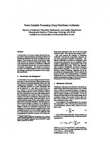
Figure 1. Basic features of the SD-Rtree Figure 1 shows a first example with three successive evolutions. Initially (part A) there is one data node d0 stored on server 0. After the first split (part B), a new server S1 stores the pair (r1 , d1 ) where r1 is a routing node and d1 a data node. The objects have been distributed among the two servers and the tree r1 (d0 , d1 ) follows the classical Rtree organization based on rectangle containment. The directory rectangle of r1 is a, and the directory rectangles of d0 and d1 are respectively b and c, with a = mbb(b ∪ c). The rectangles a, b and c are kept on r1 in order to guide insert and search operations. If the server S1 must split in turn, its directory rectangle c is further divided and the objects distributed among S1 and a new server S2 which stores a new routing node r2 and a new data node d2 . r2 keeps its directory rectangle c and the dr of its left and right children, d and e, with c = mbb(d ∪ e). Each directory rectangle of a node is therefore represented exactly twice: on the node, and on its parent. A routing node maintains the id of its parent node, and links to its left and right children. A link is a quadruplet (id, dr, height, type), where id is the id of the server that stores the referenced node, dr is the directory rectangle of the referenced node, height is the height of the subtree rooted at the referenced node and type is either data or routing. Whenever the type of a link is data, it refers to the data node stored on server id, else it refers to the routing node. Note that a node can be identified by its type (data or routing) together with the id of the server where it resides. When no ambiguity arises, we will blur the distinction between a node id and its server id. The description of a routing node is as follows: Type: ROUTING N ODE height, dr: description of the routing node left, right: links to the left and right children parent_id: id of the parent routing node
OC: the overlapping coverage The routing node provides an exact local description of the tree. In particular the directory rectangle is always the geometric union of left.dr and right.dr, and the height is Max(left.height, right.height)+1. OC, the overlapping coverage, to be described next, is an array that contains the part of the directory rectangle shared with other servers. The type of a data node is as follows: Type: DATA N ODE data: the local dataset dr: the directory rectangle parent_id: id of the parent routing node OC: the overlapping coverage
moved to the data repository of S ′ . A new routing node rS ′ is stored on S ′ and becomes the immediate parent of the data nodes respectively stored on S and S ′ . A
B
C
null empty
empty
d0
1
1
empty
d0
Server 0
Server 0
Server 0
null
null
1
right r1 1
d1
left 0
Server 1
The image An important concern when designing a distributed tree is the load of the servers that store the routing nodes located at or near the root. These servers are likely to receive proportionately much more messages. In the worst case all the messages must be first routed to the root. This is unacceptable in a scalable data structure which must distribute evenly the work over all the servers. An application that accesses an SD-Rtree maintains an image of the distributed tree. This image provides a view which may be partial and/or outdated. During an insertion, the user/application estimates from its image the address of the target server which is the most likely to store the object. If the image is obsolete, the insertion can be routed to an incorrect server. The structure delivers then the insertion to the correct server using its actual routing node at the servers. The correct server sends back an image adjustment message (IAM) to the requester. Point and window queries also rely on the image to find quickly a server whose directory rectangle satisfies the query predicate. A message is then sent to this server which carries out a local search, and routes the query to other nodes if necessary. An image is a collection of links, stored locally, and possibly organized as a local index if necessary. Each time a server S is visited, the following links can be collected: the data link describing the data node of S, the routing link describing the routing node of S, and the left and right links of the routing node. These four links are added to any message forwarded by S. When an operation requires a chain of n messages, the links are cumulated so that the application finally receives an IAM with 4n links. Node splitting When a server S is overloaded by new insertions in its data repository, a split must be carried out. A new server S ′ is added to the system, and the data stored on S is divided in two approximately equal subsets using a split algorithm similar to that of the classical Rtree [6, 5]. One subset is
2
parent
parent left 0
d0
r1
right 1
d1
Server 1 1
2 parent
routing link
data link
routing node
data node
parent
left 1
right r2 2
d2
Server 2
Figure 2. Split operations The management and distribution of routing and data nodes are detailed on Figure 2 for the tree construction of Figure 1. Initially (part A), the system consists of a single server, with id 0. Every insertion is routed to this server, until its capacity is exceeded. After the first split (part B), the routing node r1 , stored on server 1, keeps the following information (we ignore the management of the overlapping coverage for the time being): • the left and right fields; both are data links that reference respectively servers 0 and 1, • its height (equal to 1) and its directory rectangle (equal to mbb(lef t.dr, right.dr)), • the parent id of the data nodes 0 and 1 is 1, the id of the server that host their common parent routing node. Since both the left and right links are of type data links, the referenced servers are accessed as data nodes (leaves) during a tree traversal. Continuing with the same example, insertions are now routed either to server 0 or to server 1, using a Rtree-like C HOOSE S UBTREE procedure [6, 1]. When the server 1 becomes full again, the split generates a new routing node r2 on the server 2 with the following information: • its left and right data links point respectively to server 1 and to server 2 • its parent_id field refers to server 1, the former parent routing node of the splitted data node.
The right child of r1 becomes the routing node r2 and the height of r1 must be adjusted to 2. These two modifications are done during a bottom-up traversal that follows any split operation. At this point the tree is still balanced. Overlapping coverage We cannot afford the traditional top-down search in a distributed tree because it would overload the nodes near the tree root. Our search operations attempt to find directly, without requiring a top-down traversal, a data node d whose directory rectangle dr satisfies the search predicate. However this strategy is not sufficient with spatial structures that permit overlapping, because d does not contain all the objects covered by dr. We must therefore be able to forward the query to all the servers that potentially match the search predicate. This requires the distributed maintenance of some redundant information regarding the parts of the indexed area shared by several nodes, called overlapping coverage (OC) in the present paper. A simple but costly solution would be to maintain, on each data node d, the path from d to the root of the tree, including the left and right regions referenced by each node on this path. From this information we can deduce, when a point or window query is sent to d, the subtrees where the query must be forwarded. We improve this basic scheme with two significant optimizations. First, if a is an ancestor of d or d itself, we keep only the part of d.dr which overlaps the sibling of a. This is the sufficient and necessary information for query forwarding. If the intersection is empty, we simply ignore it. Second we trigger a maintenance operation only when this overlapping changes. a. Initial tree
11 00 00 11 00 11
C
A D
c. Extension of D
b. Split of B R
C
A
R
D B
D
E B
C
A
F
P
11 00 01 00 11 00 11 B
R E F
Figure 3. Overlapping coverage examples Figure 3 illustrates the concept. The left part shows a two-levels tree rooted at R. The overlapping coverage of A and B, A.dr ∩ B.dr, is stored in both nodes. When a query (say, a point query) is transmitted to A, A knows from its overlapping coverage that the query must be routed to B if the point argument belongs to A ∩ B. Next, consider the node D. Its ancestors are A and R. However the subtrees which really matter for query forwarding are C and B, called the outer subtrees of, respectively, A and R with respect to D. Since D.dr ∩ C.dr = ∅ and D.dr ∩B.dr = ∅, there is no need to forward any query whose argument (point or window) is included in D.dr. An important feature is that the content of B, the outer subtree of R with respect to A, can evolve independently
from A, as long as the rectangle intersection remains the same. Figure 3.b shows a split of the server B: its content has been partially moved to the new data node E, and a new routing node F has been inserted. There is no need to propagate any update of the OC to the subtree rooted at A. Finally the subtree rooted at A may also evolve. Figure 3.c shows an extension of D such that the intersection with F is no longer empty. However our insertion algorithm guarantees that no node can make the decision to enlarge its own directory rectangle without referring first to its parent. Therefore the object’s insertion which triggers the extension of D has first been routed to A. Because A knows the space shared with F , it can transmit this information to its child D, along with the insertion request. Formally, given a node N , let anc(N ) = {N1 , N2 , . . . , Nn } be the set of ancestors of N . Each node Ni ∈ anc(N ) has two children. One is itself an ancestor of N or N itself, while its sibling is not an ancestor of N and is called the outer node, denoted outerN (Ni ). For instance the set of ancestors of d2 in Figure 1 is {r1 , r2 }. The outer node outerd2 (r2 ) is d1 , the outer node outerd2 (r1 ) is d0 . The overlapping coverage of N is an array OCN of the form [1 : oc1 , 2 : oc2 , · · · , n : ocn ], such that oci is N.dr ∩ outerN (Ni ).dr. Moreover an entry i is represented in the array only if oci 6= ∅. Each node stores its overlapping coverage which is maintained as follows. When an object obj must be inserted in a subtree rooted at N , one first determines with C HOOS E S UBTREE the subtree I where obj must be routed. O, the sibling of I, is therefore the outer node with respect to the leaf where obj will be stored. The node I must possibly be enlarged to accommodate obj and this leads to check whether the intersection I.dr ∩ O.dr has changed as well, in which case the overlapping coverage must be modified as follows: 1. the OC entry [O.id : I.dr ∩ O.dr] is added to the insertion message routed to the child I 2. a OC update message, containing the OC entry [I.id : I.dr ∩ O.dr], is sent to the child O. The operation is called recursively until a data node is reached. The cost of the OC maintenance depends both on the length of the insertion path to the chosen data node d, and on the number of enlargements on this path. In the worst case, the insertion path starts from the root node, and all the overlaps between d and its outer nodes are modified, which result at worse in N − 1 messages. However, in practice, the cost is limited because the insertion algorithm avoids in most cases a full traversal of the tree from the root to a data node d, and reduces therefore the number of ancestors
of d that can possibly be enlarged. Our experiments confirm that the overlapping coverage remains stable when the embedding space is fully covered, making the cost of OC maintenance negligible. Balancing In order to preserve the balance of the tree, a rotation is sometimes required during the bottom-up traversal that adjusts the heights. The balancing of the SD-Rtree takes advantage of the absence of order on rectangles which gives more freedom for reorganizing an unbalanced tree, compared to classical AVL trees. The technique is described with respect to a rotation pattern which is a subtree of the form a(b(e(f,g),d),c) satisfying the following conditions for some n ≥ 1: • height(c) = height(d) = height(f ) = n − 1 • height(g) = max(0, n − 2) a
n+2
n
b
n+1 b
n+1
c
n+1
n
e
d
e
a
n−1
n
n−1
f
d
g
c
n−1
n−1
n−2
n−1
n−1
f
g
n−1
n−2 a
c g
b f
c g
e
d
f e
d
a. The rotation pattern a(b(e(f,g), d), c)
b. Choice move(g)=b(e(f,d), a(g,c))
b
b
n+1
n+1
e
n+1
n+1
e
a
a
f
g
d
c
g
d
f
c
n−1
n−2
n−1
n−1
n−2
n−1
n−1
n−1
a
a
c g f
c g
e
d
d
c. Choice move(d)=b(e(f,g), a(d,c))
The proposition shows that the management of unbalanced nodes always reduces to a balancing of a rotation pattern a(b(e(f,g),d),c). The operation is as follows: 1. b becomes the root of the reorganized subtree, 2. The routing node a becomes the right child of b; e remains the left child of b and c the right child of a, 3. One determines which one of f, g or d should be the sibling of c in the new subtree. The chosen node becomes the left child of a, the other pair constitutes the children of e. The choice of the moved node should be such that the overlapping of the directory rectangles of e and a is minimized. Tie-breaking can be done by considering the minimization of the dead space as second criteria. This rotation mechanism can somehow be compared to the forced reinsertion strategy of the R*tree [1], although it is here limited to the scope of a rotation pattern. Any pairwise combination of f, g, d and c yields a balanced tree. The three possibilities, respectively called move(g), move(d) and move(f) are shown on Figure 4. The choice move(g) (Figure 4.b) is the best one for our example. All the information that constitute a rotation pattern is available from the left and right links on the bottom-up adjust path that starts from the splitted node. The balancing can be obtained in exactly 6 messages for move(f) and move(g), and 3 messages for move(d) because the subtree rooted at e remains in that case the same. When a node a receives an adjust message from its modified child (b in our example), it knows the right link c and gets the links for e, d, f and g which can be maintained incrementally in the chain of adjustment messages. If a detects that it is unbalanced, it takes account of the information represented in the links to determine the subtree f, g or d which becomes the sibling of c. The overlapping coverage must also be updated for the subtrees rooted at f, d, g and c.
f e
d. Choice move(f)=b(e(g,d), a(f,c))
Figure 4. Balancing in the SD-Rtree An example of rotation pattern is shown on Figure 4. Note that a, b and e are routing nodes. Now, assume that a split occurs in a balanced SD-Rtree at node s. A bottom-up traversal is necessary to adjust the heights of the ancestors of s. Unbalanced nodes, if any, will be detected during this traversal. The following holds: Proposition 1 Let a be the first unbalanced node met on the adjustment path that follows a split. Then the subtree rooted at a matches a rotation pattern.
3 Algorithms We present now the algorithms for the insertion, deletion, point and window queries. Recall that all these operations rely on an image of the structure in order to remain as much as possible near the leaves in the tree, avoiding the root overloading. These operations also adjust the image through IAMs to better reflect the current structure. The main SD-Rtree variant considered in what follows maintains an image on the client component, although we shall investigate in our experiments another variant that stores an image on each server component. Initially a client C knows only its contact server. The IAMs extend this
knowledge and avoid to flood this server with insertions that must be forwarded later on. Insertion In order to insert an object o with rectangle mbb, C searches its local image as follows: 1. all the data links in the image are considered first; if a link is found whose directory rectangle contains mbb, it is kept as a candidate; when several candidates are found, the one with the smallest dr is chosen;
S2 cannot make the decision to insert o, because o.mbb is not contained in d2 .dr. Then S2 initiates a bottom-up traversal of the SD-Rtree until a routing node whose dr covers o is found (node c on the figure). A classical insertion algorithm is performed on the subtree rooted at c. The outof-range path (ORP) consists of all the servers involved in this chain of messages. Their routing and data links constitute the IAM which is sent back to C. r
... c
2. if no data link has been found, the list of routing links are considered in turn; among the links whose dr contains mbb, if any, one chooses those with the minimal height (i.e., those which correspond to the smallest subtrees); if there are still several candidates, the one with the smallest dr is kept; The rationale for these choices is that one aims at finding the data node which can store o without any enlargement. If it happens that several choices are possible, the one with the minimal coverage is chosen because it can be estimated to be the most accurate one. If the above investigations do not find a link that covers mbb, the data link whose dr is the closest to mbb is chosen. Indeed one can expect to find the correct data node in the neighborhood of d, and therefore in the local part of the SD-Rtree. If the selected link is of type data, C addresses a message I NSERT-I N -L EAF to S; else the link refers to a routing node and C sends a message I NSERT-I N -S UBTREE to S. • (I NSERT-I N -L EAF message) S receives the message; if the directory rectangle of its data node dS covers actually o.mbb, S can take the decision to insert o in its local repository; there is no need to make any other modification in the distributed tree (if no split occurs); else the message is out of range, and a message I NSERT-I N -S UBTREE is routed to the parent S ′ of dS ; • (I NSERT-I N -S UBTREE message) when a server S ′ receives such a message, it first consults its routing node rS ′ to check whether its directory rectangle covers o; if no the message is forwarded to the parent until a satisfying subtree is found (in the worst case one reaches the root); if yes the insertion is carried out from rS ′ using the classical Rtree top-down insertion algorithm. During the top-down traversal, the directory rectangles of the routing nodes may have to be enlarged. If the insertion could not be performed in one hop, the server that finally inserts o sends an acknowledgment to C, along with an IAM containing all the links collected from the visited servers. C can then refresh its image. The insertion process is shown on Figure 5. The client chooses to send the insertion message to S2 . Assume that
Client
a
s1 s2 s3 s4 s5
S1
S2
...
...
b
ORP
image
S3
S4
...
S5
insertion message Image Adjustment Message
Figure 5. The insertion algorithm Initially the image of C is empty. The first insertion query issued by C is sent to the contact server. More than likely this first query is out of range and the contact server must initiate a path in the distributed tree through a subset of the servers. The client will get back in its IAM the links of this subset which serve to construct its initial image. An image becomes obsolete as splits occur and new servers join the structure. One expects that the out-of-range path remains local and involves only the part of the tree that changed with respect to the client image. In the worst case a client C sends to a server S an outof-range message which triggers a chain of unsuccessful I NSERT-I N -S UBTREE messages from S to the root of the SD-Rtree. This costs log N messages. Then another set of log N messages is necessary to find the correct data node. Finally, if a split occurs, another bottom-up traversal might be required to adjust the heights along the path to the root. The worst-case results thus in O(3 log N ) messages. However, if the image is reasonably accurate, the insertion is routed to the part of the tree which should host the inserted object. This results in a short out-of-range path with few messages. The strategy reduces the workload of the root that is accessed only for objects that fall outside the boundaries of the most-upper directory rectangles. Deletion Deletion is similar to that in an R-Tree [6]. A server S from which an object has been deleted may adjust covering rectangles on the path to the root. It may also eliminate the node if it has too few objects. The SD-Rtree relocates then the remaining objects to its sibling S ′ in the binary tree. Node S ′ becomes the child of its grandparent. An adjustment of the height is propagated upward as necessary,
perhaps requiring a rotation. Point queries The point query algorithm uses a basic routine, PQT RAVERSAL, which is the classical point-query algorithm for Rtree. At each node, one checks whether the point argument P belongs to the left (resp. right) child’s directory rectangle. If so the routine is called recursively for the left (resp. right) child node. First, the client searches its image for a data node d whose directory rectangle contains P , according to its image. A point query message is sent to the server Sd (or to its contact server if the image is empty). Two cases occur. (i) The data node rectangle on the target server contains P . Then the point query applies locally to the data repository. PQT RAVERSAL must also be routed to the outer nodes o in the overlapping coverage array d.OC whose rectangle contains P as well. (ii) An out-of-range occurs (the data node on server Sd does not contain P ). The SD-Rtree is then scanned bottom-up from Sd until a routing node r that contains P is found. A PQT RAVERSAL is then applied from r, and from the outer nodes in the overlapping coverage array r.OC whose directory rectangle contains P . In this way all the parts of the SD-Rtree which may contain P are visited. The overlapping coverage information stored at each node usually avoids to traverse the whole path starting at the root as it will appear. With an up-to-date client image, the target server is correct. The number of PQT RAVERSALs performed depends on the amount of overlapping with the leaf ancestors. In general 1 message sent to the correct server should suffice for the accurate image, and O(log N ) messages for an outdated one. Window queries Given a window W , the client searches its image for a link to a node that contains W . A query message is sent to the server that hosts the node. An out-of-range may occur because of image inaccuracy, in which case a bottom-up traversal is initiated. When a routing node r that actually covers W is found, the subtree rooted at r, as well as the overlapping coverage of r, allow the navigation to the appropriate data nodes. The algorithm is given below. It applies also, with minimal changes, to point queries. The routine WQT RAVERSAL is the classical Rtree window query algorithm adapted to our distributed context. W INDOW Q UERY (W : rectangle) Input: a window W Output: the set of objects whose mbb intersects W begin // Find the target server targetLink := C HOOSE F ROM I MAGE(Client.image, W ) // Check that this is the correct server. Else move up the tree
node := the node referred to by targetLink; while (W 6⊆ node.dr and node is not the root) // out of range node := parent(node) endwhile // Now node contains W , or node is the root if (node is a data node) Search the local data repository node.data else // Perform a window traversal from node WQT RAVERSAL (node, W ) end // Always scan the OC array, and forward for each (i, oci ) in node.OC do if (W ∩ oci 6= ∅) then WQT RAVERSAL (outernode (i), W ) endif end for end
The number of data nodes which intersect W depends on the size of W . Once a node that contains W is found, the WQT RAVERSAL is broadcast towards these data nodes. The maximal length of each of these message paths is O(log N ). The requests are forwarded in parallel, and result each in an IAM when a data node is finally reached.
4 Experimental evaluation We performed experiments evaluating the behavior of an SD-Rtree over large datasets of 2-dimensional rectangles. We use a simulator written in C. Our datasets are produced by the GSTD generator [15]. The study involved the following variants of the SD-Rtree: BASIC. This variant is implemented for comparison purposes, since the high load of the root levels makes it unsuitable as a SDDS. It does not use images neither on the client nor on the servers. Each request is forwarded to the server that maintains the root node. The top-down traversal of the tree to reach the adequate server follows. I M C LIENT. This is the variant described above. Each client builds an image, and maintains it according to the IAMs. We recall that the servers forward the operations through their routing nodes. I M S ERVER. There is an image on each server component, instead of on the client one. This corresponds to an architecture for many light-memory clients (e.g., PDA) addressing queries to a cluster of interconnected servers. We simulate it by choosing randomly, for each request (insertion or query) a contact server playing the role of a services provider. We studied the behavior of the different variants for insertions ranging from 50,000 to 500,000 objects (rectangles). We also executed against the structure 0-3,000 point and window queries. We measured the number of messages
exchanged. The size of the messages remained, as expected, negligible (at most a few hundreds of bytes). The data node on each server was stored as a main memory R-tree. We fixed the capacity of each server to 3,000 objects. Insertions For the three variants we study the behavior after an initialization of the SD-Rtree with 50,000 objects. This avoids partially the measures distortion due to the cost of the initialization step which affects primarily the first servers. The comparisons between the different techniques are based on the total number of messages received by the servers, and on the load balancing between servers. Figure 6 shows the total number of messages for insertions of objects following a uniform distribution. It illustrates the role of the images. While BASIC requires on average 8 messages when the number of insertions is 500,000, I M S ERVER needs 6 messages on average, thus a 25% gain. The cost of each insertion for the BASIC variant is approximately the length of a path from the root to the leaf. The final, maximal, height of the tree is here 8. Additional messages are necessary for height adjustment and for OC maintenance, but their number remains low.
out to be out-of-range. Using the I M S ERVER variant and the m insersame number of insertions, a server will get only N tions requests (N being the number of servers), and much less adjustment messages. Its image is therefore more likely to be outdated. Our results show that the I M C LIENT variant leads to a direct match in 99.9% of the cases. Table 1 summarizes the characteristics of the SDR-tree variants, initialized as above, for a large number of insertions. With a uniform distribution, the tree grows regularly and its height follows the rule 2height−1 < N ≤ 2height . The average load factor is around 70%, i.e., around the wellknown typical ln 2 value. The BASIC variant requires a few more messages than the height of the tree, because of height adjustment and overlapping coverage maintenance. On the average, the number of messages per insertion is equal to the final height of the tree. With I M S ERVER the number of messages is lower. First a few forwarding messages are sufficient if the contacted node has split, in which case the correct server can be found locally. nb objects 50,000 100,000 150,000 200,000 250,000 300,000 350,000 400,000 450,000 500,000
nb serv. 58 64 108 125 127 166 207 233 240 243
height 6 6 7 7 7 8 8 8 8 8
load(%) 57.5 78.1 61.7 66.7 78.7 70.3 64.4 64.4 69.4 75.4
BASIC 6 6 6 7 7 7 8 8 8 8
I M SERV 3 3 3 4 4 4 5 5 5 5
IMCL 5 3 3 3 3 3 3 3 3 3
Table 1. Number of messages per insertion
Figure 6. Number of messages for insertion With I M S ERVER, each client routes its insertions to its contact server. When the contact server has an up-to-date image of the structure, the correct target server can be reached in 2 messages. Otherwise, an out-of-range occurs and some forwarding messages are necessary along with an IAM. We experimentally find that the average number of additional messages after an out-of-range is for instance 5 with 252 servers and 500,000 insertions. The gain of 25% is significant compared to the BASIC variant, but even more importantly this greatly reduces the unbalanced load on the servers (see below). Maintaining an image on the client ensures a drastic improvement. The average number of messages to contact the correct server decreases to 1 message on average. The convergence of the image is naturally much faster than with I M S ERVER because a client that issues m insertions will get an IAM for the part of these m insertions which turns
Second if no information regarding the correct server can be found in the image, an out-of-range path is necessary. The length of an out-of-range path should be the height of the tree on the average. But the heuristics that consists in choosing the “closest” server in the image (i.e., the one with the smallest necessary directory rectangle enlargement) turns out to be quite effective by reducing in most cases the navigation in the SD-Rtree to a local subtree. Table 1 shows for instance that with a tree of height 7 with 127 servers, only 4 additional messages are necessary to reach the correct server (2 bottom-up, and 2 top-down messages). Finally, the average number of messages for I M C LIENT does not depend on the height of the tree. After a short acquisition step (see the analysis on the image convergence below), the client has collected enough information in its image to contact either directly the correct server, or at least a close one. The difference in the number of messages with the I M S ERVER version lies in the quality of the image, since a client quickly knows almost all the servers. Figure 7 analyzes the distribution of messages with respect to the position of a node in the tree. Using the BA SIC variant, the servers that store the root or other high-
Figure 7. Messages distribution for insertions
level internal nodes have much more work than the others. Basically a server storing a routing node at level n receives twice more messages than a server storing a routing node at level n − 1. This is confirmed by the experiments, e.g., the server that manages the root handles 12.67% of the messages, while the servers that manage its children received 6.38%. Figure 7 shows that maintaining an image (either with I M S ERVER or I M C LIENT) not only allows to save messages, but also distributes much more evenly the workload. The distribution depends actually on the quality of the image. With I M S ERVER, each server S is contacted with equal probability. If the image of S is accurate enough, S will forward the message to the correct server S ′ which stores the object. Since all the servers have on average the same number of objects, it is expected that each server receives approximatively the same number of messages. At this point, for a uniform distribution of objects, the load is equally distributed over the server. The probability of having to contact a routing node N decreases exponentially with the distance between the initially contacted data node and N . The initial insertion of 50,000 objects results in a tree whose depth is 5, hence the lower number of messages for the nodes with height 1, 2 or 3, since they are newer. With I M C LIENT, since a client acquires quickly a complete image, it can contact in most case the correct server. The same remark holds for nodes whose level is 1, 2 or 3 as above. There is a low overhead due to the balancing of the distributed tree. We perform several experiments to evaluate this overhead. With our 3000-objects capacity and 500,000 insertions of uniformly distributed data for instance, we need only 440 messages for updating the heights of the subtrees and 0 for rotations, to maintain the tree balanced, i.e., around 1 message for every 1000 insertions. Experiments with skewed data (not reported here due to space limitations) show a similar behavior of the structure. The only noticeable difference is that more messages are
Figure 8. Cost of query answering
necessary for maintaining the height (640 instead of 440 for 500,000 insertions) and additional messages are required to balance the tree (310). Nonetheless on average, only 1 message per 500 insertions is necessary for maintaining the tree. (in the worst case log(nbservers)) and for balancing since the reorganization remains local. Queries We first created the SD-Rtree accomodating 200,000 objects, uniformly distributed. The tree grew to 107 servers with a maximal height of 7. Then we evaluated up to 3,000 queries. Figure 8 shows the gain of the image-aware variants compared to the BASIC one. Since the tree remains stable (no insertions), we need on average a constant number of messages to retrieve the answer in BASIC. Without overlap, this number could be predicted to be 7, the height of the tree. The overlap costs here 2 additional messages on average. As expected the variants which rely on an image outperform BASIC. The number of messages per query decreases with the number of queries, as the server or the client, depending on the variant, acquires a more faithful image and thus contacts more and more frequently the correct server(s) directly. The convergence is faster for I M C LIENT than for I M S ERVER. I M C LIENT appears very efficient even for a small number of queries. After 3,000 queries, the search with both variants become almost three times faster than with BASIC. Window queries experiments give similar results. The higher cost reported, for all variants, is due to the overlap between the window and the dr of the servers. Figure 9 shows the ratio of correct matches when an image is used for a point query. With I M S ERVER, after 1500 (resp. 2500) queries, every server has an image that permits a correct match in 80% (resp. 95%) of the cases. For I M C LIENT, only 600 queries are necessary, and with 200 queries the structure ensures a correct match for 80% of the queries. This graph confirms the results of Figure 8. The results are especially good for I M C LIENT even when the
scheme. The practicality of the related trade-offs remains to be determined. Acknowledgment: The CERIA work was partly supported by MS Research Grant and by CEE eGov-Bus project IST 26727STP. We thank Nick Roussopoulos and anonymous referees for helpful suggestions.
References
Figure 9. Good matches for point queries number of queries is low.
Figure 10. Messages distribution for queries Finally, Figure 10 confirms that using an image serves a satisfying load balancing, for the same reasons already given for the insertion algorithm.
5 Conclusion The SD-Rtree provides the Rtree capabilities for large spatial data sets stored over interconnected servers. The distributed addressing and specific management of the nodes with the overlapping coverage avoid the centralized calculus. The analysis, including the experiments, confirmed the efficiency of our design choices. The scheme should fit the needs of new applications of spatial data, using endlessly larger datasets. Future work on SDR-tree should include other spatial operations: kNN queries, distance queries and spatial joins. One should study also more in depth the concurrent distributed query processing. As for other well-known data structures, additions to the scheme may perhaps increase the efficiency in this context. A final issue relates to the fanout of our structure. The binary choice advocated in the present paper favors an even distribution of both data and operations over the servers. A larger fanout would reduce the tree height, at the expense of a more sophisticated mapping
[1] N. Beckmann, H. Kriegel, R. Schneider, and B. Seeger. The R*tree : An Efficient and Robust Access Method for Points and Rectangles. In SIGMOD, pages 322–331, 1990. [2] A. Crainiceanu, P. Linga, J. Gehrke, and J. Shanmugasundaram. Querying Peer-to-Peer Networks Using P-Trees. In Proc. Intl. Workshop on the Web and Databases (WebDB), pages 25–30, 2004. [3] R. Devine. Design and Implementation of DDH: A Distributed Dynamic Hashing Algorithm. In Foundations of Data Organization and Algorithms (FODO), 1993. [4] V. Gaede and O. Guenther. Multidimensional Access Methods. ACM Computing Surveys, 30(2), 1998. [5] Y. Garcia, M. Lopez, and S. Leutenegger. On Optimal Node Splitting for R-trees. In VLDB, 1998. [6] A. Guttman. R-trees : A Dynamic Index Structure for Spatial Searching. In SIGMOD, pages 45–57, 1984. [7] S. E. Hambrusch and A. A. Khokhar. Maintaining Spatial Data Sets in Distributed-Memory Machines. In Proc. Intl. Parallel Processing Symposium (IPPS), 1997. [8] H. Jagadish, B. C. Ooi, and Q. H. Vu. BATON: A Balanced Tree Structure for Peer-to-Peer Networks. In VLDB, pages 661–672, 2005. [9] H. Jagadish, B. C. Ooi, Q. H. Vu, R. Zhang, and A. Zhou. VBI-Tree: A Peer-to-Peer Framework for Supporting MultiDimensional Indexing Schemes. In Proc. Intl. Conf. on Data Engineering (ICDE), 2006. [10] J. S. Karlsson. hQT*: A Scalable Distributed Data Structure for High-Performance Spatial Accesses. In Foundations of Data Organization and Algorithms (FODO), 1998. [11] V. Kriakov, A. Delis, and G. Kollios. Management of Highly Dynamic Multidimensional Data in a Cluster of Workstations. In EDBT, pages 748–764, 2004. [12] W. Litwin and M.-A. Neimat. k-RP*S: A Scalable Distributed Data Structure for High-Performance MultiAttribute Access. In Proc. Intl. Conf. on Parallel and Distributed Inf. Systems (PDIS), pages 120–131, 1996. [13] W. Litwin, M.-A. Neimat, and D. A. Schneider. RP*: A Family of Order Preserving Scalable Distributed Data Structures. In VLDB, pages 342–353, 1994. [14] W. Litwin, M.-A. Neimat, and D. A. Schneider. LH* A Scalable, Distributed Data Structure. ACM Trans. on Database Systems, 21(4):480–525, 1996. [15] Y. Theodoridis, J. R. O. Silva, and M. A. Nascimento. On the Generation of Spatiotemporal Datasets. In Proc. Intl. Conf. on Large Spatial Databases (SSD), 1999.