the tools in today's iterative development processes thus requires manual ... Up to 98% of all processors are built into embedded systems [1,2]. Many of these ... the modeling process which describes how to create the artifacts step by step .... software architecture, and refines them to obtain a platform-independent model.
Seamless Model-driven Development put into Practice Wolfgang Haberl1 , Markus Herrmannsdoerfer1 , Stefan Kugele1 , Michael Tautschnig2 , and Martin Wechs3 1
2
Institut f¨ ur Informatik Technische Universit¨ at M¨ unchen Boltzmannstr. 3, 85748 Garching b. M¨ unchen, Germany Formal Methods in Systems Engineering, Faculty of Informatics Vienna University of Technology Favoritenstr. 9, 1060 Wien, Austria 3 BMW Forschung und Technik GmbH Hanauer Straße 46, 80992 M¨ unchen, Germany
Abstract Model-driven development (MDD) today is the most promising approach to handle the complexity of software development for distributed embedded systems. Still, no single tool-chain exists that meets all needs of companies employing MDD. Moving back and forth between the tools in today’s iterative development processes thus requires manual integration steps, which are error-prone and hamper reuse and refinement of models. A possible workaround is developing adapters for each pair of tools. Despite its large overhead, industry started pursuing this approach because of a lack of better alternatives. A proper solution is a tool-chain building on an integrated modeling language. We have realized this in cooperation with BMW Research and Technology. To increase the degree of automation during development, the modeling language builds upon a core featuring a rigorous semantics. This enables automatic analysis, facilitating an automatic transition from model-based designs to a distributed system running on the target platform.
1
Introduction
As embedded systems, ranging from music players and mobile phones over cardiac pacemakers to airbag controllers, become ubiquitous, the need for quality escalates. Up to 98% of all processors are built into embedded systems [1,2]. Many of these perform mission-critical tasks in systems such as flight controllers or air condition systems in premium-class cars. In such large-scale safety-critical systems, an imminent need for quality and absence of errors meets the complexity of developing software for distributed systems. In industry, model-driven development (MDD) is seen as the most promising technique to tackle this complexity. Consequently, software industry created a wide range of tools to aid the developer in many steps of an MDD process. Still, there is not a seamless tool-chain, let alone an integrated tool, covering the entire
development process from requirements and design models to code executable on the target platform. Instead, developers must deal with a multitude of tools, which requires converting process artifacts back and forth as the product evolves. Industry tries to work around these largely manual steps by building tool adapters. This approach may seem to be the simplest at first sight, but it is surely not future-proof. This is, however, the least of a problem: in fact, it is often technically unsound. An automated translation between tools requires that the underlying modeling languages have well-defined and compatible semantics. As this is often not the case, each transition—be it manual or automatic—bears the risks of loss of information and inadvertent introduction of additional errors. Looking at the amount and structure of warranty costs in the automotive domain, a need for improvement is imminent: billions of dollars are spent for warranty costs each year. These costs amount to a total of up to US$ 500 per vehicle [3]. According to IBM research, about 30% of these costs are attributable to software and electronics defects. With current tools, a decrease in the number of implementation errors seems largely out of reach. In industrial embedded systems development, however, not only the number of design and implementation errors poses a challenge. Architectural and cost constraints require optimization at system level. Due to the isolation of tools, currently optimization can only be applied locally. In consequence, automatic global optimizations—such as fewer and cheaper controllers, smaller packaging, or reduced weight—are impossible. As the amount of software in cars continues to grow exponentially, improved tools alone will not suffice. Instead, an appropriate development process and corresponding tool support will be required. Especially in the automotive domain, struggling with the enormous cost pressure, this is an important issue. Short product cycles require that iterative processes have both short and few iterations, requiring best possible automation at low overhead. All these facts collide with the state-of-the-art, where manual and error prone conversion is involved. In cooperation with BMW Research and Technology, we developed an approach to overcome those hurdles. In this paper we give an overview of our process and tool chain. We refer to previous publications describing specific technical aspects in detail where appropriate.
2
Requirements for Seamless Model-driven Development
To tackle these, we propose a seamless model-driven development approach [4]. Starting from requirements and continuing to design and code generation, deep integration of all constituents is required. More specifically, this is required for – the modeling language which provides an easy-to-use syntax and a welldefined semantics for all artifacts, – the modeling process which describes how to create the artifacts step by step using the modeling language, and – the modeling tool which supports the developer to author the artifacts and automates the process steps as far as possible.
In the following, we will detail on the necessary prerequisites to provide integration for each of these constituents. Integrated Modeling Language. An integrated modeling language enables integration of all artifacts created during the development process. The integrated modeling language shall rigorously define the syntactic structure of all artifacts as well as their relation. Moreover, a concrete syntax that visualizes the artifacts in a human-understandable way has to be provided by the integrated modeling language. It needs to be based on a common modeling theory giving the artifacts a precise semantics. First, this theory is essential to prove properties over all kinds of artifacts created along different process steps. Second, model transformation as well as code generation require a common modeling theory to ensure preservation of semantics when advancing between process steps. The integrated modeling language must support all process steps in a seamless manner to enable an integrated modeling process. Integrated Modeling Process. An integrated modeling process is required to seamlessly develop an embedded system in a stepwise manner. The integrated modeling process needs to define the interplay of all the process steps necessary to create the desired artifacts. Each process step needs to be defined in a way such that it can be either automated by a model transformation or at least supported by the modeling tool. The integrated modeling process must be able to cope with the stringent constraints of embedded systems on reliability, robustness, correctness, and an overall optimized system with respect to execution time and resource usage. Building on the well-defined semantics of the modeling language, verification is performed continuously together with design and implementation activities. Consequently, many design errors can already be ruled out at higher levels of abstraction, reducing cost induced by correcting these errors at a later stage. Integrated Modeling Tool. An integrated modeling tool is required to provide seamless tool support for the development of all artifacts. It needs to be based on a central repository that contains all artifacts and their relationships. The central repository avoids redundancy and inconsistency that results from parallel modification of artifacts by different developers. All the authoring and transformation tools provided by the integrated modeling tool need to operate directly on this central repository—supervised by a well-defined concurrency control. Moreover, seamless change and configuration management is only possible by maintaining all the artifacts in the central repository. The integrated modeling tool shall further enable pervasive tool support to guide the engineers throughout the modeling process.
3
Realization of Seamless Model-driven Development
Following the requirements listed in the preceding section, we describe a solution to the problems stated in Section 1. We first give a short account of the inte-
grated modeling language COLA, and then outline its use in both the integrated modeling process and the integrated modeling tool. 3.1
COLA – The Component Language
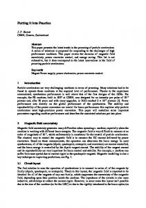
COLA, the COmponent LAnguage, is an integrated modeling language for the design of distributed, safety-critical real-time systems. The key concepts of COLA follow those of well-known modeling languages, such as FODA [5] and Lustre [6]. The resulting language is structured into different layers of abstraction along which a system is modeled. These layers help to reduce the complexity involved in the design of large-scale embedded systems. Each abstraction layer focuses on a certain aspect, and adds new detail to the information contained in higher layers. COLA defines three layers of abstraction which are called Feature Architecture (FA), Logical Architecture (LA), and Technical Architecture (TA), as proposed by Pretschner et al. [7] and Broy et al. [8]. Figure 1 illustrates the core modeling constructs of each layer, and the relations between them, in screenshots from our integrated modeling tool. COLA is based on the synchronous data-flow paradigm and has a welldefined semantics [9]. It is assumed that operations start at the same instant of time and are performed simultaneously, respecting data dependencies. The computation of the system over time can be subdivided into discrete steps, called ticks. The execution is performed in a stepwise manner over a discrete uniform time-base. Feature Architecture (FA). The Feature Architecture formalizes functional requirements on behavior observable at the system boundary [10]. Similar to FODA [5], the overall system behavior is decomposed into a hierarchy of features to reduce complexity. A feature is a function which is observable by the customer at the system boundary. The inner nodes of the tree are composite features which are decomposed into sub-features. The leaves of the tree represent atomic features which cannot be decomposed further and model a function accessible to the customer. Figure 1 depicts the graphical representation of an example feature hierarchy. In the graphical syntax of COLA, the feature hierarchy is represented as a tree, the sub-feature relationship as lines with a diamond, and features as rounded rectangles. In a complex system, however, features are not independent, but rather influence each other. These dependencies are represented as arrows between the corresponding features (see Figure 1). We extended FODA to be able to rigorously define the behavior of atomic and composite features as well as feature dependencies. To ease the transition to the next layer, the behavior is defined by means of constructs provided by the LA, e. g., data-flow networks. Logical Architecture (LA). The Logical Architecture maps features onto a software architecture, and refines them to obtain a platform-independent model of the overall system functionality. The constructs to model the system functionality are based on Lustre [6]. The system can be successively decomposed into or composed of modular units. These units may be defined in-place, as described
Composite Feature Atomic Feature Dependency
Sub-unit
Channel
Network
Automaton State
Transition
Bus
Allocation
Feature Architecture (FA) Logical Architecture (LA) Technical Architecture (TA)
Feature Hierarchy
Cluster
ECU
Hardware Architecture
Cluster Architecture
Figure 1. Integrated Modeling Language COLA
next, or taken from user-defined libraries, which enable reuse. The behavior of a unit is hidden behind the unit’s interface which is defined by a number of typed input and output ports. Figure 1 depicts the graphical representation of a number of units: interfaces are represented as rounded rectangles and ports as triangles. The root unit of a system does not have any unconnected input or output ports, but communicates with the environment using so-called sources and sinks. These sources and sinks model sensor and actuator interaction. COLA defines three kinds of units: networks, automata, and blocks. A system can be decomposed into smaller units, establishing data-flow networks. These smaller units are called sub-units of the network, which are connected by channels. A channel connects an output port with one or more suitably typed (cf. [11]) input ports. The synchronous semantics of COLA define
communication over channels to take no time. Channels determine data-flow dependencies between sub-units and induce a causal order of execution. Feedback loops of channels (transitively) connecting an output port of a unit to an input port of the same unit must contain a delay block which defers propagation by one time interval. A delay serves as data storage: it retains values from one tick to the next. Figure 1 depicts the graphical representation of an example network: sub-units are represented by rounded rectangles, and channels by lines connecting the sub-units. Control flow in networks is modeled by automata. An automaton consists of a number of states where exactly one is active at a time. The automaton’s behavior is defined by the currently active state. Each state is implemented by a sub-unit. Transitions determine how the activated state of an automaton may change over time. The condition for a transition is again implemented by a unit, the evaluation of which is based on the inputs of the automaton. The semantics of COLA requires to check for possible transitions before evaluating the activated state’s behavior. Figure 1 depicts the graphical representation of an example automaton: states are represented by ellipses, and transitions by arrows. COLA provides a number of basic building blocks, e. g., arithmetic or Boolean operators. These blocks execute their respective operation based on the values present at the input ports and emit the according result at their output port. In the course of computation, a unit may act differently depending on its history. Such units are considered stateful. In COLA, only delays and automata retain information of previous computations; all other kinds of units are stateless. Note that a unit containing a stateful sub-unit becomes stateful as well. Technical Architecture (TA). The Technical Architecture maps system functionality, specified by the LA, onto a hardware platform. As shown in Figure 1, the TA consists of Hardware Architecture, Cluster Architecture, and Allocation. The Hardware Architecture describes the structure and the properties of the target hardware platform. The main construct of the Hardware Architecture is the electronic control unit (ECU) which forms a computing node of the distributed platform and can be composed of processors, sensors, and actuators. Sensors and actuators model interaction with the environment, whereas processors execute the system functionality. ECUs can be connected via a bus which provides a communication mechanism. The characteristics of each hardware element, e. g., the resources provided by a processor, can be determined by a number of properties, e. g., clock frequency, storage capacity, etc. The Cluster Architecture partitions the system functionality—as defined in the LA—into distributable entities, called clusters. These will be mapped to the electronic control units of the Hardware Architecture. The Cluster Architecture may be specified manually by the developer, or can be derived automatically from the LA based on characteristics specified in the Hardware Architecture, such as available processing speed or memory. In the latter case, the derivation of the Cluster Architecture can be performed based on some optimization criteria, like for example shortest average turnaround time for all tasks on all nodes, or equally distributed memory consumption for all nodes.
The Allocation establishes the relationship between the Cluster Architecture and the Hardware Architecture. Therefore the Allocation maps each cluster onto an ECU. For the Allocation to be valid, the resources provided by each ECU, like computing power, memory, etc., have to match the resource requirements of the clusters placed thereon for all nodes of the system. To estimate the resource requirements of a cluster, its worst-case execution time (WCET) needs to be calculated. The Allocation can then be automatically generated based on both Hardware and Cluster Architecture taking into account optimization criteria. 3.2
Model Analysis and System Synthesis
The automated transition from a modeled system to executable code is supported by our integrated modeling tool. This transition directly follows the proposed process. We will detail on the necessary steps below, due to space limitations focusing on the transformation from the LA down to an executable system. The artifacts arising during the described transition are depicted in Figure 2. Model Analysis. The formal semantics of our modeling language enables automatic analysis. For such a technique to be useful for the systems engineer, it must not only report the presence of errors, but also yield diagnostic information, i. e., provide the reason of a problem. Furthermore, we require all analyses to be push-button. We have implemented a stack of such methods in our tool. First, consistency checks according to constraints, which are part of our formal modeling language, are performed. This analysis reports syntax errors and violated model invariants. On top of our modeling language we provide a static type system with type variables, which includes an extension to support physical units. Automatic type inference detects and diagnoses errors at interconnected component interfaces, i. e., syntactically incompatible interfaces [11]. To complement these syntactic checks, COLA enables several static semantic analyses: we have implemented a check to verify the absence of nondeterminism in the modeled automata. This analysis reports states of automata that may have more than one activated outgoing transition at the same time. Such behavior must be avoided as code generated from the model would otherwise define the order of execution in a non-foreseeable manner. Further we interface with model checkers to verify the conformance of a design to requirements expressed in SALT (Structured Assertion Language for Temporal Logic) [12]. This analysis is fully automatic and the model checker will return a counterexample for any unsatisfied requirement, which helps to diagnose the underlying problem. We augment static analysis with dynamic methods for early validation. Our tool contains a simulation engine [13] which enables step-wise execution of the system according to its formal semantics using (i) manually set input data, (ii) values obtained in random testing, (iii) data fed back by an environment model, or (iv) simulation based on traces of previous runs on the target platform. The formal semantics not only facilitate bug hunting at model level, but also allow for early performance analysis, automatic computation of allocations of distributable software components to the hardware platform given in the TA, and
Software Model and Hardware Model
Checked Model
Model Analysis
+ ECU 1
ECU 2
ECU 3
System Partitioning Runtime Data Logging Partitioned Model
Executable System
Code Generation
System Synthesis
Source Code Files
System Schedule ECU 1
.c
ECU 2 ECU 3
Scheduling
Resource Estimation
Distribution Decision Resource Usage Figures
System Distribution ECU 1
ECU 2
ECU 3
Figure 2. Artifacts generated along the development process; solid arrows depict regular workflow while dashed arrows indicate optional refinement iterations
automatic scheduling. Furthermore, executable code and platform configuration are generated automatically. These techniques are detailed in the following. System Partitioning and Code Generation. Using the information of both LA and TA, automatic system synthesis can be performed. Initially, code for each distributable software component specified in the Cluster Architecture is generated [14]. To test correctness of code generation, we also implemented an I/O conformance tester building upon the TorX ioco test framework [15]. Calls to a middleware realize both interaction of distributed software components and interfacing with sensors and actuators. These calls are injected into the code during system synthesis, as introduced in [16]. The middleware also retains the state of the components between cyclic invocations and provides a global clock for timely execution of time-triggered tasks. Resource Estimation. The resource requirements of each distributable software component have to be evaluated for subsequent distribution and scheduling decisions. Automated performance estimation calculates the worst-case execution time and memory consumption of each component. Using the SciSim [17] framework, the generated code is instrumented and analyzed to compute its resource usage for every processing node the component might be executed on. System Distribution. Based on this resource estimation, an optimal placement of distributable software components to run on computing nodes modeled in the Hardware Architecture is computed (cf. [18]). We use an integer linear programming solver to determine a solution yielding minimal cost under the hardware capability constraints. This includes their processing power and memory, as well as the communication systems interconnecting the nodes. It may turn out that no distribution of components exists that satisfies all constraints. In that case another refinement iteration is necessary as depicted in Figure 2. Scheduling. Once a placement of software components has been determined, a suitable schedule is computed for each processing node. In doing so, data- and control flow dependencies must be considered, using the technique described in [19] to guarantee preservation of semantics on the target system. We use a satisfiability modulo theories (SMT) solver to determine a valid schedule. The result guarantees that starting times are always greater than finishing times plus communication delays of all components depended on. Again, the system distribution refinement process is initiated, if there is no feasible solution. For implementing the computed schedules, and to preserve the synchronous semantics of COLA, we rely on time-triggered, non-preemptive execution, which must be supported by the employed operating system. In addition, the use of a global time-triggered schedule facilitates the definition of system-wide operating modes which are switched synchronously, as presented in [20]. Platform Configuration. Being a synchronous language, COLA assumes the model to be cyclically executed at discrete points in time. To preserve the models’
semantics down to a concrete implementation, this assumption is safely approximated using a time-triggered schedule for execution of software components. To guarantee execution times calculated in the scheduling step, each component must be processed without being interrupted. Thus the employed operating system has to offer a non-preemptive scheduling algorithm. We realize communication between software components, which are either co-located or allocated to different system nodes, in a generic middleware, as introduced in [16]. Besides transparent communication, the middleware is responsible for storing each software component’s state between cyclic invocations. Moreover, a global clock is provided by the middleware, enabling synchronized execution of software components according to the calculated schedule. Finally, the middleware features transparent hardware interaction for application tasks. To fulfill these duties, the middleware has to be configured according to the actual allocation of software tasks onto hardware nodes. This configuration file is generated as part of the code generation step. This defines the location of sensors and actuators as well as a mapping of exchanged messages to logical addresses. Model Level Debugging. The employed middleware includes an optional logging mechanism, which allows logging of runtime data in the target system. For each cluster the logging facility may be activated in the design model. The middleware then retains all input and output data, as well as the internal state of the cluster, and stores them for later review. These data can subsequently be downloaded to a development computer and imported by our simulator for offline inspection. This technique enables model level debugging of systems designed with COLA, thus making classical debugging at source code level, e. g., using screen outputs or remote debuggers, redundant. Using this option, the presented approach closes the development circle depicted in Figure 2, allowing round-trip engineering for successive design improvements. 3.3
Tool Integration
In order to enable seamless integration of the tools, we maintain all models in a central repository. The models required for development are based upon an explicit metamodel that defines the syntax of the integrated modeling language. This metamodel enables uniform, homogeneous access to all models, and therefore eases the definition of model transformation steps. Furthermore, the central model repository prevents redundancy, and allows to check consistency between models. This comes at the price that tools have to be re-implemented from scratch to follow the desired paradigm. Thus, we also envision a framework that eases the development of tools and provides cross-cutting functionality like configuration management. We will report on this framework in future work. We implemented a front-end that allows the engineer to access the models in the repository using the concrete syntax provided by the integrated modeling language. To this end, the front-end provides editors that present the models in graphical, textual, or tabular notation. The implementation builds upon the Eclipse platform, the plug-in architecture of which permits the extensibility of
the tool. We have implemented a number of plug-ins that realize different steps in our seamless modeling process as described in the preceding section. Figure 3 gives an impression of the front-end we developed for COLA. In addition, we realized a back-end to handle resource intensive steps like verification. Time-consuming tasks are moved to the back-end in order to not affect the performance and responsiveness of the engineer’s workstation (frontend). The back-end should also be used to perform continuous analysis and integration of the models. This approach enables the early detection of errors, and helps to guarantee the quality of the resulting system. The seamless development process is operationalized by a separate process engine. The process engine controls the creation of the models in that it coordinates the process activities carried out by different stakeholders. In combination with the model repository, it enables the systematic, distributed development of a system. In order to tailor it to specific requirements, the process engine is parametrized by an explicit process model. The process model defines the activities and how they have to be orchestrated. For each process step a distinct set of model consistency constraints is defined as part of the process model. These ensure proper transitions to subsequent activities.
4
Case Study
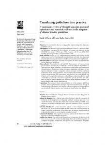
We realized a case study, using the concepts and tools described before, to prove the viability of our approach. We built the model car shown in Figure 4 and implemented an autonomous parking system based on several distance sensors on this platform. Additionally, the system is controllable manually via Bluetooth connection to a cell phone. Furthermore, it should initiate an emergency stop when reaching a given minimum distance to obstacles. R The model car is equipped with three Gumstix micro computers connected through an Ethernet network. The previously mentioned middleware is employed for data exchange and clock synchronization services. Distances are measured using two infrared and one ultrasonic sensor. Bluetooth is used as another input, connected to the cellular phone. As actuators we have the model car’s motor and steering, as well as indicator, reversing, and breaking lights.
We specified the desired system using the proposed architectural levels from FA over LA to TA and were able to generate code for the specified software components as well as the middleware configuration files. The according COLA model consisted of 37 automata and 225 networks. These elements were then partitioned into 11 distributable clusters. Our code generator transformed the model into 14 C code files with a total of 6089 LOC, and the configuration file for our middleware. After cross-compilation of the code, the system behaved correctly without the need of any manual changes.
Figure 3. Front-end of the integrated COLA engineering tool
RearLi ght i ngSyst em
Mi cr oComput er s
Fr ontLi ght i ngSyst em
Mot or /St eer i ngCont r ol
I nf r ar edSensor s
Ul t r asoni cSensor
Figure 4. Model car used in the case study on a scale 1:10
5
Related Work
During the last years both academic and industrial research and development projects were engaged in model-based development for safety-critical embedded systems. Yet, there is no fully integrated tool which covers the complete development process. Such a process should start with requirements specification in a formal way, proceed with the behavioral system design phase, and finally result in an automatically deployed and configured product. After relating the concept presented in this paper to commercial off-the-shelf products, we proceed to comment on projects from academia. Of course, there are tools for each of the mentioned phases. IBM’s Rational DOORS, and Reqtify from Geensys are widely used requirement specification and management tools. MATLAB/Simulink/Statechart from The MathWorks, SCADE by Esterel Technologies which is based on the synchronous data-flow language Lustre, and ASCET-SD from ETAS cover system and software design. Finally, for target code generation, e. g., the Real-Time Workshop Embedded Coder from The MathWorks or the KCG code generator by Esterel Technologis are employed. The mentioned tools have varying levels of integration: those of the same vendor are highly integrated, those from different vendors have an integration which is often restricted to synchronization mechanisms or rely on third party adapters like OmniLink by Omniteam. For the latter, neither an integrated data model is used nor a 100% data compatibility is guaranteed. The EU project DECOS [21] is similar to the presented approach in a way that they aim also at the development of dependable embedded systems. They present a tool-chain of more or less integrated existing tools like SCADE for behavioral modeling as well as TTPlan and TTPbuild by the TTTech Computertechnik AG for configuration and scheduling. Neither a central repository to store all artifacts created during the development process nor a formalization of requirements in the early development phase are considered. Similar to the our work, do Nascimento et al. propose to separate specification of platform independent (PIM) (comparable to our LA) and platform specific (PSM) (comparable to our TA) models, however using different metamodels [22].
Currently, they solely support UML for behavioral modeling which—according to Broy [2]—does not cater for the specific needs of the domains of embedded systems design, e.g., in the automotive industry. The Systems Modeling Language (SysML) [23] tries to overcome this limitation, by restricting UML to only essential language constructs. In return, it adds for instance requirement diagrams to efficiently capture, e. g., functional requirements. The UML2 Profile for Modeling and Analysis of Real-Time and Embedded systems (MARTE) [24], which is currently being standardized, enriches UML by concepts to support the development of real-time embedded systems. It captures aspects like hardware and software modeling as well as schedulability and performance analysis. In [25], the authors present a layered approach to implement MATLAB/Simulink models via a translation to SCADE/Lustre on the distributed time-triggered platform TTA [26]. This work completely ignores formalization and management of requirements, thus lacking support during early design phases and the possibility of automated reasoning about the designed models.
6
Conclusion
We have outlined and implemented an integrated modeling process that makes specification as well as implementation of embedded systems a controllable business. The procedural manner suggested here convinces with its agility as well as efficiency, that we believe to be beyond what can be achieved by applying a high level of automation only. The prerequisite for doing so is a well-defined formal integrated modeling language that covers all process steps. It empowers the developer to implicitly derive a mathematical representation of the modeled artifacts as a designated side effect. Several design problems can then be solved automatically by utilizing computational support. We were already able to prove the stated benefits, using our integrated modeling tool during the realization of the described case study.
References 1. Schulz, S., Rozenblit, J.W., Buchenrieder, K.: Multilevel testing for design verification of embedded systems. IEEE Design & Test of Computers 19(2) (2002) 60–69 2. Broy, M.: Automotive software and systems engineering (panel). In: MEMOCODE. (2005) 143–149 3. Arthur, S., Breed, H.N., Schmitt-Luehmann, C.: Shifting car makeup shakes up OEM status quo: Software strength is critical. IBM White Paper, last access: 2009-07-13. http://www.ibm.com/services/in/igs/pdf/ g510-1692-00-shifting-car-makeup-shakes-up-oem-status-quo.pdf (2003) 4. Broy, M., Feilkas, M., Herrmannsdoerfer, M., Merenda, S., Ratiu, D.: Seamless model-based development: From isolated tools to integrated model engineering environments. Proceedings of the IEEE 98(4) (2010) 526 – 545 5. Kang, K.C., Cohen, S.G., Hess, J.A., Novak, W.E., Peterson, A.S.: Feature-oriented domain analysis (FODA) feasibility study. Technical report, Software Engineering Institute, Carnegie Mellon University (1990)
6. Halbwachs, N., Caspi, P., Raymond, P., Pilaud, D.: The synchronous data-flow programming language LUSTRE. Proceedings of the IEEE 79(9) (1991) 1305– 1320 7. Pretschner, A., Broy, M., Kr¨ uger, I.H., Stauner, T.: Software engineering for automotive systems: A roadmap. In: FOSE. (2007) 55–71 8. Broy, M., Feilkas, M., Gr¨ unbauer, J., Gruler, A., Harhurin, A., Hartmann, J., Penzenstadler, B., Sch¨ atz, B., Wild, D.: Umfassendes Architekturmodell f¨ ur das Engineering eingebetteter Software-intensiver Systeme. Technical Report TUMI0816, Technische Universit¨ at M¨ unchen (2008) 9. Kugele, S., Tautschnig, M., Bauer, A., Schallhart, C., Merenda, S., Haberl, W., K¨ uhnel, C., M¨ uller, F., Wang, Z., Wild, D., Rittmann, S., Wechs, M.: COLA – The component language. Technical Report TUM-I0714, Technische Universit¨ at M¨ unchen (2007) 10. Rittmann, S.: A methodology for modeling usage behavior of multi-functional systems. PhD thesis, Technische Universit¨ at M¨ unchen (2008) 11. K¨ uhnel, C., Bauer, A., Tautschnig, M.: Compatibility and reuse in componentbased systems via type and unit inference. In: SEAA. (2007) 101–108 12. Bauer, A., Leucker, M., Streit, J.: SALT—structured assertion language for temporal logic. In: ICFEM. (2006) 757–775 13. Herrmannsdoerfer, M., Haberl, W., Baumgarten, U.: Model-level simulation for COLA. In: MISE. (2009) 38–43 14. Haberl, W., Tautschnig, M., Baumgarten, U.: From COLA Models to Distributed Embedded Systems Code. IAENG International Journal of Computer Science 35(3) (2008) 427–437 15. Tretmans, J., Brinksma, E.: TorX: Automated model-based testing. In: First European Conference on Model-Driven Software Engineering. (2003) 16. Haberl, W., Birke, J., Baumgarten, U.: A Middleware for Model-Based Embedded Systems. In: ESA. (2008) 253–259 17. Wang, Z., Sanchez, A., Herkersdorf, A.: Scisim: a software performance estimation framework using source code instrumentation. In: WOSP. (2008) 33–42 18. Kugele, S., Haberl, W., Tautschnig, M., Wechs, M.: Optimizing automatic deployment using non-functional requirement annotations. In: ISoLA. (2008) 400–414 19. Kugele, S., Haberl, W.: Mapping Data-Flow Dependencies onto Distributed Embedded Systems. In: SERP. (2008) 272–278 20. Haberl, W., Kugele, S., Baumgarten, U.: Reliable operating modes for distributed embedded systems. In: MOMPES. (2009) 11–21 21. Herzner, W., Schlick, R., Schlager, M., Leiner, B., Huber, B., Balogh, A., Csertan, G., LeGuennec, A., LeSergent, T., Suri, N., Islam, S.: Model-based development of distributed embedded real-time systems with the decos tool-chain. In: SAE Aerotech. (2007) 22. do Nascimento, F.A.M., Oliveira, M.F.S., Wagner, F.R.: Modes: Embedded systems design methodology and tools based on mde. In: MOMPES. (2007) 67–76 23. Object Management Group: Systems Modeling Language (SysML). OMG document: v1.1-08-11-01.pdf (2008) 24. Object Management Group: UML profile for modeling and analysis of real-time and embedded systems (marte), beta 2. OMG document: ptc/08-06-07 (2008) 25. Caspi, P., Curic, A., Maignan, A., Sofronis, C., Tripakis, S., Niebert, P.: From simulink to SCADE/lustre to TTA: a layered approach for distributed embedded applications. In: LCTES. (2003) 153–162 26. Kopetz, H.: Real-Time Systems: Design Principles for Distributed Embedded Applications. Kluwer (1997)