has applications in the internet of things (IoT) such as machine to machine (M2M) .... similar to that used in automotive remote keyless systems. (RKSs) [10].
Secure Communication Interface Design for IoT Applications, Using the GSM Network Andrew Wightwick and Basel Halak School of Electronics and Computer Science Faculty of Physical Sciences and Engineering University of Southampton, Southampton SO17 1BJ, United Kingdom
Abstract—In this work, a secure short messaging service (SMS)-based communication interface is designed. The interface has applications in the internet of things (IoT) such as machine to machine (M2M) communications, and human-operated remote system management. The case study of waking a personal computer remotely is considered, and a complete proof-of-concept is implemented for this purpose, using a field-programmable gate array (FPGA)-based receiving device and an Android-based transmitting device. On the Android device, SMS messages are generated in software using a “rolling code” system based on linear feedback shift registers (LFSRs), then encrypted with the extended tiny encryption algorithm (XTEA) cipher. The FPGA employs both hardware XTEA decryption, and hardware systems to validate incoming messages. Index Terms—decryption, encryption, FPGA, GSM, IoT, security
I. I NTRODUCTION The internet of things (IoT) is growing, due to the increasing need to share information. Many IoT communications contain sensitive information, which must be kept secure. For example, IoT home security devices could allow unauthorised access to a home if their communications were compromised. The security of internet communications has been widely studied, and established protocols such as transport layer security (TLS) can provide a secure connection. Wired internet infrastructure is however lacking in some parts of the world; the cellular network covers a greater area. It is mandatory for 3G and 4G cellular networks to provide internet access, but there is no such requirement for the older 2G standard, known as global system for mobile communications (GSM). The A5/1 cipher used by most GSM base transceiver stations (BTSs) has been broken [1], so additional security should be added to the channel if GSM communications are to be used for IoT purposes. This paper presents a generic interface design for secure unidirectional communications over the GSM network’s short messaging service (SMS). The interface has applications in various IoT use cases including machine to machine (M2M) communications, and human-controlled remote system management. All security features are implemented on the endpoint devices, so that existing GSM network infrastructure can be used unmodified. The interface provides encryption, and a “rolling code” system to provide resistance to replay attacks. A proof-of-concept implementation is presented for the case study of remotely waking a computer. This implementation
demonstrates communication between an Android smartphone and a field-programmable gate array (FPGA)-based receiver. This paper considers existing work on IoT security, and GSM-based IoT interfaces. An architecture for a secure GSMbased IoT interface is then proposed, followed by the proofof-concept implementation and an evaluation of the interface. II. R ELATED W ORK A large amount of research has been conducted on the security of IoT solutions which communicate over the internet, but not those which communicate over the GSM network. Bergstrom et al. [2] presented a solution for secure external access to a group of networked home devices, using a secure website hosted by a local server. Li et al. [3] proposed a set of internet security protocols for secure communication from smartphones to smart grids and smart homes. Mantoro et al. [4] presented a method for secure pairing a of smartphone to a smart home using Bluetooth. Kafle et al. [5] specified amendments to future cellular network infrastructure to allow IoT device authenticity to be established independently of location. Solutions have been published for IoT communications over existing GSM infrastructure, but there is scope to improve the security of these implementations. Chinchansure and Kulkarni [6] presented an FPGA-based solution, with no security beyond that provided by the GSM network. Felix and Raglend [7] used a microcontroller to forward SMS automation requests over a local ZigBee network, with a phone number whitelist to ensure sender authenticity. Baig et al. [8] proposed a similar GSM-controlled ZigBee network, extended with local control via Bluetooth. ElKamchouchi and ElShafee [9] specified a home automation system requiring incoming SMS messages to contain a plaintext password for the requested action to be performed. III. S YSTEM A RCHITECTURE A. Design Rationale The interface is designed to transmit a coded SMS message from a transmitting device to a receiving device. The authenticity of the message can be validated by the receiving device, and the message can be interpreted as a request to perform a simple action (e.g., toggling a switch). Unidirectional communication is adopted, so that only one of the two devices needs to be capable of transmitting SMS
Increment
SMS message transmission
Received
Two-wire UART uCLK
/
Ready
Data
Data
/
Ready
/
Decryption
Ready
uCLK
Rolling code validation
Increment
Clock for UART baud
Clock for WDT
wCLK
Received
Watchdog timer
Fig. 2. Block diagram showing simplified receiving device structure. Yellow blocks are externally sourced IP, and pink blocks are hardware external to the receiver’s controller
cryptographically secure random number generator. The key is then displayed on the transmitting device, for the user to input it into the receiving device manually (see green text in Fig. 3). At this point, both devices have the same cryptographic key, allowing the receiver to synchronise rolling code systems with transmitter, and interpret future SMS messages.
Wait for transmission request
Randomise cryptographic key
Randomise LFSR state
Clock LFSR
Store cryptographic key
Encrypt
Encrypt
Display cryptographic key
Transmit over SMS
Transmit over SMS
Wait to receive SMS
Wait to receive SMS
Decrypt
Decrypt
Initialise LFSR to received value
Clock LFSR
Watchdog timer Wait to receive key via switches
Receiver initialisation
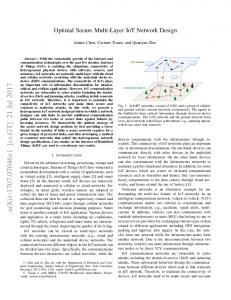
Fig. 1. Block diagram showing simplified transmitting device structure. Yellow blocks are externally sourced
The receiving device has an integrated circuit (IC)-based controller. A third-party modem is used to connect to the GSM network. The modem is interfaced over universal asynchronous receiver/transmitter (UART), because modems with this interface are widely available. The structure of receiving device is specified in Fig. 2. Rolling code validation is performed by rapidly clocking a 1024-bit LFSR, and comparing its value with the received data. The starting position of the window of valid codes is incremented whenever the watchdog timer expires, and whenever a valid message is received. A state machine within the “Controller (initialisation and parsing)” block schedules the system, and controls the UART IP block. The interface is asynchronous: the receiving device waits for an incoming SMS message before acting. The operation of the transmitting and receiving devices is shown in Fig. 3. The encryption and decryption processes are symmetric, and must be performed on different devices. This means the transmitting and receiving devices must be initialised with the same cryptographic key. For convenience, the key is automatically generated on the transmitting device using a
Controller (initialisation and parsing)
Store cryptographic key
No
Yes
Still within valid window? No
LFSR value matches received value?
Transmitter rolling codes
Encryption
Wake Data
Secure wireless link
Rolling code generation
TX
Receiver rolling codes
The transmitting device has a relatively simple structure. It contains intellectual property (IP) blocks for generation, encryption and transmission of the SMS message (see Fig. 1). The rolling code generation block consists of a 1024-bit LFSR, which is clocked both whenever the watchdog timer expires, and whenever an SMS message is transmitted.
RX
Requested action
/
Secure wireless link
B. Operation Principle
Power management
GSM modem
Transmitter initialisation
messages. This minimises the operating cost of the system: a prepaid SIM card can be used in the receiving device to allow it to operate free of charge. Messages are encrypted to enhance the security of the interface. Symmetric cryptography is used, because this is a single-user system. The key is randomly generated by the transmitting device. If an attacker intercepts and replays a message, this has the potential to fool the receiving device into performing an action. To prevent such replay attacks, the message will be changed each time it is transmitted, using a “rolling code” system similar to that used in automotive remote keyless systems (RKSs) [10]. Intercepted messages are also invalidated after a short period, by synchronised watchdog timers in both the transmitting and receiving devices. The rolling code system is based on the use of synchronised linear feedback shift registers (LFSRs) in both devices.
Yes
Perform requested action
Fig. 3. Flow diagram showing simplified operation of the complete interface. Pairing process shown with green text
Note that automated code expiry is omitted from Fig. 3 for simplicity. Automated code expiry is provided by watchdog timers with an identical period of 10 seconds, in the transmitter and receiver (Figs. 1 and 2 respectively). The validity window of the rolling code system is 3155693, meaning a code 3155692 places ahead of the current code will be considered valid. This gives a code expiration time of
3155693 · 10 seconds ≈ 1 year, after which re-pairing will be required. IV. C ASE S TUDY I MPLEMENTATION : R EMOTELY WAKING A C OMPUTER For this proof of concept, the transmitter is implemented as an Android app, and the receiver is implemented on a Digilent Nexys 4 FPGA development board (see Fig. 4).
The extended tiny encryption algorithm (XTEA) cipher [13] is chosen for the low power and simplicity of its implementation, which give a low cost. The cipher has published weaknesses [14]; the modular design of the interface (see Figs. 1 and 2) makes it easy to change the cryptosystem used, which would be desirable in a production system. XTEA is a 64-bit block cipher, based on the Feistel structure. It uses a 128-bit key, and 64 rounds. V. E VALUATION
Fig. 4. FPGA-based receiving device
All IP used in the FPGA is custom-written in SystemVerilog, apart from the decryption module which is sourced from a third party [11]. The GSM module used is a MikroElektronika GSM2 Click. The Android app is controlled by the user, using a single button to remotely wake the computer (see Fig. 5b). The cryptography IP used in the app is sourced from a third party [12].
(a) During pairing
(b) Immediately after pairing
Fig. 5. Android app GUI
The case study implementation uses an FPGA as a controller in the receiving device, to minimise the cost of prototyping. An application-specific integrated circuit (ASIC) controller would be preferred, to minimise power consumption. An ASIC could be synthesised using similar hardware description language (HDL) code to the FPGA. A development board was used for the receiving device; in a production implementation, a peripheral component interconnect express (PCIe)-based expansion card could be used for simple retrofitting to desktop and laptop computers. Testing was performed on the complete interface (transmitter and receiver), to ensure its correct operation. To ensure compatibility between the cryptography in the two devices, the same plaintext test strings were encrypted on both devices and verified to produce the same ciphertext for the same key. To check that the SMS transmission was functioning as expected, incoming signals to the FPGA receiver were captured using a logic analyser. These signals were then emulated during simulations of the FPGA receiver. Normal operation of the finished system was tested with several valid and invalid message transmissions. The receiving device was shown to be able to determine a message’s validity reliably - the electrical signal to wake the computer was produced upon receipt of valid SMS messages only. A. Security The interface’s resistance to various types of attack is evaluated below. 1) Reproducing the Initial State: Even with complete knowledge of the system’s specification, an attacker cannot reproduce its initial state. The transmitter initialises to an unpredictable random state, implemented for the case study using the SecureRandom Android class. This makes it difficult for an attacker to generate a valid message independently of the authentic transmitter. 2) Replay Attacks: It should be assumed that messages can be intercepted then replayed by an attacker. The rolling code system changes the message each time it is transmitted, and invalidates previous messages. This means replayed messages will be considered invalid by the receiving device if the original message reaches the device first. If the original message is blocked from reaching the receiving device, the system’s time-based code expiry will cause the intercepted message to invalidate after a single watchdog timer period. This means the validity of an intercepted message is limited to a single 10 s timer period.
3) Prediction of Valid Messages: Rolling code systems rely on the fact that the transmitting and receiving devices are able to predict the next valid message independently of each other. This means that consecutive messages intercepted by an attacker can be used to deduce the message sequence, then generate further valid messages. All transmitted messages are encrypted to prevent this. 4) Cryptanalysis: Third-party IP was used for XTEA cryptography. A custom-written implementation could have introduced new bugs. XTEA has known weaknesses [14], so a different cryptographic algorithm should be adopted in a production implementation. The modular design of the system makes it easy to switch to a different algorithm (see Figs. 1 and 2). 5) Brute Force: XTEA uses a 128-bit key, which requires a large number of random guesses to discover. However the case study implementation only uses 16 bits of key entropy, to allow convenient key entry using the switches built into the Nexys 4 board. In a production implementation, a longer key should be used. VI. C ONCLUSIONS Security is important in IoT applications. The GSM network provides coverage over a large proportion of the world, making it useful for expansion of the IoT. The GSM network is however vulnerable to interception, due to weaknesses in the A5/1 cipher that it uses [1]. This work presents a secure interface for communications over the GSM network, under the assumption that the communications can be intercepted. The case study implementation works for remotely waking a computer, but the interface has many further applications. The receiving device could be used unmodified in place of switches on other devices, to perform other automation tasks. As currently specified, the interface does not transmit any data apart from the validity of a message. It could be expanded to transmit additional data, such as an instruction to specify which action for the receiving device to perform. Alternatively, the receiver could act as a remote management hub, and share a single SMS interface between a collection of local devices. The interface could also be extended to allow bidirectional communication with the same rolling code system. This could be used to monitor a remote receiving device over the secure interface. A disadvantage of this approach is that the receiving device would incur an ongoing cost to send SMS messages. Beside human-controlled home automation, such as remotely waking a computer, the interface developed here has applications in M2M communication. The interface could be used to communicate with devices in remote locations, where there is no internet infrastructure. This would expand the IoT where not previously possible. R EFERENCES [1] Timo Gendrullis, Martin Novotn´y, Andy Rupp, “A real-world attack breaking A5/1 within hours,” Cryptographic Hardware and Embedded Systems CHES 2008, pp. 266–282, 2008. [2] P. Bergstrom, K. Driscoll, and J. Kimball, “Making home automation communications secure,” Computer, vol. 34, no. 10, pp. 50–56, Oct 2001.
[3] T. Li, J. Ren, and X. Tang, “Secure wireless monitoring and control systems for smart grid and smart home,” IEEE Wireless Communications, vol. 19, no. 3, pp. 66–73, June 2012. [4] T. Mantoro, M. A. M. Adnan, and M. A. Ayu, “Secured communication between mobile devices and smart home appliances,” in Advanced Computer Science Applications and Technologies (ACSAT), 2013 International Conference on, Dec 2013, pp. 429–434. [5] V. P. Kafle, Y. Fukushima, and H. Harai, “ID-based communication for realizing IoT and M2M in future heterogeneous mobile networks,” in Recent Advances in Internet of Things (RIoT), 2015 International Conference on, April 2015, pp. 1–6. [6] P. S. Chinchansure and C. V. Kulkarni, “Home automation system based on FPGA and GSM,” in Computer Communication and Informatics (ICCCI), 2014 International Conference on, Jan 2014, pp. 1–5. [7] C. Felix and I. J. Raglend, “Home automation using GSM,” in Signal Processing, Communication, Computing and Networking Technologies (ICSCCN), 2011 International Conference on, July 2011, pp. 15–19. [8] M. Q. Baig, J. Maqsood, M. H. B. T. Alvi, and T. A. Khan, “A comparative analysis on home automation techniques,” in Artificial Intelligence, Modelling and Simulation (AIMS), 2014 2nd International Conference on, Nov 2014, pp. 109–114. [9] H. ElKamchouchi and A. ElShafee, “Design and prototype implementation of SMS based home automation system,” in Electronics Design, Systems and Applications (ICEDSA), 2012 IEEE International Conference on, Nov 2012, pp. 162–167. [10] B. Davis and R. DeLong, “Combined remote key control and immobilization system for vehicle security,” in Power Electronics in Transportation, 1996., IEEE, Oct 1996, pp. 125–132. [11] D. Johnson and D. Boudreau. (2010, July) XTEA crypto core :: overview :: opencores. [Online]. Available: http://opencores.org/project,xtea [Accessed: 21/04/2016] [12] Thomas Dixon. (2005, December) The tiny encryption algorithm. [Online]. Available: http://143.53.36.235:8080/XTEA%5fjava%5ftd.txt [Accessed: 21/04/2016] [13] R. M. Needham and D. J. Wheeler, “TEA extensions,” University of Cambridge, Tech. Rep., October 1997. [Online]. Available: http://www.cix.co.uk/ klockstone/xtea.pdf [14] J. Lu, “Related-key rectangle attack on 36 rounds of the XTEA block cipher,” International Journal of Information Security, vol. 8, no. 1, pp. 1–11, 2008. [Online]. Available: http://dx.doi.org/10.1007/s10207008-0059-9