Nov 2, 2007 - In this paper we propose a new Web Services (WS) framework for managing and ... executed. We call this a Virtual Hosting Environment (VHE).
Secure Web Service Federation Management using TPM Virtualisation 1
Srijith K. Nair1*†, Ivan Djordjevic2*, Bruno Crispo1,3, Theo Dimitrakos2 Department of Computer Science, Vrije Universiteit, Amsterdam, The Netherlands 2 SOA Security, Security Research Centre, British Telecommunications, UK 3 DIT, University of Trento, Italy
{srijith, crispo}@few.vu.nl, {ivan.djordjevic, theo.dimitrakos}@bt.com ABSTRACT Web Services and SOA provide interoperability and architectural baseline for flexible and dynamic cross-enterprise collaborations, where execution and use of the participating services contributes to the common objective. Relationships within these collaborations are complex, with services joining and leaving throughout the life cycle, or the same services being offered in several collaborations simultaneously. This provides strong requirements for federated security, where integrity and confidentiality of the collaboration must be maintained through membership control, security policy enforcement and separation of web service instance interactions in different collaborations. In this paper we propose a new Web Services (WS) framework for managing and controlling WS interactions in a federated environment, leveraging on platform virtualisation architecture and the functionalities provided by trusted secure hardware. The framework allows configuring policies that define collaboration membership, and enforce access to the collaboration per-WS instance. In addition, since the access to the configurations is restricted, it provides master-slave model where only authorised administrative entity can modify any of the above - either at the deployment or at the execution time. Some of the benefits of the proposed approach are: fine-grained external exposure of WSs, a flexible model for group membership control and revocation and hardware-enabled secure virtualised system providing functional process isolation and strong data security.
Categories and Subject Descriptors K.6.5 [Management of Computing and Information Systems]: Security and Protection
General Terms _______________________________________ 1 Editing authors † Work carried out during the author’s scientific visit at BT Security Research Centre. Permission to make digital or hard copies of all or part of this work for personal or classroom use is granted without fee provided that copies are not made or distributed for profit or commercial advantage and that copies bear this notice and the full citation on the first page. To copy otherwise, or republish, to post on servers or to redistribute to lists, requires prior specific permission and/or a fee. SWS’07, November 2, 2007, Alexandria, Virginia, USA. Copyright 2007 ACM 1-59593-546-0/07/0011...$5.00.
Security, Design
Keywords Web Services, Security, Federation, Membership Management, Trusted Computing
1. 1.1
INTRODUCTION Background
With the adoption of Service Oriented Architectures (SOA), the advantages of service virtualisation are becoming prominent. It describes an advanced way of cross-enterprise integration of application services and virtualisation of the (cross-organisational) computational environment where these services are hosted and executed. We call this a Virtual Hosting Environment (VHE). VHE refers to the federation of a set of distributed hosting environments for execution of an application and the possibility to provide a single (logical) access point to this set of federated hosting environments. In addition to the application services, this virtualised service bundle needs to include a number of infrastructure services (potentially provided by a third party) for managing non-functional aspects of the application. From the perspective of a VHE consumer, the latter are transparent. VHE as such requires two main security services − trust federation and security enforcement. The basic federation model [1] assumes the existence of separate domains (trust realms) which can be identified by a common internal policy and a security administrator who controls the domain membership by issuing/revoking tokens to the entities that live inside the domain. The domain tokens (which can be seen as a WS equivalent of public-key certificates) are typically derived from the root token owned by the administrator. The administrator also handles the service of the Security Token Service (STS) for issuing and validating internal and external tokens. A crucial entity within each domain is the Policy enforcement point (PEP) which functions as the first access point for any crossdomain interactions. As described in [6], the PEP intercepts the messages entering or leaving the domain and processes them by invoking the appropriate handlers to deal with corresponding parts of the message. The policy that governs PEP behaviour, including the implementation of the handlers as well as what actions execution each of them entails, is defined by the administrative management service and can be updated at runtime.
This can include processing of various SOAP message headers such as address, signature, and so on, but also redirecting them to the STS for the evaluation of the token validity3. When several domains wish to federate, the administrators agree on this and exchange their own tokens, which subsequently allow them to validate and control any cross-enterprise interactions via PEP interceptions. However, this basic model does not allow for fine-grained separation of different collaborations. There may be one STS for the domain, and establishing trust between all of them provides the baseline for validating subsequent crossdomain interactions. However, the same service can be offered in several different collaborations at the same time. This requires an additional mechanism that allows one to separate the interactions of the same service within these collaborations. To address this issue we build on WS-Coordination [31], which uses a common “context” (an XML element) to identify the common activity, and defines Coordinator entities that are able (by creating and propagating common contexts) to correlate actions of different services into a common activity, and likewise – to distinguish actions of the same service across different activities. As described in [2], the STS is extended with the Coordinator capability and the “context” is used as a collaboration identifier which is included in the tokens created by the STS for members of a particular collaboration. The model, summarized in Section 2, still leaves the adaptation of the membership as the collaboration evolves, particularly the revocation of the removed members, as an open challenge. Web Services Definition Language (WSDL) [32], along with Web Services Resource Framework (WSRF) [33] can be used to provide a common description of the application functionalities as a web service and then to offer it as multiple instances that would maintain independent execution state even though they may refer to the same application code. This however may not be always desirable due to security reasons; for example, in a grid-like environment, where different application services may be hosted on a single execution environment, and each of the services may have many running instances that contribute to different collaborations. In addition to the flexible federation model that allows bringing together relevant service instances into a common collaboration, the full separation of the application logic and instances’ execution is a strong security requirement.
1.2
Contribution
The main contribution of the paper is a new secure framework that provides mechanisms to control membership of web service instances and the associated policies of their behaviour in a federated collaboration. We also propose a secure hardware based design of the architecture which combines security features defined at different level of abstraction, from hardware to application level, strengthening the security of the overall collaborative environment.
3
The model we refer to is implemented using WS technologies. The STS implements WS-Trust and WS-Security [30],[29]. The PEP model has some similarities to Apache Axis, for the full overview of the functionalities and architecture see [6].
By leveraging on the use of secure trusted computing technology [3], the work reported in this paper extends the existing work on the system and protocols for secure and automated cross-realm interactions of web services [2] by improving the security of the distributed web services transactions and addressing the issues of controlling admission and revocation of a participant to/from the group. The proposed architecture achieves the following: • Supports stronger forms of group membership authentication in a federated environment. • Provides a baseline for an effective master-slave relationship between trust authorities and the SOA enforcement infrastructure that facilitates security token/certificate revocation and re-issuing. • Separation of security token management and collaboration membership from the application logic. • Provides all these functionalities while making minimal assumptions on the WS environment and applying no major restrictions on the deployment topology or on the nature of the collaboration participants and their relationships. The only underlying assumption is that, within a trust realm, there is an existing trust relationship between the hardware components. The rest of the paper is organized as follows. Section 2 describes a WS-based mechanism that allows participants provided by different enterprises to engage in the common federation. Section 3 summarizes the architecture that provides separation of the management and application logic of the web services (instances). A hardware-based mechanism to control membership of web service instances and the associated policies of their behaviour in a federated collaboration is presented in Section 4. Section 5 discusses state of the art of the group-oriented secure communication protocols, and related work in the area of trusted hardware. We conclude in Section 6.
2. MODEL FOR WEB SERVICES FEDERATION MANAGEMENT This section provides an overview of the earlier proposed architecture [2] that provides a co-ordinated management of shared security context allowing participants (users, services, resources) provided by different enterprises to enter the common federation in order to execute a common activity. Typically, a demand for including new participants will appear during the collaboration lifetime, while existing participants may need to be dropped. While catering to the dynamic environment, the security of the collaboration also needs to be maintained: members of a federation must be able to identify one another, identify messages as coming from other members of the federation, and verify the truth of membership claims made by other parties in the federation.
2.1
Basic architecture
Building on the WS-Trust [30] and WS-Coordination [31], the system and protocol summarized here allows assigning roles to users/services of their organisation in the context of B2B collaboration. It provides a mechanism to dynamically bootstrap or exclude participants of the collaboration (i.e. group members),
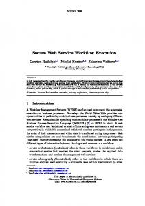
and to accordingly update security context of the group on-the-fly. The architectural model assumed is depicted in Figure 1.
Enterprise A
Enterprise B
PDP A
PDP B
Activation Registration Service A Service A
Registration Activation Service B Service B
Direct or
STS A
brokered
STS B
trust
Web Service 1
Web Service 2
Figure 1 - Secure Federation It is assumed that every entity in the model owns a cryptographic key pair and an identity token provided by the environment (i.e. a trust realm) they reside in. The token contains, among other things, the owner’s ID and public key. These tokens can be attached to every message when authenticating a requester at the destination is required. As an example, an identity token owned by web service 1 is: Tws1 = (WS1_ID, Pub_keyws1,…)signPriv_keySTS , where WS1_ID is the identifier of the service1. The Security Token Service (STS) that signs and issues these identity tokens may be different from the one which is subsequently involved in the creation of the security context. With that respect, the assumption is that there is a predefined relationship between the coordination service and the STS responsible for creating the key-pair for the group and the group token. This token is signed by a private key of that STS, and contains at least the group ID, an identifier of the service and the group public key:
Registration service of the original application or an application may use one that is specified by an interposing, trusted, coordinator. This way, an arbitrary collection of network services may coordinate their joint operation. • A coordination type-specific set of coordination protocols, which define the coordination behaviour and the messages exchanged between the coordinator and a participant playing a specific role within a coordination type.
2) Security Token Service (STS) refers to a component that can issue, validate and/or exchange security tokens, which are effectively a signed collection of claims about a particular member of a trust realm. There is at least one STS associated with a trust realm, and several entities within the same realm may use the same STS. 3) Policy Decision Point (PDP) refers to a network node that makes decisions on the basis of already defined declarative security policies. 4) Policy Enforcement Point (PEP) refers to any mechanism that enforces a (security) policy of a trust realm on a network entity. A PEP is deployed on behalf of a resource owner, service provider or user and typically will implement at least one of the following security behaviour patterns: a message inspector checks the correctness of the message including validation of any tokens expressing security claims; a message interceptor/security intermediary/gateway provides the main point where processing and transformation of message content is performed and a policy decision is enforced; A Secure message router manages secure and reliable message propagation to intermediaries and ensures that they will be able to process only the information portion/message segments that are necessary for their role, the rest of the message being made confidential.
2.3
Collaboration protocol
The collaboration among the participating entities is presented in Figure 2 and Figure 3, explaining message flow for creation and propagation of security context for the group. PDP A
Tgws1 = {GroupID, IDws1, Pub_keyg,…}signPriv_keySTS
2.2
5: authorisation request to allow WS1 to join the context
System components
Activation Service A
The following are the basic entities in the architecture: 1) Coordinator provides a mechanism for creation and automated propagation of the contextual information, which in turn can support separation of the members of different groups, and scoping of the functions/actions of the security services for the given context. It may consist of: • Activation service, with an operation that enables an application to create a coordination instance or context. Once a coordination context is acquired by an application, it is then sent by appropriate means to another application. The context contains the necessary information to register into the activity specifying the coordination behaviour that the application will follow. • Registration service, with an operation that enables an application to register for coordination protocols. The
1: request secure context
Web Service 2
9: app. message containing context & context token to “invite” new participant
2: request creation of key-pair for the context
3: return context & registration service EPR
STS A
8: context token delivery
6: authorisation response
Registration Service A
7: request context token creation for participant
4: request registration
Web Service 1
Figure 2 - Secure Federation collaboration diagram (part 1)
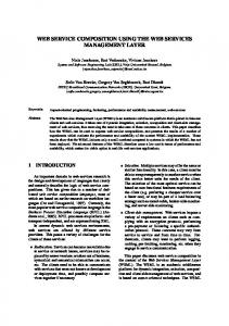
In step 1 WS1 requests group activation from the activation service A, providing its identity token for authentication purposes. In step 2 the activation service A communicates with the STS A, which creates a group key pair for this context; subsequently, this key-pair will be made available (in a form of a token and proof token) to WS1 and any other participant of the context upon successful registration (see steps 5-8 below). In step 3 the activation service A creates a group (context) identifier, and passes it to WS1, along with the address of responsible registration service A as per WS-Coordination specification. In step 4 the service WS1 requests registration with the context (i.e. participation to the group), from the registration service A. In steps 5 and 6, this request is validated and authorised at the responsible PDP for conformance with the applicable policy of the trust realm. After this is approved, the token for corresponding context for WS1 is created by STS A and delivered as shown in steps 7 and 8. In Figure 3, steps 10-14 have similar meaning as the corresponding interactions in Figure 2. Since WS2 is configured to use a different coordination service, it sends request to the activation service B, referencing both the original context and the registration service A. This will cause the original context ID to be propagated to any responsible registration service of enterprise B. There is no need for activation service B to contact the STS B at this stage (such as in step 2), since the key pair for the group already exists and will be delivered to STS B in one of the following steps. After the request is authorised (steps 13 and 14), registration service B needs to register as interposed with the registration service A (shown in step 15), which needs to be authorised against the policy of the trust realm and that of the collaboration (steps 16 and 17), including the validity of the “proof of invitation”. After this is confirmed, the registration service A requests STS A to pass the key pair to the STS B (steps 18 and 19); assuming a trust relationship already existing between the two trust realms. Confirmation is then passed back to registration service B (step 20), upon which registration service B can request STS B to issue the context token for WS2 (step 21). In step 22, this token is delivered.
PDP A 16: authorisation request to allow interposition
PDP B
17: authorisation response
13, 14: authorisation request/ response 15: request for interposition
Registration Service A
Registration Service B
20: ack
18: request key pair to be passed to STS B
STS A
21: request context token creation for participant
19: key pair delivery (existing federation assumed)
STS B
22: context token delivery
23: app. message response to WS1, secured with the context token
Activation Service B
12: request registration
10: request secure context (pass existing context) 11: return same context & new registration service EPR
Web Service 2
Figure 3 - Secure Federation collaboration diagram (part 2)
2.4
Benefits
In order to allow for this mechanism, the interacting entities need to be exposed via Web Services interfaces and need to understand WS-Trust and WS-Coordination specifications. In addition, highlevel trust relationship between STS A and STS B needs to be established in advance (preferably offline). In turn, the mechanism ensures that only participating services that receive the full group context following successful registration are able to enter the group/activity interactions and that group interactions are not visible to non-member services. The activation and registration services provide and manage lifecycle of the shared security context among a group of services in a federation of trust realms using security tokens. The local identity of the group and/or of a service is bound to the shared security context of the group and services/participants assert their membership to the group by presenting the security context. In addition, the management of security perimeter protecting the group is automated by utilising specialised infrastructure services which provide security policy, federation of trust realms, creation/ translation of security tokens and keys. Furthermore, group membership management does not require any prior knowledge, it evolves as new participants added or removed from the group. One of the existing challenges in the model is a good mechanism for removing members from the group. At present, this can be done using the protocol previously described. It is possible to configure administrative nodes (i.e. registration services) to exchange any updates on the members being removed from the group (in the form of a signed list), and to propagate that further down to the services they are responsible for. This would form the extension of the group policy, which would need to be checked for every incoming/outgoing message in order to ensure that the message is not being received from (sent to) the entity which group membership is revoked. Problem of revocation has been and still is widely studied, and a choice of a good scalable solution depends a lot on the architecture in place and security requirements. A number of models and extensions have been proposed - for both certificatebased and group-oriented architectures (for more information see [34]), and they mainly rely on the timely updates and enforcement of the group membership at the recipient side. One of the important issues that we address with this work is a scalable mechanism for membership revocation and/or privilege adaptation that does not compromise the security of the model previously described. We leverage on our previous work on virtualised trusted computing platform for web services security [4], and extend the model to provide secure and enforceable membership management and control of federated groups.
3. VIRTUALSATION AND TRUSTED COMPUTING In this paper we aim to ease secure group membership and solve the problem of membership revocation. To achieve this we propose an approach that uses the technology of platform virtualisation and secure hardware mechanisms for the key storage (i.e. trusted platform module [3]), with the software web services running on that hardware, at the time of the software deployment.
VM
Virtualisation provides us with mechanisms to create partitions that share the hardware resources but are logically isolated. By running web service instances in separate partitions, not only can their security be improved, but also the efficiency of the process distribution, by optimising the use of the hardware resources. Trusted computing provides technology for cryptographic keys and application data to be stored securely within the machine hardware and provide mechanisms to attest the integrity of a remote machine. In this section we give a brief summary of these technologies.
3.1
Virtualisation
The concept of a virtual machine was first developed by IBM in order to provide concurrent access to the mainframe resources [8]. Each virtual machine (VM) provided a completely protected and isolated abstraction of the underlying hardware architecture to the applications running inside it. In the recent years, hardware virtualization has become a popular technology since sharing of hardware among multiple workloads reduce operating costs as well as makes the system utilization more efficient [9]. The Virtual Machine Monitor (VMM) software layer provides this virtualization layer and supports the creation, maintenance and teardown of the virtual machines. Detailed explanation of these implementations are beyond the scope of this paper and interested readers are referred to [10],[11].
3.2
Trusted Computing
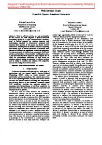
Trusted computing aims to provide cheap open commodity systems with certain desirable properties, usually associated with high-assurance closed systems. The Trusted Platform Module (TPM) specifications [3], defined by the Trusted Computing Group [13], provide a mechanism to implement such a trusted computing architecture by using (among other things), a hardware root of trust. The TPM, implemented as a chip that is attached to the motherboard of the machine, provides several cryptographic operations, such as random number generation, asymmetric and symmetric key encryption and decryption, signing, secure hashing, etc. Each TPM has several cryptographic keys built in. Storage Root Key (SRK) forms the Root of Trust for Storage and always resides in the non-volatile memory of the TPM. When a TPM generates a key, it is generated by its parent key and SRK forms the root of this tree. Endorsement Key (EK) is used to uniquely identify the TPM. Each TPM manufacturer provides a certificate to the EK attesting the compliance of the TPM to the specifications. The TPM produces Attestation Identification keys (AIKs) that are linked to the platform using certificates from the EK. Certification Authorities (CAs) uses the certificate issued by the EK and the manufacturer’s certificate of EK to attest the AIKs. Each TPM has at least 16 Platform Configuration Registers (PCRs) that store measurement values (usually hash values) of platform configurations which, along with the AIKs, can be used to attest the state of a machine using the process of remote attestation [14]. Just like any other hardware, the TPM needs to be virtualized in order to be used within a VM setup. IBM’s work on vTPMs [7] is an excellent starting point. The hardware TPM is controlled by a vTPM Manager that resides in one of the VMs, as shown in
V T P M
V T P M
V T P M
VM
Application
Application
OS with Client TPM Driver
OS with Client TPM Driver
vTPM Manager
Virtual Machine Monitor
TPM Hardware
Machine Hardware
Figure 4: vTPM Architecture Figure 4. It also creates other vTPM instances that are then associated with individual VMs. Each vTPM instance performs the full set of TCG TPM specifications, thus allowing each VM to use the vTPM instances as if the VM had a direct control over the physical TPM chip. By generating an EK per vTPM, this architecture allows each vTPM, and hence each VM that uses the instance, to decrypt information using the private key associated with the EK. It also enables the creation of independent key hierarchy per vTPM. By using the trusted computing architecture for deploying web services, one can increase the security of the system (keeping the encryption key secure in the TPM), and can also support the possible requirement of consumers, enabling them to verify the integrity of the deployed system (using remote attestation).
4. TC DERIVED WEB SERVICES ARCHITECTURE As mentioned earlier, in this paper we propose a framework that leverages on the power of platform virtualisation and secure trusted hardware to improve the security and management of group membership and membership revocation in a federated environment. As explained later on, our architecture leverages on the property of Trusted Computing that secret information owned by various entities (including WS - web service instances) can be securely stored by encrypting it with a hardware-protected key. When the entity in question possesses certain privileges, it is entitled to access this information (according to the defined policy) in order to protect its interactions. In addition, virtualisation enables the platform host to securely isolate these entities allowing for efficient platform usage while at the same time ensuring their independent existence. By providing virtualised TPM module for each VM on a host, more fine-grained control can be achieved, in terms of which user entity is authorised to access and use the WS instance, as well as which administrative entity is authorised to manage the security configurations of the WS instance. Typically, the former would correspond to the scope of the collaboration, whereas the latter would map to the stakeholder that owns the service (but may be using outsourcing for the service hosting). As a WS joins a new group or leaves existing groups, this security information can be updated via programmable means by an authorised administrative entity of the trust realm, which has
access to the management interface of the enforcement point – either locally or over a trusted network connection4. The choice here can depend on the deployment architecture of an organisational network, or on particular security requirements. Referring to the federation model presented in Section 2, a dedicated management functionality associated to the coordinator can act as a local-domain administrative entity for this purpose. In the rest of the paper we will refer to this entity as a TPM administrator. However, separation of the functionalities, as well as coordination of the activities between the coordinator and TPM administrator needs to be ensured.
4.1
Local Domain and Group Membership Token
In this subsection we introduce the protocol that has to be followed by a web service W1 in order to obtain local domain membership token T1 from TPM administrator A1 and group membership token Tg from STS1. In step 1, W1, instantiated in an isolated partition, sends a request M1 to TPM administrator A1 asking for a local domain membership token. The request contains the public part of the vTPM’s Endorsement Key (EK), the End Point addRess (EPR) of the service instance and a signature on these values using the Attestation Identity Key of the vTPM.
1: Request membership token A1 2: Challenge / Response
BSM
3: Token delivery
Optionally A1 could run a challenge-response protocol (step 2) to ensure that the advertised EPR of the WS1 does indeed exists and that it has access to the private key of vTPM’s EK. If this is verified successfully, A1 sends T1 back to W1 as shown in step 3. T1 = EKW1, EPRW1, Pub_keyA1, EPRA1, Sig{EKW1, EPRW1}A1, Sign {Pub_keyA1}TTP, other details Where EKW1 is the public part of W1’s Endorsement Key, TTP is a trusted third party like VeriSign and ‘other_details’ denotes all other required and optional details like validity time period etc. As before, the two BSM shown in the diagram could either be a single physical entity or be implemented on separate hardware. A similar protocol is run between W1 (using T1 to prove its membership) and STS1 resulting in W1 obtaining Tg`.
4.2
Membership Revocation
As pointed out earlier, membership revocation represents a significant challenge in a dynamic environment. Revoking W1’s membership of a group involves two separate steps. • Updating membership list - The STS maintains, for each group created in its domain, the list of WS instances that are members of the group. When (say) W1 leaves a group, its details are removed from the membership list and the updated list is published. This can be done without much complication by assigning a short expiry date for the membership list and getting STS to republish a signed and time-stamped version of the membership list, reflecting any additions and deletions to/from the list. This process serves mainly as an auditing mechanism to ensure and verify the accountability of STS. • Removing W1’s access to Tw1-g - When W1 leaves a group; it should no longer be able to send messages to the group. In practice this can be implemented by revoking W1’s access to the group token Tw1-g.
W1
BSM
Figure 5: Steps for obtaining local domain token The Base Service Manager (BSM) [4] is a trusted piece of software that manages the creation, maintenance and teardown of WS instances and is logically located at the same level as the type2 VMM5. The protocol above assumes that the local domain administrator and the WS instance shares the same BSM and hence is hosted on the same machine. If this is not the case, a second round of signature chain has to be added to M1 to prove the authenticity of the AIK of W1’s vTPM. W1 � A1: M1= EKW1,EPRW1,Sig{EKW1, EPRW1}AIKW1
4
Local access and trusted network connection access are not differentiated , hereafter 5 VMM runs within level 2 protection ring (OS) with guest OS running at level 3 (applications)
Preventing W1 access to Tw1-g, including physically removing Tw1from the secure storage associated with W1, may not be straightforward, depending on the threat model assumed. If the web services are trusted to adhere to their specified behaviour then removing access to Tw1-g can be achieved by introducing a management action to the management capabilities [5] of W1 that enables the TPM administrator or management agent to request, via the management interface of W1, the removal of (access to) Tw1-g. g
However, in many cases the threat model assumes that the web services are not trusted and hence are not expected to behave as specified when the group membership tokens need to be forcefully revoked. The solution we propose is to implement a scheme in which the group token is never given directly to W1, thus preventing its full control of Tw1-g. The next section examines our proposed architecture that implements such a system, by relying on hardware compliant with the trusted computing platform architecture [3].
Mo, Tw1-g1, (…)
Mo, (…)
TPM VM
PEP VM
GT?
WS VM
WS VM
GTH VM
Tw1-g1 Token List Interceptor repository v
v
v
T
T
T
P
P
P
M
M
M
W2 components W1 components A1
Tw1-g1
W1
Tw1-g2 W2 Data
W1 Data
A1 Twn-g1
TPM command flow
Wn SOAP message flow
A2
vTPM Manager
action chain + config data of WS1
An
Guest OS with
Guest OS with
Client TPM Driver
Client TPM Driver
GTH Mi
Virtual Machine Monitor + Base Service Manager TPM Hardware
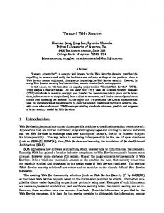
Figure 6: Modified partition architecture for WS instances
4.3
Revised Control Model Membership Tokens
for
Group
As explained earlier, in many cases it is not desirable to allow web service instances direct access its own group membership token. One possible solution which forms the basis of the architecture proposed in the paper is to introduce a new secure portioned sub-system that acts as the access handler and which controls the life-cycle of such security tokens. We call such an entity the Group Token Handler (GTH). Following the architecture from [4], the GTH can be represented as a triple (P, H, MC) where P is a dedicated partition, H is a handler, and MC is a dedicated manageability capability, i.e. a part of the manageability interface of the enforcement middleware associated with the corresponding service instance. The GTH-enabled system is implemented by extending the architecture defined in [4], as shown in the Figure 6. As before, the TPM and PEP VM are isolated into their own partitions, with each WS instance’s VM forming other partitions. In additions a VM partition is created for the GTH and its data. When the STS allows W1 membership to a group, the group token Tw1-g and the private key corresponding to the group public key present in Tw1-g is sent to the GTH, instead of to W1. When W1 wishes to send a message to the group members, it sends the message (without the group token) to the PEP. The PEP then sends the message to the GTH partition. As long as W1 is recognized as a group member by STS1, any such request on behalf of W1 to insert Tw1-g and encrypt and sign the outgoing message will be honoured by GTH. The GTH partition is configured to accept requests by specific manageability clients, including the TPM administrator and the STS. An authorisation policy that each authority in the trust realm can use MC only for the tokens that it has provided can
be used to impose restrictions on the working of these manageability clients. When either the TPM administrator A1 or the security token service STS1 wishes to revoke one of the existing group tokens, it requests the GTH to prohibit access to this token from any WS or that the token be destroyed. Similarly if a specific WS leaves a group, its access to the corresponding group token is denied by removing the token from the list of groups it is a member of. This is done using the corresponding manageability interface of the enforcement component (i.e. the MC of the PEP). On receiving this request, GTH updates the corresponding token list by making the requested token inaccessible or by destroying it. If dependencies exist between tokens, these should be reflected in the way the tokens are stored and also in the way their removal or denial of access to them is implemented. For example, according to [2], the validity of group tokens depends on the validity tokens identifying an entity within its original trust realm. Consequently the removal of identification token should imply the removal of all group tokens whereas the removal of a group token should not affect the validity and use of such an identification token. Removing or making a group token inaccessible isolates the WS from all group interactions since the group token has to be attached with every outgoing message in order to prove membership in the group [2]. At the same time, since the GTH would refuse the use of the group private key to decrypt subsequently received group messages, the confidentiality of the messages is maintained.
4.4
Alternate Architectures
The proposed architecture in Figure 6 can have several variations based on varying levels of entity isolation. Figure 6 shows the GTH being shared between various WS instances on the same VHE. By further decomposition of the managementrelated partitions, higher level of security and re-configurability can be achieved. Examples of these are illustrated below.
Policy/ GTH VM
Policy/ GTH VM Mo,T w1-g1 (…)
PEP VM TPM VM
Policy for W1
Policy for W2
W1 Token List T w1-g1, T w1-g2, …
W2 Token List Tw2-g1, T w2-g2, … GTH2
GTH1 Interceptor repository
A1
WS VM
WS VM Tw1-g1 v
v
v
T
T
T
P
P
P
M
M
M
action chain + config data of WS1
GT?
TPM command flow W1 components
W2 components
W1 Data
W2 Data
Mo, (…) A1
SOAP message flow
A2
An
vTPM Manager
Guest OS with
Guest OS with
Client TPM Driver
Client TPM Driver
Mi
Virtual Machine Monitor + Base Service Manager
TPM Hardware
Figure 7: Separation of GTH partition per WS instance Figure 7 shows a model with a separate GTH partition for each WS instance. This allows different WS instances to co-exist on the same host, whilst being used in different collaborations controlled by different administrative entities, which can independently manage their memberships. Figure 8 shows a model where, in addition to separate GTH partition for each WS instance, there is a Policy VM for each WS instance as well. While still allowing for separate membership management per instance, this model also allows the authorities of collaboration management and security policy management to be granted to different administrative entities. So, for example, while a collaboration administrator can be an entity trusted and/or jointly appointed by all collaboration participants to manage this particular collaboration, security policy administrators may be entities from the organisational domain, responsible for updating security configuration of the WS instance to reflect the access policies of each participant.
By increasing the amount of isolation between the components these alternate architectures improve on the security and integrity assurance provided by the system. Since each partition can have its own TPM, data specific to the functional partition can be encrypted using the VM specific TPM keys. Each partition can also be given a separate management interface allowing for support of finer delegation of management responsibilities. However, the larger isolation comes at the cost of scalability and management overhead. The creation and maintenance of extra VMs to hosts the individual GTHs and Policy VMs would mean that the number of WS instances that can be supported per VHE would decrease. Also, a TPM administrator would need to maintain larger set of keys, and potentially to perform more frequent invocations. A decision on which of the architectures should be adopted in practise depends on the security assurance demanded by the WS component consumers.
Policy VM
Policy VM
Policy for W1
Policy for W2
Mo,T w1-g1 (…) GTH VM
GTH VM PEP VM
Interceptor repository
v
v
T
T
W2 Token List Tw2-g1, T w2-g2, …
W1 Token List Tw1-g1, T w1-g2, …
TPM VM
Tw1-g1
v
P
P
M
M
WS VM Mo, (…)
T
P M
A1
GTH2
GTH1
action chain + config data of WS1
GT?
WS VM
W1 components
W2 components
W1 Data
W2 Data
TPM command flow
SOAP message flow
A1
A2
vTPM Manager
Mi
An
Guest OS with
Guest OS with
Client TPM Driver
Client TPM Driver
Virtual Machine Monitor + Base Service Manager
TPM Hardware
Figure 8: Further decomposition of security enforcement partitions: GTH and Policies per WS instance
4.5
Revoking the STS
So far we have considered the process of revoking the group membership of the WS when instructed by the STS. Even though the STS itself is protected by an isolated partition, a strong threat model has to assume that the STS can also be compromised and hence may in turn need to be revoked. In order to counter such a powerful attack, an additional architecture layer that uses a new entity called the STS Revoker (STSR) is proposed (Figure 9).
2: Request membership token
STS1
BSM
3: Challenge / Response 5: Token delivery
W1
4: Token insertion request
1: STS revocation message
STSR
GTH1 BSM
Figure 9: STS Revoker concept When a STS compromise is detected, the STSR informs the GTH that it should use a new STS’s service to check group membership. In order to do this, during the initialization phase of the GTH, the administrator also specifies the EPR of the STSR along with the EPR of the STS(s). When a compromised STS is detected, STSR (using out-of-band methods) informs the GTH to stop using the compromised STS and provides the GTH with the EPR of an alternate STS to use from then on. This procedure assumes that the STSR is more secure that the STS6. The overall STSR architecture is shown in Figure 9 above.
5.
RELATED WORK
Research in secure group communication aims to provide group membership control, secure key distribution, and secure data transfer [19]. Typically, this is achieved by distributing the group key only to the participants (control of the group membership), and using that key for encryption of the traffic (secrecy of exchanged data). In addition, in a dynamic environment, where members can freely join and leave, integrity of the group is preserved by refreshing the group key, while ensuring that the key distribution is done in a secure and scaleable way. A number of schemes for key management and distribution exist [20], which can be mainly divided into centralised, decentralised, and distributed. While these have their distinct advantages and shortcomings, most of the approaches are concerned with design of secure group packet-level protocols. However, there are two important issues related to the authentication and access control which are developed to the 6
STSR can be a device that is not permanently “online”, but is switched-on only for the purpose of (re)configuration only, or for responding to an identified security threat.
lesser extent, and are also more relevant to the work presented in this paper. Commonly, authentication provided with a key management is recognised as a group authentication, meaning that participating entities can authenticate each other as a group member. However, authentication on the level of an individual user is far more complex if relying on the group protocols only. For this, schemes that consider network location [21], third party –generated public-key certificates [22], or Diffie-Hellman agreement (see [18]) for distributed ad-hoc communities [23] have been considered. The second issue, of access control, is normally concerned with admission to a group, i.e. whether or not an entity is a valid member of a group [20]. This is provided through timely update and distribution of a group key. However, this does not provide any means of constraining actions of an entity once it is allocated to a group, or for defining more finegrained group policy other than inclusion/exclusion. Various authorisation frameworks and mechanisms have been proposed [1][24][25][26][27][28][29]. This is the area of active research, particularly when there is a requirement for group members to reside in different administrative domains. On the other hand, several recent research works have been investigating on how virtualization can be extended to support the ‘on demand’ nature of web service hosting requirements. SODA [12] is one such architecture that virtualizes each service nodes by running it within individual VMs on the hosted machine. By designing their architecture in a Master-Agent setup they are able to create the needed services on demand, across several machines in the hosting farm. Up to date however, work in the area of virtualisation provides only basic process isolation and system security that is inherent in the virtualisation paradigm and does not extend the architecture to perform WS specific functionalities. In summary, we are not aware of any existing or similar work that tackles issues of hardware-based group-oriented security and membership management for the purpose of cross-domain web services interactions.
6.
CONCLUSION AND FUTURE WORK
In this paper we propose a new Web Services architecture that eases the burden of policy configuration in establishing dynamic secure federated collaborations and supports fine-grained enforcement at the level of WS instance. Furthermore, we extend [2],[4] and [6] by introducing an architecture that facilitates the propagation and life-cycle management of group membership state and tokens by leveraging on the use of a virtualised trusted computing platform architecture in a federated environment. The architecture uses the concept of Group Token Handler to maintain and destroy the group tokens on behalf of the web service. Furthermore by using trusted hardware, the architecture allows secure generation and storage of tokens and keys proving membership in groups within and across the trust realms of a federated environment. Depending on which of the described alternative architectures is used, further work may be needed to analyse the very details of the interaction protocols and define the exact content of the associated messages. The performance overhead introduced by the GTH needs to be analysed further, in order to confirm that the GTH does not represent the bottleneck in the implementation, as it needs to mediate all group messages related to the web service
instance. Finally, another aspect of our ongoing work is on the architectural extension, addressing the design of the [15]
Next stage in our work, covering the above aspects, is an experimental implementation of the proposed architecture in order to secure the interactions on the WS-based B2B Gateway described in [15].
ACKNOWLEDGEMNTS
[16] [17] [18]
Some aspects of the work reported in this paper are funded by EU IST integrated projects TrustCoM [16] and BEinGRID [17].
REFERENCES [1] Djordjevic I., Dimitrakos T., Romano N., Mac Randall D., Ritrovato P.: Dynamic Security Perimeters for Inter-Enterprise Service Integration. Future Generation Computer Systems, the International Journal of Grid Computing: Theory, Methods and Applications, Elsevier B.V. 2007, Volume 23, Issue 4, Pages 633657 (May 2007). URL: http://sciencedirect.com/science/journal/0167739X [2] Djordjevic I., Dimitrakos T.: A system and protocol for coordinated management of shared security context of a collection of network entities within a federation. European Patent Office (in process, PCT application No to be assigned) [3] “TCG Specification Architecture Overview”, Trusted Computing Group, Revision 1.2, April 2004, https://www.trustedcomputinggroup.org/ [4] Djordjevic I., Nair S.K., Dimitrakos T.: Virtualised Trusted Computing Platform for Adaptive Security Enforcement of Web Services Interactions. In proceedings of the International IEEE Conference on Web Services (ICWS07), July 9-13, 2007, Salt Lake City, Utah, USA [5] Sedhukin I. (editor) “Web Services Distributed Management: Management of Web Services (WSDM-MOWS) 1.0”. OASIS OASIS Web Services Distributed Management (WSDM) TC. Dec. 2004. [6] Maierhofer A., Dimitrakos T., Titkov L., Brossard, D.: Extendable and Adaptive Message-Level Security Enforcement Framework, In proceedings of the International conference on Networking and Services, (ICNS '06), Paolo Alto, July 2006, ISBN: 0-7695-2622-5 [7] “TCG Generic Server Specification”, v 1.0 revision 0.8, Trusted Computing Group, May 2005, https://trustedcomputinggroup.org/ [8] Creasy R.J.: The Origin of the VM/370 Time-Sharing System, IBM Journal of Research and Development, 25(5):483, 1981. [9] Figueiredo R., Dinda P.A., Fortes J.: Resource Virtualization Renaissance, IEEE Computer Magazine, 38(5):28-31, 2005. [10] Goldberg R.P.: Survey of Virtual Machine Research, IEEE Computer Magazine, 7(6):34-45, 1974. [11] Nanda S., Chiueh T.: A Survey of Virtualization Technologies, Research Proficiency Report, Stony Brook, ECSL-TR-179, February 2005. [12] Jiang X., Xu D.: SODA: A Service-On-Demand Architecture for Application Service Hosting Utility Platforms, In proceedings of 12th IEEE International Symposium on High Performance Distributed Computing, pp. 174, 2003. [13] Trusted Computing Group, https://trustedcomputinggroup.org/ [14] Sailer R., Zhang X., Jaeger T., van Doorn L.: Design and Implementation of a TCG-based Integrity Measurement
[19]
[20]
[21]
[22]
[23]
[24] [25]
[26]
[27]
[28]
[29] [30] [31] [32] [33] [34]
Architecture, In proceedings of the USENIX Seceurity Symposium, 2004. Dimitrakos T.: Securing application service exposure & integration in B2B collaborations. In business track of ECOWS 2006, the 4th IEEE European Conference on Web Services, Zurich, December 2006. TrustCoM project website: www.eu-trustcom.com BEinGRID project website: www.beingrid.eu Menezes A., Oorschot P.van, Vanstone S.: Handbook of Applied Cryptography. CRC Press, 1996. ISBN: 0-8493-8523-7, www.cacr.math.uwaterloo.ca/hac/ Dondeti L.R., Mukherjee S., Samal A.: Survey and Comparison of Secure Group Communication Protocols. Technical Report, University of Nebraska-Lincoln, June 1999; http://citeseer.ist.psu.edu/dondeti99survey.html Rafaeli S., Hutchison D.: A survey of key management for secure group communication. ACM Computing Surveys (CSUR), Vol.35, Issue 3, September 2003; pp. 309 . 329 Ballardie T., Crowcroft J.: Multicast-Specific Security Threats and Counter-Measures. Proc of Symposium on Network and Distributed System Security (SNDSS.95), San Diego, USA, February 1995 Agarwal D.A., Chevassut O., Thompson M.R., Tsudik G.: An Integrated Solution for Secure Group Communication in WideArea Networks. Proc of 6th IEEE Symposium on Computers and Communications, Hammamet, Tunisia, July 2001 Ateniese G., Steiner M., Tsudik G.: New Multiparty Authentication Services and Key Agreement Protocol. IEEE Journal on Selected Areas in Communications, Vol.18, No.4, April 2000; pp. 628-639 Hardjono T., Weis B.: The Multicast Group Security Architecture. RFC 3740, Category: Informational, IETF, March 2004 Chadwick D.W., Otenko A., Ball E.: Role-Based Access Control with X.509 Attribute Certificates. IEEE Internet Computing, Vol. 7, Issue 2, March/April 2003, pp. 62-69 Thompson M.R., Essiari A., Mudumbai S.: Certificate-Based Authorization Policy in a PKI Environment. ACM Transactions on Information and System Security (TISSC), Vol. 6, Issue 4, November 2003, pp. 566-588 Pearlman L., Kesselman C., Welch V., Foster I., Tuecke S.: The Community Authorization Service: Status and Future. Conference for Computing in High Energy and Nuclear Physics (CHEP03), La Jolla, California, USA, March 2003. Alfieri R. et al: Managing Dynamic User Communities in a Grid Autonomous Resources. Proc of Conference for Computing in High Energy and Nuclear Physics (CHEP03), La Jolla, California, USA, March 2003. OASIS Specifications; http://www.oasis-open.org/committees/committees.php Web Services Trust Specification, www.ibm.com/developerworks/library/specification/ws-trust/ Web Services Coordination Specification; www.ibm.com/developerworks/library/specification/ws-tx/ Web Service Definition Language (WSDL) Specification; http://www.w3.org/TR/wsdl Web Services Resource Framework; http://www.globus.org/wsrf/ Djordjevic I.: Architecture for Dynamic and Secure Group Working. PhD Thesis, University of London, London, UK, June 2004