Selective Component-based Rendering Kurt Debattista∗ University of Bristol
Veronica Sundstedt University of Bristol
Abstract The computational requirements of full global illumination rendering are such that it is still not possible to achieve high-fidelity graphics of very complex scenes in a reasonable time on a single computer. By identifying which computations are more relevant to the desired quality of the solution, selective rendering can significantly reduce rendering times. In this paper we present a novel component-based selective rendering system in which the quality of every image, and indeed every pixel, can be controlled by means of a component regular expression (crex). The crex provides a flexible mechanism for controlling which components are rendered and in which order. It can be used as a strategy for directing the light transport within a scene and also in a progressive rendering framework. Furthermore, the crex can be combined with visual perception techniques to reduce rendering computation times without compromising the perceived visual quality. By means of a psychophysical experiment we demonstrate how the crex can be successfully used in such a perceptual rendering framework. In addition, we show how the crex’s flexibility enables it to be incorporated in a predictive framework for time-constrained rendering. CR Categories: I.3.7 [Compute Graphics]: Three-Dimensional Graphics and Realism Keywords: selective rendering, time constraints, global illumination
1
Introduction
High-fidelity rendering is the process of creating physically-based synthetic images which are perceptually indistinguishable from the real scene they are depicting. Such imagery is computationally expensive to render. Highly optimised renderers [Wald et al. 2003] can achieve ray traced images of complex scenes and global illumination of moderately complex scenes in real time. For full global illumination requirements, selective rendering has been shown to be capable of achieving high quality images in reasonable times by identifying which computations are more relevant to the final solution [Yee et al. 2001; Cater et al. 2003]. In many applications, for example during an animation development process, we wish to visualise certain aspects of the lighting simulation within an appropriate time frame. To achieve this, the rendering process needs a flexible user-controlled system to facilitate the trade-off between the desired quality of the solution and the rendering time. Traditionally for high-fidelity selective rendering, flexibility is obtained by varying the number of primary rays shot. We investigate a different method, the component-based approach, where we use the property that the light that hits a surface can be divided into various components which can then be rendered individually as a basis for our flexibility, see Figure 1. In this paper we demonstrate the benefits of this approach for a number of aspects of selective rendering. Firstly, we show a rendering system with the flexibility of controlling the light transport ∗ e-mail:
[email protected]
Luis Paulo Santos Universidade do Minho
Alan Chalmers University of Bristol
rendered in an image according to a specific component regular expression, which we term a crex. Secondly, we use the crex to specify the perceptual priority of features in a scene. Finally, we use the crex within a time-constrained rendering system to determine which components can be computed within a bounded time. Currently our implementation extends the lighting simulation system Radiance [Larson and Shakespeare 1998], but this approach could equally be used in conjunction with other global illumination systems. The goal of our work is to include such a component-based selective renderer in rendering-on-demand [Debattista et al. 2005] systems and high-fidelity interactive graphics engines. The paper is organised as follows. Initially we present the related work in the fields of selective rendering and component-based rendering. Subsequently, in Section 3, we present our componentbased framework and the crex. Then, in Section 4, we demonstrate how our framework can be used to exploit attentional processes and finally, in Section 5, we show how the crex is incorporated in timeconstrained systems.
2
Previous work
Our work draws from previous research in visual attention, selective rendering and component-based rendering.
2.1
Visual attention
Two major processes determine where humans direct their visual attention [James 1890]. These processes are bottom-up, which is an automatic visual stimulus and top-down, which is voluntary and focuses on the observer’s goal. The bottom-up process has been found to be influenced by contrast, size, shape, color, brightness, orientation, edges and motion. [Koch and Ullman 1985] presented the notion of a saliency map, a two-dimensional map that encodes the saliency of objects in the environment. [Itti et al. 1998] developed a computer model to predict the saliency of objects in the scene. The top-down approach was highlighted by the visual psychologist Yarbus [Yarbus 1967]. He demonstrated the affinity of eye movements to the visual task being performed. [Cater et al. 2003] used this concept to produce task maps which are two-dimensional maps identifying the task region within a scene. Perceptual metrics such as Daly’s Visible Differences Predictor [Daly 1993] were also developed as image-space algorithms that measure the perceptual difference between two images.
2.2
Selective rendering
We use the term selective rendering to refer to algorithms that allow a choice of flexible computation within a rendering framework. Techniques applicable to selective rendering date back to early work on level of detail [Clark 1976]. More recent level of detail work for real-time applications is summarised in [Luebke et al. 2002]. [Bergman et al. 1986] adaptively refined images, progressively improving the display quality from wire-frame to better shaders (flat, Phong, Gouraud) and improving anti-aliasing. With regards to global illumination, progressive radiosity could be
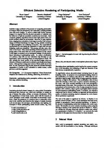
Figure 1: The Cornell box scene split into a number of Radiance shader-specific components: (top-left) direct, (top-middle) indirect diffuse, (top-right) pure specular, (bottom-left) specular for mirror shader, (bottom-middle) transmitted for glass shader, (bottom-right) reflected for glass shader (including transmitted) and (right) the full solution.
viewed as a selective rendering solution [Cohen et al. 1988] to providing a faster converging and interruptible solution to the classical radiosity algorithm. Similarly, Painter and Sloan’s adaptive progressive refinement ray tracer [Painter and Sloan 1989] is a progressive formulation of the classical ray tracing algorithm. [Chen et al. 1991] presented a progressive refinement algorithm for a multipass rendering algorithm combining progressive radiosity, ray tracing and backwards ray tracing, where the individual passes were interruptible. Although techniques based on those outlined in Section 2.1, had been developed before, such as [Mitchell 1987] adaptive antialiasing sampling for ray tracing, they have become more popular recently. [Prikryl and Purgathofer 1999] provide an overview of perceptually-driven rendering radiosity algorithms. [Myszkowski 1998] and [Bolin and Meyer 1998] used visual difference predictors both to direct the next set of samples within a stochastic ray tracing framework and as a stopping condition. The main drawback of these approaches is the expensive computation of the visual difference predictors performed many times within the calculation of a single image. [Ramasubramanian et al. 1999] decoupled the spatially-dependent saliency component from the luminancedependent component. By pre-computing the former, they improved performance substantially for their path tracer. [Yee et al. 2001] exploited a saliency model they termed the Aleph Map to influence the search radius accuracy of the interpolation of irradiance cache values for the indirect diffuse component of the calculation. [Haber et al. 2001] in their real-time renderer use saliency maps and the notion of task objects to identify the most salient objects for which to render the glossy and specular components. In [Cater et al. 2003; Sundstedt et al. 2004] both task maps and saliency maps are used to vary a number of rays shot per pixel in a global illumination environment. [O’Sullivan et al. 2004] presented an overview of recent work in perceptually adaptive graphics.
2.3
Time-constrained rendering
One particular aspect of selective rendering, involves rendering with the highest quality possible within a given time constraint by allocating resources appropriately. [Funkhouser and Sequin 1993] used a greedy algorithm to predict at which fixed level of detail and which shader to use for the on-screen objects for maintaining
constant frame-rates for their architectural walk-through. [Maciel and Shirley 1995] and [Mason and Blake 1997] extended the concept by manipulating hierarchies of objects, possibly represented by imposters. [Gobbetti and Bouvier 1999] furthered the work with respect to continuous level of detail models. [Horvitz and Lengyel 1997] presented a decision theoretic approach to real-time rendering through flexible rendering of level of detail, adapting resolution per object and temporal coherence within a rasterisation framework. The above time-constrained frameworks used simple perceptual models as a selective criteria. Dumont et al. [Dumont et al. 2003] used a decision theoretic framework with more complex perceptual models akin to those presented in Section 2.1 within a system for rendering global illumination using hardware.
2.4
Component-based rendering
Rendering has been divided into components on a number of occasions in order to solve the problem more efficiently. [Wallace et al. 1987] presented a multipass algorithm that computed the diffuse component with a rendering pass and used a z-buffer algorithm for view dependent planar reflections. [Ward et al. 1988]’s distributed ray tracer decoupled the expensive indirect diffuse component, and took advantage of the view independent nature to populate an irradiance cache which further samples could interpolate from. [Sillion and Puech 1989] adapted a technique proposed by [Wallace et al. 1987], using ray tracing for computing the specular component and the form factors of the non-planar objects, enabling multiple specular reflections. [Shirley 1990] used a three pass method for varying components, path tracing from the light source was used for caustics, soft indirect illumination was obtained through radiosity and stochastic ray tracing completed the rest of the components. Other multi-pass algorithms that calculated components separately include [Heckbert 1990] and Chen et al.’s progressive multipass method [Chen et al. 1991]. [Slusallek et al. 1998] introduce the concept of lighting networks as a technique to render scenes based on the users combining the implementations of different rendering algorithms into a network and adding the functionality of testing the correctness of the network. The above algorithms computed components separately as a means of solving the rendering equation [Kajiya 1986] completely and efficiently and were not directly interested in selective rendering. Also, the algorithms used were
combinations of different rendering techniques primarily radiosity and ray tracing approaches. Our approach differs since it handles all the components using a simple effective method based on the crex and in the range of applications that the crex makes possible. Recently the component-based approach has been tied in with perceptual rendering. [Stokes et al. 2004] presented a perceptual metric which predicted the importance of the components for a given scene. Stokes et al. proposed that the perceptual metric could be used to drive a path tracing renderer, where the primary rays collected information about the scene and then used the perceptual metric to allocate the individual component calculations to resources based on their importance. The final image was then composited from the distinct components. Their perceptual metric was scene and image dependent and the proposed framework did not support hybrid paths.
3
Component-based rendering framework
In this section we present the theory underpinning our work. We introduce a component-based rendering framework driven by a regular expression and discuss our implementation of a componentbased renderer.
3.1
Rendering by components
The radiance at a pixel (x, y) in direction −Θ which intersects an object in the scene at point p is given by the rendering equation [Kajiya 1986]: L(x, y) = L(p → Θ) = Le (p → Θ) +
Z
Ωp
fr (p, Θ ↔ Ψ) cos(N p , Ψ)L(p ← Ψ)δwΨ
We can estimate L(p → Θ) using Monte Carlo integration by generating N random directions Ψi distributed over the hemisphere Ω p (we omit Le (p → Θ) for clarity): L(p → Θ) ≈< L(p → Θ) >= where Ti =
1 N
1 N
(1)
i
fr (p, Θ ↔ Ψi ) cos(N p , Ψi ) p(Ψi )
Nid
1
Nc Nic
∑ Ti L(p ← Ψi ) + N ∑ ∑ Ti L(p ← Ψi ) d
d
c
c
i
c
i
c where Nid + ∑N c Nic = N and the subscript d refers to direct illumi-
Ni
< L(p → Θ) >=
1 Nid 1 Dp + N N
Nc
∑ Cp
Nic
(2)
c
N
C p ic is a recursive operator, since it implies evaluating the reflected radiance at the intersection points found by the ray casting function r(p, Ψ). Subscripted ordinal prefixes will be used to refer to points and coefficients at different levels of recursion along the illuminaN tion path, 1 p and 1 T referring to the primary ray intersection. C1 pic can be expanded as N
N
ic ic 1 Ni 1 N C1 pic = ∑ 1 Tic L(1 p ← Ψic ) = ∑ 1 Tic ( D2 pd + N N i i
Nc
∑C p
Nic
2
)
c
with 2 p = r(1 p, Ψ). By substituting into Equation 2: < L(p → Θ) >=
1 Nid 1 Dp + N 1 N
Nc Nic
1
∑ ∑ 1 Ti ( N D p c
c
Nid 2
+
i
1 N
Nc
∑C p
Nic
2
)
c
This series expansion could recurse indefinitely, but in practice indirect components are not evaluated after a given depth b of the illumination path. For the particular case of b = 2 the final equation is N 1 Ni 1 Nid 1 Nc ic < L(p → Θ) >= D1 pd + ∑ ∑ 1 Tic Dp N N c i Nid 2 The previous equation indicates how the equation can be solved by calculating the direct illumination of each separate component at discrete steps and how the coefficients Ti must be rippled down the path for correct weighting. This is fundamental for our framework since we set aside indirect values and always calculate the direct incident radiance for the component which is currently being executed. The rippled coefficient at level b is given by Tripple =
1
b−1
∏
( j Tic ) b Tid ∏bi=1 (i N) j=1
where i N is the total number of rays spawned at each level along the path.
N
∑ Ti L(p ← Ψi )
The total set of N Ψi directions can be conceptually subdivided into Nc subsets of Ψic directions, commonly thought of as components, having cardinality Nic . This is commonly done by recognising two major components: direct and indirect illumination. The indirect component can be arbitrarily subdivided into a further Nc components. From Equation 1:
< L(p → Θ) >=
the evaluation of component c at point p over Nic directions, then the above equation can be written as
nation. By defining the operator D p d as the evaluation of the direct N illumination at point p over Nid directions and the operator C p ic as
3.2
The component regular expression
Inspired by Heckbert’s light transport notation [Heckbert 1990], we propose a component regular expression, or crex , which informs the renderer on the order in which the components are to be rendered. The crex takes the form of a string of characters with each character representing either a component or a special character used for recurrence or grouping, as shown in Table 1. The BNF of our syntax is presented in Table 2. The alphabetic characters represent an individual component. The order of the components in the crex dictates the order in which the components are rendered. Components spawn rays to be executed by subsequent components or groups. The integer multiplier is used to execute a component or group k times. The * operator is used to execute the previous component or group until no more rays belonging to the recursed components are spawned. The groups ( ) and < > are used to group components together. When using ( ) the components or groups of components within a group inherit the spawned rays from the previous components within the group. On the other hand when using < > all of the rays spawned within the group will be executed when the < > block terminates. The components within < > can
Character ( ) < > { } [ ] k positive integer * D S G T R M
Description Group one or more component. The latter components in the group execute rays spawned by the former in the group. Group one or more component. Any spawned ray is never launched within the group but is executed after the group terminates. Group one or more component. Group in { } is modulated by an importance map. Group one or more component. Similar to < > but only used for timing constraints. Execute last component or group k times. Execute until no more rays spawned. Indirect diffuse. Indirect specular. Indirect glossy. Transmitted glass/dielectric† . Reflected glass/dielectric† . Mirror† .
Table 1: The component regular expression description (crex). < crex > < component > < digit > < integer > < mult >
::= ::= ::= ::= ::=
†
Implementation specific for comrpict.
( < crex > ) | < < crex > > | { < crex > } | [ < crex > ] | < component > | < crex >< component > | < crex >< mult > D | G | S | T‡ | R‡ | M‡ 0| 1 | 2 | 3 | 4 | 5 | 6 | 7 | 8 | 9 < digit > | < digit >< integer > * | < integer >
Table 2: crex BNF. ‡ Implementation specific for comrpict.
be executed in parallel. The differences between the groups is best illustrated by an example. Consider the case of (DGS)G. When the D part of the crex is executed it can spawn new glossy and specular rays. Here the glossy rays spawned by D are used immediately in the first G. If, on the other hand, we had used G, the glossy rays spawned by D are not used by the G within < >, but the G outside. The { } and [ ] groups will be discussed in Section 4 and Section 5 respectively.
3.3
Implementation
We present our framework within the Radiance lighting simulation system [Larson and Shakespeare 1998]. In particular, we present a new component-based renderer, which we call comrpict based on Radiance’s rpict renderer. All component-based images in this paper have been rendered with comrpict. Our implementation functions similarly to rpict supporting similar features and parameters and, in addition, can also be passed the crex as a parameter. Radiance uses traditional recursive distributed ray tracing. In order to be able to reproduce the framework described by crex our implementation removes the recursion. In our implementation, when a primary ray hits a surface the direct lighting contribution is calculated and stored directly in a buffer representing the image plane. If necessary, secondary rays are spawned. When such a secondary ray is spawned, instead of tracing the ray, the information about this ray is stored in a bin with other rays from the same shader. The coefficient Tripple is calculated by multiplying the co-efficient of the shader with the value of the spawned ray’s parent Tripple and stored together with this ray’s information. Primary rays have a Tripple set to one. The pixel coordinates that the ray is contributing to are also passed as a parameter to the spawned rays. After all the primary rays have been traced, the crex is checked to determine which set of rays should be considered next. The procedure is the same for these component rays as it was for the primary rays. Direct lighting is calculated and added to the image plane at the appropriate pixel coordinates, by first multiplying it with the component co-efficient Tripple , and if necessary additional rays are again spawned and stored in the appropriate bins. The process continues until the crex has been satisfied.
Our current implementation supports specular (S), glossy (G), diffuse (D) and some some shader specific components such as (R) for reflected glass and dielectric objects, (T) for transmitted glass and dielectric objects, and (M) for mirror reflections. This list could easily be extended to support all Radiance shaders. As our system is progressive in nature, we also introduce some level of user control for a crex with an indirect diffuse component. The user can specify a global ambient value, which is at first added to the radiance of the image and as the indirect diffuse value is calculated the global value is removed. This is similar to the ambient value that Cohen et al. [Cohen et al. 1988] used for progressive radiosity.
3.4
Applying the crex
The crex provides a flexible rendering framework, which can be used in a number of ways. For example, the crex can be used by a user who is interested in certain aspects of the light transport. Figure 2 shows how the user could choose to use a different crex for varying quality of rendering. The first image (left) demonstrates the use of rendering primary rays and transparent objects while the second image (middle-left) uses classical ray tracing. The third example (middle-right) results in a solution similar to classical radiosity with added transparencies for clarity. The final image (right) is rendered with a full solution. Figure 3 demonstrates how the crex can be used progressively. The first image (left), is an example of rendering using only one bounce for every component in followed by a T* for clarity. The second image (middle) is rendered with the same crex as the first, executed twice, resulting in secondary bounces that can be seen in the reflected glass and mirror. In the final image (right) the same crex is recursed until no more rays are needed to be shot. Other applications for crex include its use to exploit visual attention, as discussed in Section 4. Furthermore, its progressive nature also allows it to control rendering within a given temporal bound, see Section 5. In addition, when following perceptual metrics similar to those proposed in [Stokes et al. 2004], the crex can be computed dynamically for a given image.
Figure 2: Library scene with crex: (left) T*, (middle-left) (TRS)*, (middle-right) (TD)* and (right) (TRSGD)*.
Figure 3: Desk scene with crex: (left) T*, (middle) (T*)2 and (right) (T*)*.
4
Exploiting visual attention
Previous work on selective rendering has predominantly determined quality as a function of number of rays traced. The more salient a pixel, the more rays were traced for that pixel [Cater et al. 2003; Sundstedt et al. 2004]. In Yee et al.’s work [Yee et al. 2001], on the other hand, the saliency affected only the indirect diffuse computation, in particular the accuracy of the search radius used in examining previously cached samples inside the irradiance cache. Our approach extends this notion by empowering the renderer with the ability to terminate the path of a ray at any point of its execution as dictated by the crex.
4.1
Rendering
Visual attention may be exploited within a rendering framework using the crex to dictate the priority of the components. An importance map [Sundstedt et al. 2005], which is a gray scale map defining the image space importance of the image to be rendered, is used to identify which components of the crex are used for each pixel. Within our system the importance map is a combination of a task map to account for the effect of top-down visual attention and a saliency map for bottom-up visual attention. The importance map is obtained by creating a low-level pass either from a quick rasterisation snapshot similar to [Yee et al. 2001; Longhurst et al. 2005] or primary ray pass. The low-level pass can be used to help identify task objects and create the task map and as a quick estimation for input into a saliency model to create the saliency map. The saliency map and task map are weighted by a user-defined parameter to produce the importance map. The part of the crex which is grouped in { } is modulated by the value in the importance map for a given pixel. No recursion (*) is allowed in { }, but different { } can be separated. The components in { } are ordered by importance such that the first components require a lesser value in the importance map so as to be rendered. The importance map for the rendered
image seen in Figure 4 (right) can be seen in Figure 5 (middle). Figure 5 (right) shows a colour-coded visualisation of how the crex affects the individual pixels for the rendered image. In order to demonstrate the effectiveness of component-based rendering while exploiting visual attention we ran a task-based psychophysical experiment similar to [Cater et al. 2003] except that in our case the quality is determined by the crex rather than the resolution.
4.2
Experiment
All stimuli in the conducted experiments were presented on a 17” GNR TFT LCD monitor (1280×1024 resolution, 60 Hz refresh frequency) with approximately a 100:1 contrast ratio. The effect of ambient light was minimised. The participants were seated on an adjustable chair, with their eye-level approximately level with the centre of the screen, at a viewing distance of 60 cm. Subjects had a variety of experience with computer graphics, and all selfreported normal or corrected-to-normal vision. 32 participants (25 men and 7 women; age range: 18-35) took part in the main experiment. There where two groups of 16 participants each. During the experiments the participants performed a two-alternative forced-choice (2AFC), recording which of the two consecutively displayed stimuli they thought contained the worse rendering quality. A high quality stimuli was always shown in order to ascertain if the participants could distinguish between this and a lower quality stimuli. The order in which the subjects saw their two stimuli was also altered to avoid bias. For each pair, a result of 50% correct selection is the unbiased ideal. This is the statistically expected result when no differences between the higher and lower quality stimuli were perceived. We compared all stimuli pairings to an expected 50/50 data to ascertain whether the viewers perceived the difference in quality. The scene used in the experiment is an office corridor which con-
Figure 4: One set of images from the corridor scene used for the visual attention experiment: (left) high quality image (HQ) and (righ) component-based quality (CBQ).
645)/ 645) 645 64 6
Figure 5: A visualisation of the importance map used for the visual attention experiment: (left) the task map (HQ), (middle) the task map with foveal angle gradient and (right) a colour-coded visualisation of which components of the crex are rendered for each pixel for a crex of T{RSGM}.
tains several items related to fire safety, as shown in Figure 4. Before beginning the experiment, the subjects read a sheet of instructions on the procedure of the particular task they were to perform. The participants were asked to play the role of a fire security officer with the task of counting the total number of fire safety items. Both groups saw two images of the corridor scene for a limited time of six seconds. A pre-study was run to confirm that the difference between a high and low quality image was sufficient to be easily noticeable while free-viewing the scene. An additional pre-study was run to confirm that the observer would have enough time to perform the task. We rendered a High Quality (HQ) image using standard Radiance and a Component-Based Quality (CBQ) image using a crex of T{RSGM} in half the time. Half of the participants were shown two high quality images, HQ/HQ, whereas the other half were shown a pair of images rendered at different quality levels, HQ/CBQ. The order in which the participants saw the images was randomised to minimise any bias. The objects were in different positions in each image to avoid any familiarity between the two scenes that might affect the scan path of the eye. Having watched
both images, the participants were asked which of the two images they thought had the worse rendering quality (2AFC).
4.3
Statistical analysis
The results were analysed statistically to determine any significance. The appropriate method of analysis is a one-sample chisquare test due to its nonparametric nature. This test allows us to determine if what is observed in a distribution of frequencies (correct/ not correct) would be what is expected to occur by chance. The chi-square values were computed for each group and then tested for significance. We compared the HQ/CBQ image pairings to the expected HQ/HQ data to ascertain whether the viewers perceived the difference in quality. The statistical analysis of the results confirmed that for HQ/CBQ, the difference in proportions was not significant (χ 2 = 0.25, p > 0.05). From this we can conclude that there is no relationship across the categories and the two images were perceived as the same quality. From the results we can also
Component S D G T R M
conclude that there was not a strong preference for one of the two scenes (p > 0.05).
5
Time-constrained rendering
The main feature of time-constrained rendering is the ability to terminate the rendering algorithm when a fixed timing bound is reached. The quality of the image displayed is what has been able to be computed within that time limit. Such rendering approaches are very useful in any interactive graphics environment and for quick previews of high-fidelity renderings when the time constraint can be set to what a user is prepared to tolerate. In this respect, both an estimate of the time taken to compute an image and the ability to terminate the computation within a certain amount of time are key components. We use a running profile as an estimate and the crex provides a road-map of what to do first when rendering with time constraints. All results in this section were run on an Intel Pentium IV 2.4 GHz system with 2 GB memory under Linux.
5.1
Profiling
In order to demonstrate our time-constrained rendering system we have developed a simple profiling method. In our profiling scheme, the approximate computational cost to render individual pixels, an image, or even an entire animation, is derived from data collected as the computation proceeds. We use a profile cache to maintain an estimate for each component. If the profile cache is empty, before tracing the rays for each component an initial subset is traced and stored in the cache. The timings for that particular component are then stored in the profile cache for subsequent use. The profile cache is continually built, containing the cost of tracing each component and the number of rays that have contributed to that component so far. For animations of static scenes, as further frames are computed, their contribution is added to this profile cache by weighting the number of rays shot for that frame to the number of rays for that component already in the cache. The pre-computed profile cache can then be re-used for a given scene. Table 3 demonstrates the results as a percentage error between the estimated and the calculated rendering time. The time taken to render images of the Cornell box scene, see Figure 6 (left), and corridor scene, see Figure 8 (left), was estimated using an empty profile cache and the number of profiling rays shot was of 1% of the total number of rays to be computed for a given component. The results for the library scene were estimated using a profile cache created from ten low resolution images of 256 × 179 and used to estimate 180 higher resolution images. To highlight the effects, the profile cache was not improved by the subsequent calculations but was kept the same for each. The results show the average error for all the 180 images. As can be seen, although simple, our profiling scheme is effective.
5.2
Time-constrained framework
Our framework is extended to time-constrained rendering by introducing a new group [ ]. This new group is similar to < >, however, for it to be scheduled, the entire group must be likely to finish within the remaining time. The [ ] groups may be nested. Within a [ ] other groups are assumed to be [ ] also. The use of * within a [ ] on any component or group is also not allowed, and instead the * must be replaced with a user-defined integer multiplier. The ( ) and < > groups are not affected by timing constraints outside of [ ].
Cornell Box N/A 8 2 2 1.8 2.8
Corridor 40 2 13 16 13 8
Library 17 20 20 19 35 N/A
Table 3: Profiling results. The % error for the estimate of each component compared with the calculated time. The Cornell box and corridor scenes are estimates from still images. The library scene results are estimated from a profile cache and the error shown is the average error over 180 images.
A component or [ ] group of the crex are the individual tasks to be scheduled by our time-constrained renderer. The priority of the tasks is determined directly from the order of the components in the crex. Prior to allocating a task to be rendered, the scheduler decides, based on the profile cache, whether it is likely that the task will be completed in the remaining time. If that task is unlikely to complete, the scheduler considers the next task within the crex . The time to make these decisions is only of the order of microseconds.
5.3
Time-constrained results
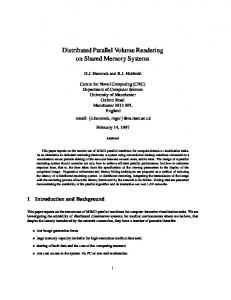
To demonstrate our time-constrained renderer, we present the results for images produced with and without time constraints all rendered at 1200 × 1200 resolution. We change the bounds for each test to give an overall sample of what can be achieved. The first scene we demonstrate is the Cornell box. We use a crex of (TTMRGD)* for the rendering. For this experiment we set the time constraints to two-thirds and one-third of the time required to fully render the crex. Figure 6 demonstrates the resultant images. The full render (left) took 150 seconds. The second image (middle) under a time constraint of two-thirds the original (100 seconds) took 63 seconds to complete, and execute the complete TTMRG portion of the crex. The final image (right) was rendered in 49 seconds. This is just a fraction under its timing bound of one-third of the original (50 seconds), with the TTM portion of the crex executed. The second scene is the view of the showcase from the library scene. For this test we pre-calculated the cost of rendering the primary rays (slightly under three minutes) and began our test rounding up by one minute for each different scene. The crex chosen for these sets of renderings was (TT[RS]G)*D. Figure 7, demonstrates the resultant images. Under a five minute time constraint (left), the result is equivalent to a crex of (TT[RS]G)* . The second image (middle) was bound by four minutes, and in this case the crex is equivalent to TT[RS]. Finally, the three minute time-constrained image (right) was rendered with a crex equivalent to TT only. The final scene helps to highlight some of the limitations of our current implementation based solely on component-based rendering. For this experiment we calculated the cost of rendering the full crex and then used time constraints of a half of the full rendering and one quarter. Figure 8 demonstrates the resulting images from this test. We use the corridor scene with a crex of TTMRSGD for the full rendering (left). The time taken was 860 seconds. Under the time constraint of a half the full rendering (430 seconds) the rendering of the TTM portion of the crex was completed in 428 seconds. However, for the time constraint of a quarter (215 seconds), only the primary rays were rendered in 372 seconds thus failing to meet the bound.
Figure 6: Cornell box: (left) no time constraints (crex is (TTMRGD)*), (middle) two-thirds time constraints of full rendering (equivalent to a crex of (TTMRG)*) and (right) one-third time constraints of full tendering (equivalent to a crex of TTM).
Figure 7: Library scene with a view of the showcase with an attempted crex of (TT[RS]G)*D: (left) five minutes time constraint (equivalent to a crex of (TT[RS]G)*), four minutes time constraint (equivalent to a crex of TT[RS]) and (right) three minute time constraint (equivalent to a crex of TT).
Figure 8: Corridor scene: (left) no time constraints (crex of TTMRSGD), (middle) time constraints of a half the full rendering (equivalent to a crex of TTM) and (right) a time constraint of a quarter of the full rendering time (primary rays traced only).
6
Conclusions and future work
We have presented a framework for time-constrained selective rendering using components. Primarily the component-based selective rendering framework directed by crex introduces a novel level of flexibility for selective and progressive rendering, and may be extended into a perceptual rendering framework [Stokes et al. 2004]. Furthermore, in our experiment, we showed that component-based rendering could also be used for rendering individual pixels driven by an importance map. In this experiment, participants were not able to distinguish between the quality of the HQ and CBQ renderings when they were performing a visual task. Finally, the crex results from Section 5, show the potential of the component-based rendering for profiling and rendering within given deadlines. We have intentionally limited ourselves to component-based selective rendering in this paper to demonstrate the merits of this approach exclusively. One of the problems exposed in Section 5.3 was the failure to meet timing bounds, due to the need to trace all primary rays. The number of primary rays is currently fixed and the implementation follows the Radiance approach too closely. Future work will implement the framework within a more complete selective rendering system [Debattista et al. 2005] in which a decision theoretic approach [Dumont et al. 2003] could be used to decide on the best course of action.
7
Acknowledgements
D EBATTISTA , K., S UNDSTEDT, V., P EREIRA , F., AND C HALMERS , A. 2005. Selective parallel rendering for highfidelity graphics. In Proceedings of Theory and Practice of Computer Graphics 2005, Eurographics Association, 59–66. D UMONT, R., P ELLACINI , F., AND F ERWERDA , J. A. 2003. Perceptually-driven decision theory for interactive realistic rendering. ACM Trans. Graph. 22, 2, 152–181. F UNKHOUSER , T. A., AND S EQUIN , C. H. 1993. Adaptive display algorithm for interactive frame rates during visualization of complex virtual environments. In SIGGRAPH ’93, ACM Press, 247–254. G OBBETTI , E., AND B OUVIER , E. 1999. Time-critical multiresolution scene rendering. In VIS ’99: Proceedings of the conference on Visualization ’99, IEEE Computer Society Press, 123– 130. H ABER , J., M YSZKOWSKI , K., YAMAUCHI , H., AND S EIDEL , H.-P. 2001. Perceptually guided corrective splatting. In Computer Graphics Forum, vol. 20, 142–152. H ECKBERT, P. S. 1990. Adaptive radiosity textures for bidirectional ray tracing. In SIGGRAPH ’90, ACM Press, 145–154. H ORVITZ , E., AND L ENGYEL , J., 1997. Perception, attention, and resources: A decision-theoretic approach to graphics rendering. I TTI , L., KOCH , C., AND N IEBUR , E. 1998. A model of SaliencyBased Visual Attention for Rapid Scene Analysis. In Pattern Analysis and Machine Intelligence, vol. 20, 1254–1259. JAMES , W. 1890. A saliency-based search mechanism for overt and covert shifts of visual attention. In Principles of Psychology.
We would like to thank Peter Apian-Bennewitz and Stefan Jankowski for the library scene. We would also like to thank Greg Ward for technical discussions. The work reported in this paper has formed part of the Rendering on Demand (RoD) project within the 3C Research programme whose funding and support is gratefully acknowledged. This work is also partially support by Portuguese FCT grant POSI/CHS/42041/2001.
K AJIYA , J. T. 1986. The rendering equation. In SIGGRAPH ’86, ACM Press, 143–150.
References
L ARSON , G. W., AND S HAKESPEARE , R. 1998. Rendering with radiance: the art and science of lighting visualization. Morgan Kaufmann Publishers Inc.
B ERGMAN , L., F UCHS , H., G RANT, E., AND S PACH , S. 1986. Image rendering by adaptive refinement. In SIGGRAPH ’86, ACM Press, 29–37.
L ONGHURST, P., D EBATTISTA , K., AND C HALMERS , A. 2005. Snapshot: A rapid technique for driving a selective global illumination renderer. In WSCG 2005 SHORT papers proceedings.
B OLIN , M. R., AND M EYER , G. W. 1998. A perceptually based adaptive sampling algorithm. In SIGGRAPH ’98, ACM Press, 299–309.
L UEBKE , D., WATSON , B., C OHEN , J. D., R EDDY, M., AND VARSHNEY, A. 2002. Level of Detail for 3D Graphics. Elsevier Science Inc.
C ATER , K., C HALMERS , A., AND WARD , G. 2003. Detail to Attention: Exploiting Visual Tasks for Selective Rendering. In Proceedings of the Eurographics Symposium on Rendering, 270– 280.
M ACIEL , P. W. C., AND S HIRLEY, P. 1995. Visual navigation of large environments using textured clusters. In SI3D ’95: Proceedings of the 1995 symposium on Interactive 3D graphics, ACM Press, 95–ff.
C HEN , S. E., RUSHMEIER , H. E., M ILLER , G., AND T URNER , D. 1991. A progressive multi-pass method for global illumination. In SIGGRAPH ’91, ACM Press, 165–174.
M ASON , A. E. W., AND B LAKE , E. H. 1997. Automatic hierarchical level of detail optimization in computer animation. Computer Graphics Forum 16, 3, C191–C199.
C LARK , J. H. 1976. Hierarchical geometric models for visible surface algorithms. Commun. ACM 19, 10, 547–554.
M ITCHELL , D. P. 1987. Generating antialiased images at low sampling densities. In SIGGRAPH ’87, ACM Press, 65–72.
C OHEN , M. F., C HEN , S. E., WALLACE , J. R., AND G REEN BERG , D. P. 1988. A progressive refinement approach to fast radiosity image generation. In SIGGRAPH ’88, ACM Press, 75– 84.
M YSZKOWSKI , K. 1998. The Visible Differences Predictor: Applications to global illumination problems. In Eurographics Workshop on Rendering, 223–236.
DALY, S. 1993. The visible differences predictor: an algorithm for the assessment of image fidelity. 179–206.
KOCH , C., AND U LLMAN , S. 1985. Shifts in selective visual attention: towards the underlying neural circuitry. In Human Neurobiology, vol. 4, 219–227.
O’S ULLIVAN , C., H OWLETT, S., M C D ONNELL , R., M ORVAN , Y., AND O’C ONOR , K. 2004. Perceptually adaptive graphics. In Eurographics State of the Art Reports.
PAINTER , J., AND S LOAN , K. 1989. Antialiased ray tracing by adaptive progressive refinement. In SIGGRAPH ’89, ACM Press, 281–288. P RIKRYL , J., AND P URGATHOFER , W. 1999. Overview of perceptually-driven radiosity methods. Tech. Rep. TR-186-299-26, Vienna, Austria. R AMASUBRAMANIAN , M., PATTANAIK , S. N., AND G REEN BERG , D. P. 1999. A perceptually based physical error metric for realistic image synthesis. In SIGGRAPH ’99, ACM Press/Addison-Wesley Publishing Co., 73–82. S HIRLEY, P. 1990. A ray tracing method for illumination calculation in diffuse-specular scenes. In Proceedings of Graphics Interface ’90, Canadian Information Processing Society, Toronto, Ontario, 205–12. S ILLION , F., AND P UECH , C. 1989. A general two-pass method integrating specular and diffuse reflection. In SIGGRAPH ’89, ACM Press, 335–344. S LUSALLEK , P., S TAMMINGER , M., H EIDRICH , W., P OPP, J.-C., AND S EIDEL , H.-P. 1998. Composite lighting simulations with lighting network. IEEE Computer Graphics and Applications 18, 2 (/), 22–31. S TOKES , W. A., F ERWERDA , J. A., WALTER , B., AND G REEN BERG , D. P. 2004. Perceptual illumination components: a new approach to efficient, high quality global illumination rendering. ACM Trans. Graph. 23, 3, 742–749. S UNDSTEDT, V., C HALMERS , A., C ATER , K., AND D EBATTISTA , K. 2004. Top-down visual attention for efficient rendering of task related scenes. In Vision, Modeling and Visualization. S UNDSTEDT, V., D EBATTISTA , K., L ONGHURST, P., C HALMERS , A., AND T ROSCIANKO , T. 2005. Visual attention for efficient high-fidelity graphics. In Spring Conference on Computer Graphics (SCCG 2005). WALD , I., P URCELL , T. J., S CHMITTLER , J., B ENTHIN , C., AND S LUSALLEK , P. 2003. Realtime Ray Tracing and its use for Interactive Global Illumination. In Eurographics State of the Art Reports. WALLACE , J. R., C OHEN , M. F., AND G REENBERG , D. P. 1987. A two-pass solution to the rendering equation: A synthesis of ray tracing and radiosity methods. In SIGGRAPH ’87, ACM Press, 311–320. WARD , G. J., RUBINSTEIN , F. M., AND C LEAR , R. D. 1988. A ray tracing solution for diffuse interreflection. In SIGGRAPH ’88, ACM Press, 85–92. YARBUS , A. 1967. Eye movements during perception of complex objects. In Eye Movements and Vision, 171–196. Y EE , H., PATTANAIK , S., AND G REENBERG , D. 2001. Spatiotemporal sensitivity and Visual Attention for efficient rendering of dynamic Environments. In ACM Transactions on Computer Graphics, vol. 20, 39–65.