Materials 2013, 6, 2892-2957; doi:10.3390/ma6072892 OPEN ACCESS
materials ISSN 1996-1944 www.mdpi.com/journal/materials Review
Self-Ordered Titanium Dioxide Nanotube Arrays: Anodic Synthesis and Their Photo/Electro-Catalytic Applications York R. Smith 1, Rupashree S. Ray 1, Krista Carlson 1, Biplab Sarma 1 and Mano Misra 1,2,* 1
2
Metallurgical Engineering Department, University of Utah, Salt Lake City, UT 84112, USA; E-Mails:
[email protected] (Y.R.S.);
[email protected] (R.S.R);
[email protected] (K.C.);
[email protected] (B.S.) Chemical Engineering Department, University of Utah, Salt Lake City, UT 84112, USA
* Author to whom correspondence should be addressed; E-Mail:
[email protected]; Tel.: +1-801-581-6386; Fax: +1-801-581-4937. Received: 1 March 2013; in revised form: 2 May 2013 / Accepted: 5 June 2013 / Published: 16 July 2013
Abstract: Metal oxide nanotubes have become a widely investigated material, more specifically, self-organized titania nanotube arrays synthesized by electrochemical anodization. As a highly investigated material with a wide gamut of applications, the majority of published literature focuses on the solar-based applications of this material. The scope of this review summarizes some of the recent advances made using metal oxide nanotube arrays formed via anodization in solar-based applications. A general methodology for theoretical modeling of titania surfaces in solar applications is also presented. Keywords: anodization; metal oxide nanotube arrays; photoelectrochemistry; photocatalysis; density functional theory
1. Introduction Research focused on the synthesis, characterization, and applications of nanomaterials has recently become a common ground between many scientist and engineers from a variety of fields. Due to the small size of these materials (×10−9), they often exhibit exciting electronic, optical, and mechanical properties due to their small geometry. The late Nobel laureate physicists, Richard P. Feynman [1], first envisioned this area of research in his talk ―There’s Plenty of Room at the Bottom‖ at the
Materials 2013, 6
2893
American Physical Society meeting at Caltech in 1959; however it was not until 1974 that this field was coined the name nano-technology by Norio Taniguchi [2]. One class of materials that has recently received considerable interest for a wide variety of catalytic applications is nanostructured transitional metal oxides: in particular, one-dimensional (1D) nanostructured metal oxides such as nanowires, nanorodes, and nanotubes. This class of materials has been widely researched due to their many applications [3]. These materials are generally synthesized using either physical (top down) or chemical (bottom up) techniques. Of the variety of synthesis methods, electrochemical synthesis methods have shown promise to synthesize a number of metal oxide nanostructures [4,5], in particular electrochemical anodization of so-called valve metals and their alloys [6,7]. Through the use of various processing techniques, a wide variety of nanostrucutres can be synthesized with high control. The synthesis of vertically orientated self-ordered metal oxide nanotube arrays on metal substrates using electrochemical anodization technique have been reviewed [6–8], as well as their application in solar energy conversion systems [9–13]. Although several highly ordered nanotubular-type oxide structures of various valve metals and their alloys have been achieved through electrochemical anodization, this review will focus on some of the more recent metal oxide nanotube architectures that have demonstrated solar-based applications, more specifically titania nanotube arrays. A basic methodology for theoretical modeling of titania surfaces for some solar-based applications is also presented. 1.1. Electrochemical Anodization Keller et al. [14] first reported the formation of porous anodic alumnia using an electrochemical anodization technique. Subsequently this synthesis method has been extended to several other valve metals and their alloys to form highly self-ordered nanostructures. Despite previous efforts, it was not until the recent works by Hebert et al. [15,16] that a quantitative relationship of oxide dissolution and nanoporous film formation on Al and Ti had been established. These works focused on aluminum (Al) and titanium (Ti) but can potentially be applied to other metals. The basis of nanoporous film formation via anodization involves a combination of ionic migration in the formed oxide and stress-driven interface diffusion of metal atoms. A differentiating feature between Al and Ti is that when Al is anodized it generally forms a porous oxide layer, whereas anodization of Ti generally forms a nanotubular oxide layer [17] where separate, individual tubes are formed. Raja et al. [18] suggested that faster generation of cation vacancies by accelerated dissolution and radial transport of vacancies across the pore walls could be the cause of tubular formation when anodizing Ti in fluoride containing electrolytes. Valota et al. [19] attributes the separation of nanotubes formed on titania as a result of dissolution of a fluoride rich layer formed at the cell boundaries of the nanotubes; however, this does not explain the separation of nanotubes in fluoride free electrolytes [20,21]. More recently, Su et al. [17] proposed a new model based on localized dielectric breakdown during the anodization process. This said mechanism suggests that oxygen filled voids can be generated at the barrier oxide layer of anodic oxides due to localized dielectric breakdown of the oxide. The number and size of such voids increase with the degree of localized dielectric breakdown and the accumulation of these voids at the cell boundary areas causes the separation of
Materials 2013, 6
2894
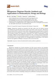
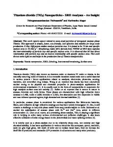
neighboring pores [17]. Nevertheless, there is still no generally accepted explanation for metal oxide nanotubular formation via electrochemical anodization process. Zwilling and co-workers reported the anodization of titanium using fluoride-containing electrolytes in 1999 [22,23]. Nanoporous oxide layers were observed in their studies. Gong et al. [24] demonstrated experimental conditions to obtain high-quality and well-ordered T-NTA in acidic fluoride electrolytes. Subsequently, the work of Macak et al. [25,26] developed critical parameters required to synthesize well-ordered titania nanotubular arrays (T-NTA) as well as the work of Raja et al. [18,27] for various electrolytes. In these methods, a Ti substrate typically in the form of a metal foil (~0.2 mm) is used as an anode during the anodization process. Thin films of Ti (350–1000 nm) have also been successfully used to grow T-NTA. Deposition of Ti on conducting substrates, such as conductive glass (indium tin oxide, ITO) has been carried out using radio frequency sputtering [28]. Anodization of Ti films deposited on Si substrates via DC sputtering [29–31], as well as e-beam deposited films [32] have also been reported. T-NTA have also been synthesized using other Ti substrate geometries such as thin wires [33–35] and meshes [36–38] and curved surfaces [39]. These studies demonstrate the versatility of electrochemical synthesis methods on any substrate geometry. Formation of other metal oxide nanotube arrays that have demonstrated photoelectrochemical applications include hematite nanotubes using iron foil [40,41] and low carbon steel [42], TaON nanotubes from Ta2O5 nanotubes [43], as well as other Ti-based alloys such as TiN [44], TiPd [45], TiW [46], TiRu [47], TiNbZr [48], among others. Images of various nanotubes are shown in Figure 1. Figure 1. (a) Top view SEM micrograph of titania nanotube arrays fromed by electrochemical anodization, with the inset showing the base of the nanotube arrays; (b) side vide of the titania nanotube arrays; (c) TaON nanotubes formed by nitridization of Ta2O5 nanotubes (Reprinted with permission from [42], Copyright by The Royal Society of Chemistry); (d–e) Fe2O3 nanotubes formed by (Reprinted with permission from [40], Copyright by the IOP Publishing).
Materials 2013, 6
2895
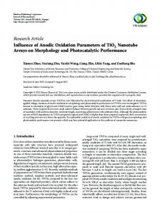
The electrochemical baths typically used in the anodic formation of metal oxide nanotubes consist of a fluorinated inorganic (e.g., 0.5 M H3PO4 + 0.14 M NaF) or organic (e.g., 0.2–0.5 wt % NH4F + 0.2–10 wt % H2O in ethylene glycol/glycerol) based electrolyte. Important parameters in determining the dimensions of the T-NTA include anodization potential (1–150 V, D.C.), anodization time (15 min. to several hours), pH, temperature, and fluoride content. The diameter of the nanotubes is essentially determined by the anodization potential and is linear relationship where an increase in potential results in an increase in diameter. Fluoride content and bath temperature are controlling variables in the wall thickness of the nanotubes. Lower temperatures typically yield thicker nanotubes while higher fluoride content gives thinner nanotube walls. The length of the nanotubes is a strong function of electrolyte pH. Low pH electrolytes results in shorter nanotube lengths regardless of anodization time as a result of self-etching (vide infra). Electrolytes with pH~6, such as organic-based electrolytes, can be anodized for longer times and yield much longer nanotubes (up to several microns). A schematic of a typical anodization setup is shown in Figure 2. The experimental setup consists of a two-electrode configuration. The metal to be anodized serves as the anode while a Pt flag of larger area than the anode material serves as the cathode. Potentiostatic anodization is commonly used where the potential is ramped from free corrosion potential to the pre-determined anodization potential. One study [49] examined the galvanostatic anodization on the formation of T-NTA. In this study the authors observed oscillation in the voltage with time, which eventually resulted in unstable oxide films. Other techniques such as pulse voltage anodization [50] have also been applied as well, although similar nanotube morphology is obtained compared to potentiostatic anodization methods. Figure 2. Typical electrochemical anodization setup for the synthesis of metal oxide nanotube arrays utilizing (a) magnetic stirring and (b) ultrasonication agitation methods. During ultrasonication, to prevent electrolyte heating for prolong synthesis time, the sonication bath temperature is controlled.
During the anodization process, the electrolyte bath is commonly mechanically stirred. It was not until the recent works by Sánchez-Tovar et al. [51,52] that a detailed study on the effects of hydrodynamic
Materials 2013, 6
2896
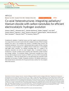
conditions on T-NTA formation was presented. In these studies a rotating disc electrode was used and the effects of flouride concentration (diffusion limited conditions) and Reynolds number on T-NTA were examined. These studies concluded that highly defined nanotubes can be synthesized using defined flow conditions, in particular the nanotube top morphology, which plays a cruial role in photoelectrochemical applications [52]. Other methods of bath agitation such as ultrasonication have also been studied [53]. The use of ultrasonication during anodization, or sonoelectrochemical anodization, results in a more ordered T-NTA morphology. The kinetics of nanotube formation was increased as evident by monitoring the anodic current during anodization. Sonoelectrochemical anodization has also demonstrated enhanced photoelectrochemical performance over photoanodes prepared using magnetically stirred anodization baths [53–55]. Recently, we examined the effect of irradiation during anodization of Ti [56]. In this investigation, we found that the nanotube morphology, i.e., wall thickness, tube diameter, and sidewall homogeneity, is greatly influenced by irradiation during anodization as well as the electronic properties. It is believed that the photoinduced holes increase the Ti4+ cation migration to the surface via Coulombic repulsive forces, which results in greater wall thickness and pore diameter. 1.1.1. Nanotube Formation Stages during Anodization Metal oxide nanotube formation in the presence of fluoride ions typically occurs in three stages as outlined by the shape of the anodization current density-time plot as shown in Figure 3: (i) initial oxide barrier layer formation; (ii) pitting/nanopore formation; and (iii) steady-state nanotube growth stage. Figure 3. A typical current density vs. time plot produced during the anodization process.
In stage (i) a large current density is initially measured at the instant of an applied anodic potential indicating the oxidation of Ti to Ti4+. A rapid decrease in current density is observed which is attributed to the formation of oxide layer via hydrolysis reaction Ti4+ + 2H2O → TiO2 + 4H+
(1)
During the hydrolysis reaction, H+ ions accumulate and to maintain electroneutrality, F− ions migrate to the H+ sites. When a critical concentration is reached at local regions, dissolution of TiO2 occurs by the formation of aqueous hexafluorotitanate Ti4+ + 2H+ + 6F− → H2TiF6
(2)
Materials 2013, 6
2897
The dissolution reaction of Ti cations creates negatively charged cation vacancies in the oxide which migrate to the metal/oxide interface as a result of the potential gradient across the oxide [57]. The presence of metal-cation vacancies near the metal/oxide interface facilitate the Ti → Ti4+ + 4e− reaction as the cations can easily hop to the available vacancy. This event is marked by an increase in current density (stage ii). During this stage, nucleation of nanopores occurs at the oxide surface. Subsequently, steady-state growth of the nanotubular oxide layer is observed when the current density achieves a constant value over time (region iii). It should be noted that the anodic current density during anodization is comprised of two components: the first is current due to the dissolution process at the oxide/electrolyte interface, and the second is current due to the oxidation of titanium at the metal/oxide interface [9]. Moreover, pH of the electrolyte plays a large role in the pore nucleation and growth of the nanotubes as the dissolution rate of the oxide increases with a decrease in pH [58]. Anodization of other metals in a fluorinated electrolyte follows a similar mechanism, for example anodization of Fe to form Fe2O3 nanotube arrays [40–42]. 1.1.2. Formation of Complex Nanotube Geometries Electrochemical anodization allows for growing a variety of tubular- and hierarchical-type nanostructures by changing a few synthesis variables. For example, formation of branching T-NTA is a result from step changes in the voltage during anodization [59–61]. However, to form branching tubes, the voltage is not alternated but maintained at the new voltage until chemical and field-assisted reactions (i.e., oxidation, ion migration and dissolution) have equilibrated and the branched tube has reached the desired length. Chen et al. reported that the number of tube branches could be controlled by reducing the applied voltage by a factor of 1 n , where n determined the number of branches [60]. Complex multilayer structures were fabricated as adjustments in voltage caused either an increase or decrease in branching. Mohammadpour et al. observed the formation of large diameter tubes from the combination of smaller diameter tubes during anodization in low fluorine, viscous electrolytes at high potentials [59]. It was suggested that this structure was the result of the combination of strong capillary forces banding the tubes together and the inhibition of electrolyte between the spaces of adjacent nanotubes. Proposed applications for this hierarchical structure included molecular separation in microfludic techniques and photovoltaics owing to the higher surface area and better charge separation at the ―core-leg‖ interfaces [59]. Bamboo T-NTA structures can be formed through electrolyte chemistry modifications as well as alternating applied bias. The banded, bamboo-like structure can occur in aqueous or high water content glycerol electrolyte solutions [62,63]. However, glycerol solutions containing glycerol/H2O ratios higher than 9:1 do not exhibit nodes due to the lack of periodical current fluctuations at the T-NTA surface. No nodes are observed when ethylene glycol replaces glycerol at similar ratios. This observation was attributed to the higher diffusion constant of the EG, which reduced the fluctuations in current density during tube formation. More control over the node thickness and frequency is provided by the application of an alternating bias in an ethylene glycol based solution [64]. Bamboo structures are often used in applications such as DSSC where maximized dye loading is necessary. Although the stratification between the nanotubes causes a longer random path for photogenerated charges, improvements in incident photon to current efficiency (IPCE) are still observed due to the additional
Materials 2013, 6
2898
surface area provided by the nodes. The bamboo rings allow for a higher rate of dye loading due to extra surface area. The extra space introduced between the tubes due to the rings also allow dye molecules to cover the exterior of the NT walls [64]. Kim et al. reported that bamboo structures with 70 nm spacing between the compact nodes provided the largest increase in photoactivity [64]. Hierarchical structures of T-NTA such as nanolace-type structures atop the nanotube arrays can be achieved by alternating voltage technique [65] or through surface treatments [66–68]. Double walled T-NT have also been synthesized using an ionic liquid fluoride solution in ethylene glycol [69]. The common synthesis technique adopted for growing hierarchical-type T-NTA involves a two-step anodization process. First, T-NTA are grown on a Ti substrate and subsequently removed via ultrasonication for a long duration, leaving a patterned Ti substrate. The as-formed substrate is then subject to a second anodization, resulting in smooth nanotubes with a nanoporous/nanolace top layer. Recently we have demonstrated a simple surface etching treatment such that T-NTA can be synthesized by a single anodization process at constant voltage [68]. 1.1.3. Crystallization of Nanotubes The as-anodized oxide layer formed is amorphous in nature. For many applications, the amorphous crystal structure is too disordered and does not have desirable electronic properties. Generally, crystallization is achieved through thermal treatment at 350–500 °C in a variety of atmospheres. In the case of T-NTA, of the three crystal structures of titania (rutile, anatase, and brookite) a mixture of anatase and rutile are the primary crystal structures obtained after thermal annealing in either air or oxygen whereas annealing in inert (N2) or a reducing atmosphere (H2/N2) result in primarily anatase phase titania [70]. For solar-based applications, predominantly anatase phase titania is most desirable [71]. Although anatase and rutile are the primary crystal structures obtained through thermal treatments, a recent study has demonstrated the formation of brookite T-NTA between 470 and 500 °C in air [72]. Other methods examined to form crystalline T-NTA via non-thermal routes are by hydrothermally treatments [66] or by soaking them water at room temperature for an extended period of time (days) [73]. Despite the perceived benefits of such methods to obtain crystalline T-NTA, for solar-based applications, thermal treatment results in the most photoactive oxide layer for T-NTA [74]. 1.2. Surface & Bulk Properties of TiO2 Although TiO2 naturally occurs in several different polymorphic forms, anatase and rutile are the most commonly studied phases for nanomaterials used in photocatalyic applications [75]. The basic structure of both anatase and rutile contains titanium in six-fold coordination with oxygen [75,76]. Differences between the two phases arise from the connection of the octahedrally coordinated Ti cations; anatase octahedra share four edges and are connected in staggered chains parallel to the [221] direction, while the octahedra in rutile form chains along [001] direction with only two shared edges [76]. Polymorph stability is dependent upon synthesis method and crystallite size [75–78]. At macroscope levels, rutile is the most thermodynamically stable phase under ambient conditions. However, as crystallite size drops below 13 nm, anatase becomes the stable phase [76,79]. This phase change suggests that many of the ordinary physics and chemistry rules of bulk materials no longer apply at the nanolevel, allowing their properties to differ substantially [78].
Materials 2013, 6
2899
The relationship between the bulk and surface chemistry of a material becomes apparent when examining the surface charge that develops when it is placed in an aqueous solution. When immersed in an aqueous solution, the charge that develops on an oxide surface is mainly dependent upon the electronegativity of the cations in the material and the solution pH [80]. However, these values have been found to vary depending on polymorph, different crystallographic planes, crystallite size, as well as synthesis and measurement methods. For example, Mandzy et al. [81] reported the isoelectric point (IEP) of different sized nanoparticles of antase and rutile: 5 nm anatase–pH 4, 25 nm anatase–pH 5.5 and 10 nm rutile–pH 3.2. As commercially available materials, the synthesis method was not listed; however, the 5 nm anatase value differed from the pH~5.5 reported by Penn et al. [76] where 5 nm particles were created via a sol gel method. This discrepancy is most likely the result of the technique used to obtain the IEP value. In Mandzy’s study, the IEP was measured using a zetameter, while Penn relied on the gelling of suspensions. Difference in crystallite size could account for the discrepancy between Mandzy’s 10 nm rutile particles exhibiting an IEP of pH 3.2 and 2 mm diameter particles formed by Bullard et al. [82] which had an IEP of pH 5.2. Bullard also demonstrated the variation between crystallographic planes with IEP ranges for the (100), (110) and (001) surfaces of rutile as 3.2–3.7, 4.8–5.5, and 5.5–5.8, respectively. Differences between polymorphs and crystal surfaces can be explained through surface chemistry. Bullard theorized that differences between Ti and O coordination caused the variation in IEP. It was suggested that higher IEP values for the (001) surface were due to stronger and more numerous Lewis base sites. The increased quantity and strength of these electron-donating oxygen positions facilitated more adsorption of solvated hydrogen ions. The (001) surface is also more open than the (100) and (110) plane, promoting high charge mobility, and hence would be the preferred orientation in electrochemical experimentation. The relationship between surface acidity and nanotube structure was examined extensively by Kitano et al. [83]. In this study, Fourier transform infrared (FT-IR) spectroscopy was used to examine TiO2 nanosheets and nanotubes with similar crystal structures. Nanotubes and nanosheets were found to possess both Bronsted and Lewis acid sites; however, nanotubes were found to exhibit higher Bronsted acidity than the nanosheets. It was suggested that the higher concentration of bridging OH vs. terminal OH groups found on nanosheets, and the distortion of the Ti octahedra, allowed for nanotubes to have higher catalytic activity than the nanotsheets. Still, few surface aciditiy studies have been performed on titania nanotubes formed via anodization, leaving this area in need of further investigation. However, many common surface modifications, along with their effect on photocatalytic reactions, are discussed in the following sections. 1.3. Photocatalysis and Photoelectrochemistry The photovoltaic effect is a phenomena in which a voltage or electrical current is created in a material by being exposed to electromagnetic radiation, light energy more specifically, and is the basis of semiconductor photocatalysis and photoelectrochemistry. The French scientist Alexandre-Edmond Becquerel first reported witnessing this effect in 1839 [84]. Several advances between the 1950’s and 1970’s improved the understanding of electrochemical interactions between semiconductor-liquid interfaces, namely by Gerischer, Memming, and Williams, among others [85–87]. These studies
Materials 2013, 6
2900
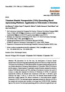
resulted in establishing a fundamental understanding of the semiconductor-electrolyte interface including kinetics and energetics of charge transfer across the semiconductor-electrolyte junction. Despite these early fundamental studies, it wasn’t until the 1970’s works’ by Fujishima and Honda that first demonstrated the potential application of photoelectrochemical systems for energy conversion and storage [88,89]. Their initial studies demonstrated that the oxidation of water could be carried out at a less negative potential compared to the standard redox potential when a titania surface is irradiated with light energy greater than the material’s band gap. These results initiated the realization that sunlight could be used to split water into hydrogen and oxygen, a process commonly referred to as photoelectrolysis [90]. Solar energy is an attractive energy source for energy conversion and storage as nearly enough solar energy strikes the earth in one hour to meet nearly all our global energy demands for an entire year [91]. Over the years there have been numerous studies on semiconductor photocatalytic and photoelectrochemical systems for hydrogen generation (water splitting reaction) of which have also been extend to many other areas such as electrochemical photovoltaics [92–94], wastewater remediation [95,96], antibacterial/self-cleaning surfaces [97,98], and fuel synthesis [99], among others. Figure 4 shows a schematic of a liquid-junction photoelectrochemical cell. It consists of a photoanode, a counter electrode cathode, and a reference electrode. In a typical PEC setup, semiconductors utilize light irradiation to promote reactions on the surface of the electrodes within the system. This example considers n-type semiconductors, as they have generally shown better stability. The principles and applications of p-type materials are generally similar to n-type materials. Oxidation of the electrolyte (e.g., H2O) occurs at the anode and reduction occurs at the cathode. Figure 4. Schematic of a liquid junction photo-electrochemical cell for a p-type semiconductor for the reduction of carbon dioxide to various products. A similar setup is used for n-type cells as well. The anode (1) is the photoactive material; (2) is the cathode; (3) a conducting electrolyte; (4) reference electrode; (5) potentiostat. The Fermi level of the semiconductor is denoted by Ef. Figure adapted from Reference [100].
Materials 2013, 6
2901
An innate property that makes semiconductors useful for PEC is their discrete quantum states of electrons. Unlike metals that have a continuum of electron states (bands), semiconductors exhibit an electrical resistivity, or rather an energy band gap (Eg) that extends from the top of the filled valance energy band (VB) to the bottom of the vacant conduction energy band (CB). In general, when a semiconductor surface is exposed to light radiation (hν ≥ Eg) electron hole pairs (e˗CB + h+VB) are generated, represented by Equation 1 with heat generation for the reverse reaction. Photocatalyst → (e˗CB + h+VB)
(3)
photocatalyst + (e˗CB + h+VB) → Δ(heat)
(4)
Upon photo-excitation of an electron from the VB to the CB, the e˗CB and h+VB pairs can follow several pathways (Figure 5A). Ideally, in a PEC cell the photo-generated e˗CB’s are driven to the external circuit and subsequently to the cathode with a small bias potential. The h+VB’s can then migrate to the surface of the semiconductor to oxidize any absorbed molecules or solvent on the surface. The ability for a photocatalyst to carry out redox reactions and facilitate effective and efficient charge transfer is predisposed to two criteria are often required: (i) effective charge separation; and (ii) the catalysts’ ability to absorb reacting species on its surface. At the surface of the semiconductor, electrons can also be donated to an acceptor species and likewise the holes can migrate to the surface to combine with electrons from a donor species as well (Figure 5, path a and b). However, the recombination of electrons and holes prevents them from transferring to the surface to react with absorbed species. Recombination can occur within the volume of the semiconductor or on the surface of the semiconductor (Figure 5, path c and d). The rate at which charge transfer occurs depends up the position of the bands and the redox potential of the absorbed species of interest. Figure 5. (A) Schematic of photoexcitation in a solid volume followed by recombination events. Paths a and b represent surface scavenging events while paths c and d respresent inner volume and surface recombination events. Figure adapted from Reference [100]; (B) A photocatalytic system where the energy bands (VB and CB) act as the anode and cathod in a PEC system. Figure adapted from Reference [100].
(A)
(B)
For photocatalytic systems, Bard’s concept [101] can be applied. This concept suggests that semiconductor particles can act as a short-circuited PEC cell by providing both oxidizing and reducing
Materials 2013, 6
2902
sites for the reaction (Figure 5B). When comparing the two systems, the photocatalytic system is simpler and easy to construct. Some important factors that should be met for optimal performance of a photocatalytic include:
The redox potential of the photogenerated VB hole should be sufficiently positive for the hole to act as an acceptor; The redox potential of the photogenerated CB electron should be sufficiently negative for the electron to act as a donor; Photocatayst should be economically available and be environmentally inert; Photocatalyst should be stable in a wide pH range and in a variety of electrolytes.
2. Aqueous Photocatalytic Mineralization The ability to efficiently and inexpensively degrade organic pollutants and inactivate bacteria is important as industrial, agricultural and residential waste streams continue to increase with the growing world population. Titania substrates have been studied extensively as catalysts in photo-reactive oxidation reactions for the decontamination of groundwater and wastewater streams. Of the metal oxide nanotube arrays formed by electrochemical anodization, T-NTA is the most studied material. In comparison to titania nanoparticle systems, T-TNA provide a number of benefits. For example, post-treatment recovery of titania nanoparticles from slurry reactors is inefficient and expensive [102]. Immobilizing titania nanoparticles has been carried out on conducting substrates to counter this problem [103–106]. However, when the titania is cast as films a significant reduction in surface area occurs causing degradation times to be prolonged [107,108]. More efficient pollutant degradation using T-NTA over compact titania surfaces can be attributed to fewer interfacial grain boundaries which promotes better charge separation and improved redox activity [109]. The following section will address the photooxidative mineralization of organics, the inactivation of microorganisms, as well as carbon dioxide reduction to fuels. 2.1. Organic Pollutants Titania photooxidation of organic pollutants can occur via interactions with oxidizing radicals and/or photogenerated holes [110,111]. The position of the TiO2 band edges, as well as the redox potentials of the pollutant are crucial in determining what type of PC reactions will take place. Degradation in aqueous solutions is typically the result of interactions with reactive radical ions. Under irradiation (hν > Eg), photogenerated charges react with H2O to form superperoxo (O2•−) and hydroxyl radicals (OH•). Interaction of the organic (e.g., dye molecule) with free or surface bound radicals causes mineralization as illustrated in Figure 6. Complete destruction of the organic results in CO2 and mineral acids and can be expressed as follows [111–113]: TiO2 + hν → TiO2 (eCB− + hVB+)
(5)
TiO2 (eCB− + hVB+) →TiO2 + heat
(6)
TiO2 (hVB+) + H2O →TiO2 + H+ + OH•
(7)
TiO2 (hVB+) + OH• →TiO2 + OH•
(8)
Materials 2013, 6
2903 TiO2 (eCB−) + O2 →TiO2 + O2•−
(9)
O2•− + H+ → HO2•
(10)
Dye + OH• → degradation products
(11)
Dye + hVB+ → oxidation products
(12)
Dye + eCB− → reduction products
(13)
Figure 6. Photooxidative degradation of organic pollutants through interaction with surface bound hydroxyl radicals.
Photooxidation can also occur through direct charge transfer between TiO2 and the organic pollutant. The effectiveness of TiO2 to act as a photocatalyst in these degradation reactions is due to the position of the energy band on the electrochemical potential scale [110,111,114,115]. The position of the conduction and valence band edges becomes even more important in situations where it is thermodynamically favorable for the photogenerated charges to be directly scavenged by the pollutant [114–117]. An example of this process is the oxidation of methanol where charges are directly transferred from the TiO2 surface to methanol and its degradation products [114]. The primary oxidation product of methanol, the methoxy radical, is a strong reducing agent in this situation in that it is able to transfer another electron to the conduction band (CB) of TiO2. This process, illustrated in Figure 7 (reaction a), is an example of the photocurrent-doubling effect [114], as two electrons in the CB have been generated upon the absorption of one photon. The band-edge position of TiO2 is suitable for many PC activities; however, it is often desirable to reduce the magnitude of the band gap to make visible light-induced reactions thermodynamically favorable. The degradation reaction pathways described above are different for photosensitized oxidation reactions, where the photo-process is initiated through visible light absorption of a sensitizer [112,114]. This process, shown in Figure 7 (reaction b) with a typical dye sensitizer, can be considered indirect photocatalysis, as visible light excitation of the sensitizer leads to electron injection from the excited molecule into the conduction band of the TiO2. The cationic dye radicals generated from reaction are as follows:
Materials 2013, 6
2904 Dye + hν → Dye*
(14)
Dye* + TiO2 → Dye•+ + TiO2 (eCB−)
(15)
TiO2 (eCB−) + O2 → O•− + TiO2
(16)
Dye•+ → degradation products
(17)
Dye radicals can be completely mineralized through reactions with hydroxyl radicals (Equations 14 and 15) or interact with peroxo compounds (O2•−; HO2• or HO•−) to form intermediates that eventually decompose to CO2 and H2O (Equations 20–24): Dye•+ + OH− → Dye + HO•
(18)
Dye + 2HO• → H2O + oxidation products
(19)
O2•− + H+ → HO2•
(20)
HO2• + H+ + TiO2 (eCB−) → H2O2 + TiO2
(21)
H2O2 + TiO2 (eCB−) → HO• + HO− + TiO2
(22)
Dye•+ + O•− → DO2 → degradation products
(23)
Dye•+ + HO2• (or HO•) → degradation products
(24)
Figure 7. Schematic of the (a) photocurrent-doubling effect where the absorption of one photon by methanol can lead to the generation of two electrons in the TiO2 CB; and (b) dye sensitization of TiO2 leading to an injection of an electron into the conduction band.
2.2. Surface Charge The rate of photomineralization is highly influenced by solution pH, as it alters the surface charge of TiO2 and the ability of oppositely charged species to adsorb to its surface [114,116,118–120]. The effect of this parameter is dependent upon the ions present in solution. In acid or basic conditions, the
Materials 2013, 6
2905
surface of titania can become positively or negatively charged, respectively. The zero-point charge pH (pHZPC) of titania depends on the synthesis method, but has been reported between 6 and 7 for titania nanotubes [119,121]. Thus, for pH values less then pHZPC the surface is positively charged due to H+ ions and for pH values greater than pHZPC, the titania surface becomes negatively charged due to OH−. In the case of chlorophenols, which have a negative charge at low pH, Ku et al. [118] reported that low pH solutions encourage PC degradation because TiO2 carries a net positive surface charge. However, reports of higher decomposition rates with high pH values is also reported [119]. Increased photooxidation rates in increasingly more basic medium can be attributed to an increase in hydroxyl radical formation as the hydroxide ions scavenge the holes to form hydroxyl radicals (OH− + h+→ OH•). The presence of interfering adsorbing species, such as inorganic anions (i.e., chloride, sulfate, nitrate), can diminish photo-induced organic mineralization [116,119]. The inhibitive effect is due to the occurrence of competitive adsorption onto the TiO2 surface. Chlorine ions are strong retarders of photooxidation as it not only readily adsorbs to TiO2, but can also scavenge holes and hydroxyl radicals. Inorganic anions are charged species, and as such, the extent of interference is dependent on solution pH. Liang et al. reported on both the effect of Cl− ions on 2,3-dichlorophenol (2,3, DCP) decomposition rate, as well as the effects of NO3−, H2PO4− and SO42− [119], in solutions of pH 5.3. As the Cl− ion concentration increased from 0 to 0.1 M, the decomposition of 2,3-DCP after 300 min decreased from 93% to 64%, respectively. Photo-decomposition rates using 0.05 M anion concentrations of Cl−, NO3−, H2PO4− and SO42− also exhibited lower photo-decomposition rates. As the surface charge of TiO2 is positive at a pH of 5.3, the divalent SO42− ion has the highest inhibitory effect on decomposition due to its stronger competitive adsorption. Similar to Cl−, SO42− can also inhibit photodegradation through the entrapment of positive holes and/or hydroxyl radicals. This observation changes, however, as the pH is increased to 6. Brugnera et al. reported that as the surface charge of the TiO2 became more neutral, SO42− ions had little effect on the degradation of Bisphenol A [116]. However, the presence of NO3− cut the decomposition performance nearly in half. It was suggested that this inhibitory effect occurred due to nitrate absorption of UV light, causing the transformation from nitrate to nitrite, and subsequently blocking irradiation from the TiO2 surface. The reduction of molecular oxygen at the surface of TiO2 can act as a rate-limiting step in the photocatalytic degradation of organic pollutants [111,119]. When molecular oxygen is present at the surface of TiO2, it can act as an electron acceptor and remove photogenerated electrons. As this transfer process is slow, adsorbed oxygen should be excess of the electrons to maximize this transfer rate. While levels below ~8 mg/L of dissolved oxygen show lower degradation rates, concentrations above this level do not increase it significantly [119]. Dissolved oxygen levels are also affected by temperature, tending to decrease with increasing temperature. Although an increase in solution temperature leads to an increase in species oxidation rate, overall decomposition will be counteracted by the lower oxygen levels and adsorption isotherms [111]. 2.3. Nanotube Geometry Dimensional factors of the nanotubes, such as pore diameter, tube length and wall thickness, have also been reported to play a role in organic photodegradation [122–124], although varying results are found in the literature. Longer nanotubes can absorb more light; however, the depth of incident photon
Materials 2013, 6
2906
penetration is limited. Therefore, once a certain length range has been exceeded, further improvement in photocatalytic activity will no longer be observed. Another disadvantage is the limitation of organic diffusion inside of the nanotubes, which is not significantly affected by stirring [122]. Larger nanotube diameters were also found to exhibit better photodegradation, as wider pores provided improved accessibility to the organics and a lower probability of electron-hole recombination [124]. There was an observed upper limit on this increased photoactivity, with pores greater than 75 nm showing little improvement in organic decomposition. Wall thickness was reported to be the most significant parameter, as thinner walls are more efficient at channeling photogenerated charges to the T-NTA surface in PC reactions [122]. This finding is supported by the superior photodegradation capabilities of nanowires (or nano-grass) over nanotubes due to an increase in the charge transport along the narrow tube walls [125]. Photocatalytic degradation is also sensitive to titanium substrate geometry. Titania nanotubes formed on wires or mesh provide a 3D structure where improved photodecomposition occurs due to the tubes capacity to not only absorb incident light, but reflected and refracted light as well [33,126]. Nanotube coated wires also showed superior degradation capabilities over Pt loaded T-NTA coated foil [33]. 2.4. Photocataytic Inactivation of Microorganisms Conventional water disinfection methods can often lead to the formation of harmful by-products [127,128]. Disinfection using TiO2 as a photocatalyst has the power to inactivate microorganisms, as well as endotoxins released upon cell death [129]. Bacterial inactivation, using Pt/TiO2 as a photocatalyst, was initially reported by Matsunaga et al. in 1985 [130]. Since this discovery, a large body of research has been produced in an attempt to clarify the TiO2 photo-induced killing mechanisms. However, this research has centered on the use of TiO2 films and NP powders. While NPs provided more surface area for bacterial interaction, limitations in their use arose due to environmental issues from difficulties in filtration from solution and their inability to be effectively regenerated and reused. The use of anodized T-NTA eliminates these issues, as an array can easily be removed from a solution and regenerated without losing any structural or photocatalytic integrity. Only recently has the inactivation of microorganisms using TiO2 nanotubes been reported [121,128,131]. Baram et al. reported on the inactivation of Escherichia coli (E. coli), examining many of the same parameters that affected organic mineralization [121]. Similar to organic decomposition, the application of an applied bias, formation of hydroxyl radicals, solution pH and the presence of inorganic ions, all affect the inactivation efficiency. Under UV irradiation (λ = 360 nm) and an applied bias of 1.5 VSCE, complete bacterial inactivation was achieved in 15 min (starting concentration of 106–107 cells/mL), whereas bacteria exposed only to UV irradiation, showed no decrease in concentration [121]. Acidic solutions (pH = 5) also showed an increase in inactivation as the negatively charge bacteria are attracted to the positively charged TiO2, increasing adsorption and cell death. Contrary to prior reports on TiO2 films and nanoparticles, TOC levels remained constant throughout the experiment; indicating that inactivated bacteria did not totally decompose into their final products (i.e., CO2).
Materials 2013, 6
2907
Similar to organic degradation, coupling of T-TNAs with narrow bandgap semiconductor and metal composite NPs simultaneously enhanced the visible light activity and charge separation efficiency, increasing the bacterial inactivation efficiency. Inactivation of E. coli under visible light irradiation was achieved by Hou et al. through the use of Ag/AgBr/T-NTA [128]. This hybrid proved not only more effective than a Pt/CdS/T-NTA hybrid, but is also more cost effective and does not experience photocorrosion [131]. 2.5. Carbon Dioxide Reduction Increasing anthropogenic carbon dioxide emissions from mobile and stationary energy systems, as well as from various industrial processes have been speculated to play a role in global climate change [132–135] and have sparked multiple initiatives to reduce CO2 emissions. One method of CO2 mitigation is through post-treatment capture and utilization (recycle). Although a relatively inert molecule, there are numerous catalytic routes for converting CO2 to value-added chemical as outlined by Xiaoding and Moulijn [136]. Due to stability of the CO2 molecule, many of the catalytic conversion methods require substantial energy input, of which should be derived from a source(s) that do not contribute to further CO2 emissions. As a result, PEC and PC reduction process for the conversion CO2 on semiconductor electrodes has gained much attention in recent years. Studies have been extended to a variety of different avenues such as analysis of various semiconductor photocatalysts [137–140], modification of photocatalyst by depositing small amounts of metal [141–143] and metal complexes [144,145], and the effects of operating conditions [146–148]. In general, the PEC and PC reduction of CO2 to low-chain hydrocarbons and simple alcohols has not been examined extensively. Halmann showed the first report of the photoelectrochemical reduction of CO2 in 1978 [137]. The photoreduction was carried out using p-type gallium phosphate (p-GaP) as the photocathode with part or all of the energy supplied by light. The products were found to be formaldehyde (HCHO), formic acid (HCOOH), and methanol (CH3OH). The majority of the studies on the PC reduction of CO2 have mainly focused around the use of nanoparticulate systems as reducing the particle size results in more active sites as well as simplified experimental setups. There are only a few reports on the PC reduction of CO2 using T-NTA in either gas or solution phase [143,149,150], which demonstrate μmol gram-catalyst−1 h−1 conversion rates. Products obtained from these studies consist predominantly of C1–C2 alcohols as well as C1–C3 hydrocarbons. Although the conversion rates are low, thermodynamic arguments are not sufficient to explain the limited conversion of CO2 to value added chemicals via a technical process. Reasons for such low conversions to value added chemicals are believed to be kinetic in origin. Since the σ-bonding orbitals of CO2 are deep down, it is deduced that only the π-orbitals of CO2 alone may be perturbed and an attack on the oxygen centers alone may be possible to activate CO2 [151]. As a result, a fundamental understanding of excited catalyst surface sites and surface states is necessary to engineer photocatalysts capable of effectively activating CO2 molecules [99,151,152] if a technical processes is to ever be developed.
Materials 2013, 6
2908
3. Photoelectro-Catalystic Pollutant Degradation The application of a low anodic bias, typically