Abstract. Complex systems have many heterogeneous aspects, which can be specified comprehensibly and adequately by viewpoint specifica- tion techniques ...
Semantical Integration of Object-Oriented Viewpoint Specification Techniques Benjamin Braatz, Markus Klein, and Gunnar Schr¨ oter Technische Universit¨ at Berlin, Germany [bbraatz,klein,schroetg]@cs.tu-berlin.de
Abstract. Complex systems have many heterogeneous aspects, which can be specified comprehensibly and adequately by viewpoint specification techniques dealing only with a suitable subset of these aspects. A methodology for the formal integration of collections of such viewpoint specification techniques is introduced and applied to object-oriented systems. As a main result, it is shown, how the semantical consistency of viewpoint specification techniques can be checked in this framework.
1
Introduction
Viewpoints as in [1] and [2] were introduced with the aim to ease the specification of complex systems. The main idea of these approaches is reduce the accessible aspects of the specification such that the developers only have to deal with those aspects of the system, that are important for the current task. The rest of the system is hidden and not considered in the viewpoint. This allows to keep the viewpoint specifications small and comprehensible. Since the single viewpoints are not assumed to be disjoint in these approaches, it is possible to specify the same aspect of a system in different viewpoints. Thus, the developers are enabled to create redundant specifications in the overlapping parts of the viewpoints, which is a means to ensure that two viewpoints have been specified with a common interpretation of the overlapping properties. But at the same time, the viewpoint based approaches allow the specification of inconsistent systems, this means to use a contradictory specification of the same property in different viewpoints. Thus, the application of a viewpoint guided software engineering process should contain a check of consistency. This work, as part of the national priority program on “Integration of Software Specifications for Applications in Engineering” (see [3]), is concerned with such consistency checks. In [4] a first idea of a consistency check by the construction of a selected semantic model was presented by an example. This paper is meant to give a formal and more detailed explaination of the constructions needed for the intended semantic integration. Semantic integration in this sense needs a common semantic domain for the used specification techniques. We decided to use an object-oriented instantiation of the transformation systems of Große-Rhode (see [5]) for this purpose. It has been shown in a number of small case studies (see e. g. [5–7]), that transformation systems are powerful enough to model the semantics of a large variety
of specification techniques, e. g. UML class diagrams (see [8]), the process calculus CCS (see [9]), Petri nets (see e. g. [10]), graph grammars (see e. g. [11]), the integrated process technique Lotos (see [12]) and the parallel programming language Unity (see [13]). Hence, transformation systems are suitably complex to serve as a concrete semantic domain for the integration of viewpoint specifications from many heterogeneous techniques, specifying all the different aspects of the intended systems. Since we want to model object-oriented systems, it is senseful to restrict the semantic domain to a specific object-oriented instantiation of tranformation systems, because such a restriction reduces the possibilities of different interpretations into the common semantic domain, and thus eases the semantic integration. In [5] such an instantiation was presented that took special care of the expressible properties of a selection of UML diagrams (see [14]). We will use a condensed and simplified instantiation in this paper. The paper is organized as follows. In Sect. 2 we will present a formal and abstract framework for viewpoint specification techniques. In doing so we introduce the relevant notions for viewpoint specifications that are used in the rest of the paper. Section 3 introduces the above mentioned instantiation of transformation systems, called object-oriented transformation systems. Afterwards, we define a set of viewpoints for object-oriented transformation systems. In Sect. 5 we show, how the consistency of the viewpoints defined before can be checked constructively.
2
Abstract Framework for Viewpoint Specification Techniques
In this section a formal concept for viewpoint specification techniques is introduced, which will be applied to specifications of object-oriented systems in the subsequent sections. This concept is formal in the sense that we assume a specification technique to be equipped with a model-theoretic semantics, i. e. a specification has an assigned class of mathematical models satisfying the specification. This notion of formal specification technique has close relations to institutions (see [15]) and specification frames (see [16]). Definition 1 (Specification Technique). A specification technique is given by a class Mod of models and a class Spec of specifications with a semantic funtion Mod : Spec → P(Mod) assigning a class of satisfying models to each specification. (See Fig. 1.) A viewpoint specification technique is a special kind of specification technique, which models specific properties of complex system models and abstracts from the other aspects of the system. This is formalized by an intermediate semantics, which should be related to the commonly used semantics for the corresponding specification technique, e. g. algebra or structure classes for equational or first order logics or labeled transition systems for process algebras, statecharts and the like. This intermediate semantics is related to the universe
Spec Spec
Mod(Spec)
Mod
Fig. 1. Specification technique
of complex models by a view, which is a function abstracting from the properties not described by the specification technique. A concrete model is then a model of a viewpoint specification if its view is contained in the semantics of the specification. Definition 2 (Viewpoint Specification Technique). A viewpoint specification technique regarding a class Mod of concrete models is given by a class VSpec of viewpoint specifications, a class Sem of abstract models, a semantic function Sem: VSpec → P(Sem), and a view View : Mod → Sem. It becomes a specification technique w. r. t. Mod in the sense of Def. 1 by the definition of a concrete semantic function Mod : VSpec → P(Mod) induced by Mod (VSpec) := {M ∈ Mod | View (M ) ∈ Sem(VSpec)} for all VSpec ∈ VSpec. (See Fig. 2.)
Sem VSpec
VSpec
Sem(VSpec) View(M)
Mod (VSpec) M
Mod
Fig. 2. Viewpoint specification technique
Note, that the abstract semantics is considered to be a loose class of models. If a tight semantics is needed, for example for the final specification of the static data types, it can be achieved by assigning a one-element class (or a class of isomorphic models) to the specifications. Now, a system specification technique is again a special kind of specification technique, which is supposed to provide the means to specify entire systems. For this purpose it allows specifications, which can contain viewpoint specifications from a family of viewpoint specification techniques w. r. t. the same concrete model class. The semantics of such a system specification is defined to be the intersection of the semantics of the contained viewpoint specifications. Definition 3 (System Specification Technique). Given an I-indexed family (VSpeci , Semi , Sem i , View i )i∈I of viewpoint specification techniques as in
Def. 2 w. r. t. the same model class Mod, a system specification technique is a specification technique in the sense of Def. 1 given by the class SSpec := P({VSpec i | i ∈ I, VSpec i ∈ VSpeci }), of system specifications and the model function Mod : SSpec → P(Mod) defined by Mod (SSpec) := {M ∈ Mod | ∀VSpec i ∈ SSpec: View i (M ) ∈ Sem i (VSpec i )} for all SSpec ∈ SSpec. (See Fig. 3.)
SSpec
VSpec1
Sem 1
VSpec1
Sem 1(VSpec1)
SSpec
VSpec2
Sem 2
VSpec2
Sem 2(VSpec2)
VSpec3
VSpec3
Sem 3(VSpec3)
Sem 3
Mod2(VSpec2)
Mod Mod1(VSpec1)
Mod(SSpec) Mod3(VSpec3)
Fig. 3. System specification technique
The notion of system specifications over a family of viewpoint specification techniques is related to the notion of heterogeneous modular systems over an institutional framework in [17] in this volume, where the single abstract semantics, as well as the global concrete semantics are given by institutions and the views are given by institution representations. Now, that we have a model-theoretic semantics for system and viewpoint specifications, we can define the important notion of consistency to be just the existence of a model for the specification. Definition 4 (Consistency of Specifications). Given a specification technique (Spec, Mod ) as in Def. 1, a specification Spec ∈ Spec is consistent, if and only if Mod (Spec) 6= ∅. We want to prove the consistency of specifications by the contruction of a canonical model Can(Spec) ∈ Mod (Spec) for each specification Spec, if such a contruction is possible, leading to a partial function Can: Spec → Mod. If we can give sufficient criteria for the definedness and soundness of this construction, i. e. if the constructed model really is a model of the specification, these are also sufficient criteria for the specification to be consistent.
Lemma 1 (Canonical Model Construction). Given a specification technique (Spec, Mod ) as in Def. 1 and a (partial) function Can: Spec → Mod, a specification Spec ∈ Spec is consistent, if Can(Spec) is defined and Can(Spec) ∈ Mod (Spec). Proof. The lemma follows immediately from Def. 4, because the existence of Can(Spec) ∈ Mod (Spec) implies Mod (Spec) 6= ∅. t u The construction of canonical models for system specification techniques will be approached by first constructing canonical models Can i (VSpec i ) for the single viewpoint specifications VSpec i , which should be composed step by step (if possible) to yield a model for the system specification (see Fig. 4).
VSpec1
VSpec1
VSpec2
VSpec2
VSpec3
VSpec3
Can 2 (VSpec2 )
Mod Can 1 (VSpec1 )
Can 1,2 (VSpec1 ,VSpec2 )
Can 3 (VSpec3 )
Can 1,2,3 (VSpec1 ,VSpec2 ,VSpec3 )
Fig. 4. Canonical model construction
In later stages of our work we want to derive syntactical consistency criteria for a system specification SSpec stating under which conditions a canonical model for SSpec can be constructed, i. e. Can(SSpec) is defined and an element of the T Modi (VSpeci ). Of course, the formulation of such criteria shared model class i∈I
needs a formal syntax. These two aspects are only sketched in the present paper. In the next section we will define a concrete semantic domain for objectoriented systems, for which viewpoint specification techniques will be given in Sect. 4 and consistency will be examined in Sect. 5.
3
Object-Oriented Transformation Systems
In this section we will present an object-oriented instantiation of the transformation systems of Große-Rhode (see [5]). Various instantiations of transformation systems for object-oriented systems have already been given in [5–7], where objects were formalized as algebras and systems as configurations of several algebras. We use a simpler version in this contribution, where entire object configurations are modeled as single algebras. Transformation systems integrate data aspects into a transition system by labeling not only the transitions with actions, but also the control states with data states. For the formalization of this labeling, homomorphims of so called
transition graphs are used, which are directed graphs, whose nodes are called states and whose edges are called transitions. Transition graphs have a dedicated state, which is the source of all initializations and target of all finalizations of the system. Moreover, there is an idle transition for each state. Definition 5 (Transition Graph). A transition graph TG = (CS , T , in, id ) consists of a class CS of (control) states, a family T = (T (c, d))c,d∈CS of transition sets for all pairs of states, an initialization and finalization state in ∈ CS and an idle transition id (c) ∈ T (c, c) for each state c ∈ CS . The class of transition graphs is denoted by TG. Morphisms of transistion graphs are graph morphisms that have to preserve the initialization/finalization state in and the mapping of the idle transistions id . Definition 6 (Transition Graph Morhpism). Given two transition graphs TG = (CS , T , in, id ) and TG 0 = (CS 0 , T 0 , in 0 , id 0 ), a transition graph morhpism h = (hCS , hT ) : TG → TG 0 consists of a mapping hCS : CS → CS 0 and a family of mappings hT = (hT (c,d) )c,d∈CS with hT (c,d) : T (c, d ) → T 0 (hCS (c), hCS (d )), such that hCS (in) = in 0 and hT (c,c) (id (c)) = id (hCS (c)) for all c ∈ CS . The labels used in a transformation system are provided by a data space framework, which defines a class of data space signatures and assigns a data space to each of these signatures. These data spaces are transition graphs consisting of data states, used to label the control states, and actions, used to label the transitions between control states. Definition 7 (Data Space Framework). A data space framework (DSig, D ) is given by a class DSig of data space signatures and a function D : DSig → TG, which assigns a data space DDSig = (CS DSig , TDSig , in DSig , id DSig ) ∈ TG to each DSig ∈ DSig, where the states in CS DSig are called data states and the transitions in TDSig are called actions. In [5] data space frameworks defined by concrete institutions and actions parameterized from the data states are examined, where the case of partial algebras as states is treated in more detail. Since we want to model object-oriented systems, we define a data space framework, where typical entities of object-oriented systems, such as object sorts, attributes, methods and constructors are modeled. In order to integrate some basic data types, which consist of values rather than objects, we also consider data sorts and data functions. Attributes are unary functions from an object sort into some other sort, so that objects can be attributed by other objects and basic values. Methods and constructors define the dynamic behavior of a system. They are called with input parameters, where methods have a special input parameter, which is the object,
on which the method is called, and they return with a return parameter, which is supposed to be the created object for constructors. Enhancements like inheritance, multiplicities and associations are not treated in this paper due to lack of space, but they could easily be integrated in a more sophisticated data space framework. Partially these aspects are already considered in [5–7]. Definition 8 (Object-Oriented Data Space Signature). An object-oriented data space signature DSig = (DS , Fun, OS , Attr, Meth, Constr ) consists of – a set DS of data sort symbols, – a family (Fun w→s )w∈DS ∗ ,s∈DS of data function symbols f : w → s ∈ Fun, – a set OS of object sort symbols, where S = DS ] OS denotes the set of all sort symbols, – a family (Attr c→s )c∈OS ,s∈S of attribute symbols c.att: s ∈ Attr, – a family (Meth c,w→s )c∈OS ,w∈S ∗ ,s∈S of method symbols c.meth(w): s ∈ Meth, and – a family (Constr w→c )w∈S ∗ ,c∈OS of constructor symbols con(w): c ∈ Constr , The class of object-oriented data space signatures is denoted by OODSig. The data states of object-oriented transformation systems are defined by carrier sets for data and object sorts, (partial) data functions for function symbols and (partial) attributation functions for attribute symbols. The possible actions are call and return actions for methods and constructors, assignment actions for attributes, and internal actions τ . Definition 9 (Object-Oriented Data Space). The data space DDSig of an object-oriented data space signature DSig ∈ OODSig is given by the following contents: The class CS DSig of data states is given by the class of all A = ((As )s∈S , (fA )f ∈Fun , (att A )att ∈Attr ) with a carrier set As for each sort s ∈ S, a partial data function fA : Aw → As for each function symbol f : w → s ∈ Fun and a partial attributation function att A : Ac → As for each attribute symbol c.att : s ∈ Attr. The initialization state in DSig is given by the empty carrier set in DSig ,s := ∅ for each sort s ∈ S and undefined data and attributation functions fin DSig := ∅ for each function symbol f ∈ Fun and att in DSig := ∅ for each attribute symbol att ∈ Attr. The sets TDSig (A, B) of actions are given by TDSig (A, B) := {callmeth (p0 , p1 , . . . , pn ) | c.meth(s1 . . . sn ) : s ∈ Meth, p 0 ∈ A c , p 1 ∈ A s1 , . . . , p n ∈ A sn } ∪ {retmeth (ret) | c.meth(s1 . . . sn ) : s ∈ Meth, ret ∈ Bs } ∪ {callcon (p1 , . . . , pn ) | con(s1 . . . sn ) : c ∈ Constr , p 1 ∈ A s1 , . . . , p n ∈ A sn } ∪ {retcon (ret) | con(s1 . . . sn ) : c ∈ Constr , ret ∈ Bc } ∪ {assatt (obj , val ) | c.att : s ∈ Attr, obj ∈ Ac , val ∈ As } ∪ {τ }
with call and return actions for methods and constructors, assignment actions for attributes, and an internal action τ . The idle transition id DSig (A) := τ is given by the internal action for all A ∈ States DSig . Object-oriented transformation systems consist of an object-oriented data space signature and a control graph with labels in the object-oriented data space. Moreover, we require a static part containing data sorts and data functions, which are fixed for all data states of the system.
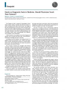
Definition 10 (Object-Oriented Transformation System). An object-oriented transformation system TS = (DSig, St, CG, m) consists of an objectoriented data space signature DSig = (DS , Fun, OS , Attr, Meth, Constr ), a static part St = ((St s )s∈DS , (fSt )f ∈Fun ) with carrier sets St s and partial data functions fSt , a control transition graph CG = (CS , T , in, id ) and a transition graph morphism m: CG → DDSig , such that St ⊆ m(cs)|DS ,Fun for all cs ∈ CS \ {in}. The class of all object-oriented transformation systems is denoted by OOTS. (See Fig. 5 for an example.)
OOTS
DSig= data sorts: Bool functions: true: −> Bool false: −> Bool object sorts: Class attributes: lnk: Class −> Class methods: Class.meth(Class):Bool
obj1
obj2 obj3
call meth ( obj1 ,obj3 )
obj1
St= StBool ={true,false} trueSt =true false St =false
obj2 obj3
asslnk( obj1 ,obj3 )
obj1
obj2
ret meth (true) obj1
obj3
obj2 obj3
Fig. 5. Object-oriented transformation system
The object-oriented transformation systems according to this definition differ from the object-oriented instantiations of transformation systems in [5] mainly in three regards: A static part is not explicitly considered in [5], object configurations are modeled as families of algebras instead of single algebras, and associations are modeled explicitly to allow the handling of multiplicities and visibilities. Now, that we have a formal notion of models of object-oriented systems, we will define some viewpoint specification techniques in the sense of Def. 2 for these models in the next section.
4
Viewpoints on Object-Oriented Transformation Systems
In this section we want to define viewpoint specification techniques for objectoriented systems, where we will mainly consider techniques with relation to the UML (see [8]). According to the formal framework presented in Sect. 2 and especially Def. 2, we will consider the object-oriented transfomation systems as the common model class (i. e. Mod = OOTS) and for each viewpoint specification technique VP we will define an abstract model class SemVP and a view ViewVP : OOTS → SemVP , which abstracts object-oriented transformation systems into this class. The viewpoints can be organized according to the layers of the integration paradigm for data type and process modeling techniques of Ehrig and Orejas, presented in [18] and equipped with a formal model in [19], where we add a layer for the system structure, which is only implicitly considered by signatures in [19]. An overview of the layers of the integration paradigm, the viewpoints and corresponding viewpoint specification techniques is given in Table 1. Table 1. Layers of the integration paradigm and corresponding viewpoints Layer Structure Data Types Data States and Transformations Processes
Viewpoint System Structure Static Data Types Method Effects
Specification Technique UML Class Diagrams Algebraic Specifications OCL Pre- and Post-Conditions
Method Structures Action Language Object Protocols Statechart Diagrams Object Interaction Sequence Diagrams
In the following subsections we will examine the viewpoints “System Structure”, “Static Data Types”, “Method Effects” and “Method Structures”. The specification of object protocols by statechart diagrams and their consistency with the viewpoints treated here has been sketched on a conceptual level in [4]. The relations between statechart and sequence diagrams were investigated in [5], based on a transformation system semantics for both techniques. We will not define the formal syntax for each of the viewpoint specification techniques. The alignment of this work with meta-modeling using typed graphs for the formal definition of visual languages as presented e. g. in [20], however, seems to be a valuable line of future research. 4.1
System Structure
In this viewpoint we want to model the system structure, where we choose to demand the whole structure to be given in one viewpoint specification, i. e. there has to be a complete class diagram for the entire system. This is a methodological
decision to ensure syntactical consistency. If all the viewpoints could add entities to the system, inconsistencies due to different namings in different viewpoints could arise. By demanding a single specification of the whole structure, these inconsistencies can be detected by checks against this specification. As a running example we will consider classes of linked lists and list elements. The structure of this example is specified by the class diagram in Fig. 6. Lists contain a reference to the first element of the list, while each list element has a reference to the next one and carries a natural number as date, which is why we need natural numbers as static data type. Additionally, there is a static data type for Boolean values, which are used as return values for some of the methods. Data types are marked by the UML stereotype >, which is used for data types without object identities in [8]. We only consider those methods needed in the following occurences of the example, i. e. constructors for both classes, a method insert to insert natural numbers into the list and a method setNext to manipulate the reference next of list elements.
first 0..1
List create() insert(n: Nat):Bool
ListElem content: Nat create(n: Nat) setNext(elem: ListElem):Bool
Nat zero():Nat succ(Nat):Nat
next 0..1
Bool true():Bool false():Bool
Fig. 6. Specification by class diagram
The semantics of a class diagram can be given by a data space signature, which contains all entities declared in the diagram. We can abstract from everything except the structure by simply projecting the signature out of an objectoriented transformation system. The structure of the running example is given by the view in Fig. 7.
first: List −> ListElem content: ListElem −> Nat next: ListElem −> ListElem constructors: create():List create(Nat):ListElem methods: List.insert(Nat):Bool ListElem.setNext(ListElem):Bool
DSig= data sorts: Nat, Bool functions: zero: −> Nat Sem Struct succ: Nat −> Nat true: −> Bool false: −> Bool object sorts: List, ListElem
attributes:
ViewStruct
OOTS
DSig
St
Fig. 7. System structure of the example
The following definition summarizes, how class diagrams can be used as a viewpoint specification technique in the sense of Def. 2, where we also give the induced model function according to Def. 2. Definition 11 (System Structure Viewpoint Specification Technique). The class VSpecStruct of system structure specifications is given by class diagrams with an induced data space signature DSig(CD ) ∈ OODSig for each class diagram CD ∈ VSpecStruct . The class SemStruct := OODSig of system structure models is given by the class of all object-oriented data space signatures. The semantic function Sem Struct: VSpecStruct → P(SemStruct ) is given by the one-element set Sem Struct (CD) := {DSig(CD)} for all CD ∈ VSpecStruct . The view View Struct : OOTS → SemStruct is given by View Struct (TS ) := DSig for all TS = (DSig, St, CG, m) ∈ OOTS. This leads to the model function Mod Struct : VSpecStruct → P(OOTS) given by Mod Struct (CD) := {(DSig, St, CG, m) | DSig = DSig(CD)} for all CD ∈ VSpecStruct . 4.2
Static Data Types
This viewpoint is concerned with the data sorts and functions, which are static for all states of the system. To realize the seperation of concerns, all other viewpoints should be defined loosely w. r. t. the data types. Since the UML does not provide means to specify static data types, we use algebraic specifications as viewpoint specification technique. We only need equational specifications (see [21]) for our example, but more sophisticated logics could also be used. In our running example, we want the static data types to be Boolean values and natural numbers. We use an ad-hoc notation based on the OCL for algebraic specifications as shown in Fig. 8. Since there are no equalities, which have to hold in these small examples, we just use initial constraints to forbid unspecified equalities and unreachable data elements in the algebras. For larger applications of the framework the integration of some mature algebraic specification framework like Casl (see [22]) or the set-theoretic notation Z (see [23]) would be useful extensions. The semantics of such a specification are all pairs of signatures and algebras, where the signature includes the signature of the algebraic specification and the reduct of the algebra satisfies the specification. For equations as in our example this means, that for all assignments of the variables in the equations both sides of the equations are evaluated to the same elements.
context Nat initial: zero=zero for all n: Nat succ(n)=succ(n)
context Bool initial: true=true false=false
Nat zero():Nat succ(Nat):Nat
Bool true():Bool false():Bool
Fig. 8. Specification by algebraic specification
Since all object-oriented transformation systems are required to have a static part, we can use a projection of the data type part of the signature and this static part as view of the system. The static data type view of our example can be seen in the view in Fig. 9.
Sig= data sorts: Nat, Bool functions: zero: −> Nat succ: Nat −> Nat Sem Static true: −> Bool false: −> Bool
A= ANat = {0,1,2,...} ABool = {t,f} zeroA= 0 succA(n) = n+1 trueA= t falseA= f
ViewStatic
OOTS
DSig
St
Fig. 9. Static data types of the example
We use the following notions for algebraic specifications. Let AlgSig be the class of all algebraic signatures and let AlgSpec be the class of all algebraic specifications, i. e. signatures with corresponding equations. The class Alg(Sig) contains all algebras for the signature Sig. Algebraic specifications as viewpoint specification technique in the sense of Def. 2 are given by the following definition. Definition 12 (Static Data Type Viewpoint Specification Technique). The class VSpecStatic of static data type specifications is given by algebraic specifications with data type signature Sig(AS ) ∈ AlgSig for each algebraic specification AS ∈ VSpecStatic = AlgSpec. The class SemStatic := {(Sig, A) | Sig ∈ AlgSig, A ∈ Alg(Sig)} of static data type models is given by the class of pairs of algebraic signatures and corresponding algebras. The semantic function Sem Static : VSpecStatic → P(SemStatic ) is given by the set Sem Static (AS ) := {(Sig, A) | Sig(AS ) ⊆ Sig, A|Sig (AS ) |= AS }
for all AS ∈ VSpecStatic . The view View Static : OOTS → SemStatic is given by View Static (TS ) := ((DS , Fun), St) for all TS = (DSig, St, CG, m) ∈ OOTS with data space signature DSig = (DS , Fun, OS , Attr, Meth, Constr ). This leads to the model function Mod Static : VSpecStatic → P(OOTS) given by Mod Static (AS ) := {(DSig, St, CG, m) ∈ OOTS | Sig(AS ) ⊆ DSig, St|Sig(AS ) |= AS } for all AS ∈ VSpecStatic . 4.3
Data Effects of Methods
This viewpoint deals with the effects the execution of methods has on the data states. For pre- and post-conditions we assume a signature of the entities used in the conditions and that pre-conditions are formulated over the input variables of the corresponding operation, while the post-conditions use the output variables. The effects of the method insert are specified by the OCL constraint in Fig. 10. Namely, a list element with the given natural number should be inserted as the new first element of the list, and the former first element should follow the new element. context List::insert(n: Nat) post: self.first.next = self.first@pre self.first.content = n
List insert(n: Nat):Bool
first ListElem 0..1 content: Nat
next 0..1
Fig. 10. Specification by OCL constraint
We formalize this by relations between input data states with input parameters and output data states with output parameters. Figure 11 shows the abstraction of one execution of the method insert, where the signature and the static part are omitted for readability reasons. Such an abstraction is included in the effect relation for each execution of insert in the model. The formalization of OCL pre- and post-conditions as viewpoint specification technique for method effects can be found in the following definition. Definition 13 (Method Effect Viewpoint Specification Technique). The class VSpecEffect of method effect specifications is given by OCL pre- and post-conditions with an induced data space signature DSig(OCL) ∈ OODSig for each OCL specification OCL ∈ VSpecEffect , pre-constraints Pre(OCL, op) and post-constraints Post(OCL, op) for each OCL specification OCL ∈ VSpec Effect and each operation op ∈ Meth ∪ Constr .
Sem Effect
Relinsert ={
,
, (obj 1 ,23) ,
obj1
obj1
obj2 : 23
, true ,
}
ViewEffect
OOTS obj1
callinsert (obj 1 ,23)
obj1
obj1
obj2 : 23
ret insert ( true )
obj1
obj2 : 23
Fig. 11. Data effects of method insert
The class SemEffect := { (DSig, Rel) | DSig ∈ OODSig, Rel = (Rel op )op∈Meth∪Constr , Rel op ⊆ {(A, in, B, out) | A, B ∈ CS DSig , in ∈ Aw , out ∈ Bs } for op ∈ Meth w→s or op ∈ Constr w→s } of method effect models is given by the class of pairs of data space signatures and families of effect relations. The semantic function Sem Effect : VSpecEffect → P(SemEffect ) is given by the set Sem Effect (OCL) := { (DSig, Rel) | DSig(OCL) ⊆ DSig, ∀(A, in, B, out) ∈ Rel op : (A, in) |= Pre(OCL, op) ⇒ (B, out) |= Post(OCL, op) } for all OCL ∈ VSpecEffect . The view View Effect : OOTS → SemEffect is given by View Effect (TS ) := (DSig, Rel) for all TS = (DSig, St, CG, m) ∈ OOTS, where the effect relations in Rel are generated by taking from each execution of an operation op in TS the data state and the input parameters of the call action and the data state and the return parameter of the corresponding return action. This leads to the model function Mod Effect : VSpecEffect → P(OOTS) which assigns a set of transformation systems TS = (DSig, St, CG, m) to each OCL specification OCL ∈ VSpecEffect , where this set contains all transformation systems of the following kind. The signature DSig has to be a subsignature of the signature of the OCL specification DSig(OCL). For each occurence of an operation op ∈ Meth ∪ Constr in the models TS the state before the call has to satisfy Pre(OCL, op) and the state after the return has to satisfy Post(OCL, op). 4.4
Structure of Methods
While the last viewpoint abstracts from the concrete means, by which a method realizes its effects, this viewpoint, vice versa, abstracts from the effects and extracts the structure of methods.
Since this view is very close to programming and code generation, an abstract imperative language, such as the action languages of the UML, is appropriate to specify this viewpoint. The structure of the method insert is specified in Fig. 12, where we use a simple ad-hoc notation as action language. An exact treatment of the action language concept given in the UML should be given in a future refinement of the framework.
context List::insert(i: Int) var elem=ListElem.createListElem(i) elem.setNext(self.first) set self.first=elem return true
List insert(n: Nat):Bool
first
ListElem
0..1 content: Nat
next 0..1
Fig. 12. Specification by action language
The semantics of such an action language expression is given by all labeled transition systems, whose complete traces (traces ending with a final state) are also complete traces of the bevaviour specified by the expression. This means, that a method may only deadlock, if the deadlock is also allowed in the labeled transition system of the action language expression. The abstract models contain labeled transition systems for each method, which are derived from the transformation systems by forgetting the state labels and hiding the structure of called methods. Due to limited space, we cannot give the slightly complicated fully formal treatment of this construction here. In Fig. 13 a part of the structural view of the method insert is shown, where all executions of the methods are merged into a single trace in the abstract view, because the actions are the same and the differences are only visible in the data states, which are forgotten by the view.
Sem Method
LTSinsert =
i callcreate ( x 1)
callsetNext ( r 1 , self.first)
ass first ( r 1 )
ret insert ( true)
ViewMethod
callinsert (...)
callcreate ( x 1)
callsetNext ( r 1 , self.first)
ass first ( r 1 )
ret insert ( true)
callinsert (...)
callcreate ( x 1)
callsetNext ( r 1 , self.first)
ass first ( r 1 )
ret insert ( true)
OOTS
Fig. 13. Structure of method insert
Next, we show how the idea of an action language can be formalized in the framework of object-oriented transformation systems.
Definition 14 (Method Structure Viewpoint Specification Technique). The class VSpecMethod of method structure specifications is given by action language expressions with an induced data space signature DSig(AL) ∈ OODSig for each action language specification AL ∈ VSpecMethod . Moreover, we assume that each action language expresion for an operation op induces a labeled transition system LTS (AL, op). The class SemMethod := { (DSig, LTS ) | DSig ∈ OODSig, LTS = (LTS op )op∈Meth∪Constr , LTS op = (S, Act DSig , →, i), →⊆ S × Act DSig × S, i ∈ S } of method structure models is given by the class of pairs of data space signatures and labeled transition systems for each method with initial states i corresponding to the beginnings of the methods, i. e. the states before the call actions. States that have no further states to be accessed by the → relation can only be reached by relation entries mapped with retop . The semantic function Sem Method: VSpecMethod → P(SemMethod) is given by the set Sem Method(OCL) := {(DSig, LTS ) | DSig(AL) ⊆ DSig, LTSop ⊆ LTS (AL, op)} for each AL ∈ VSpecMethod , where the second condition means that all traces for an operation op in the models have to be part of the labeled transition system induced by the specification LTS (AL, op) and the traces in the model are only allowed to deadlock if this deadlock is also specified LTS (AL, op). The view View Method : OOTS → SemMethod is given by View Method (TS ) := (DSig, LTS ) for all TS = (DSig, St, CG, m) ∈ OOTS, where LTS = (LTSop )op∈Meth∪Constr is calculated by collecting all occurences of op in TS and gluing the corresponding traces in LTSop . The data states are omitted in this construction. This leads to the model function Mod Method : VSpecMethod → P(OOTS) which assigns sets of transition systems TS = (DSig, St, CG, m) to all specifications AL ∈ VSpecMethod , where we require that DSig(AL) ⊆ DSig holds and for each occurence of an operation op ∈ DSig(AL) the trace between the starting state and the final state of the operation has to be part of LTS (AL, op) and the execution of the method may only stop, if we have a corresponding deadlock in LTS (AL, op).
5
Consistency of Object-Oriented Transformation System Specifications
In this section we show how the consistency of a system specification, consisting of viewpoint specifications can be checked. We will present the explicit constructions needed for the consistency check for the viewpoint specification techniques presented in the previous section. Further viewpoints could be added
and integrated in a similar way. The check is done by step-wise composition of the canonical models for the viewpoint specifications, where this process either yields a canonical model for the whole system specification or fails due to some inconsistencies, which can be characterized by the exact reason, why one of the compositions was not possible. Moreover, we give some syntactical conditions, when a canonical composition is possible, which could then be checked by development tools. 5.1
Construction of Canonical Models for Viewpoint Specifications
In this section we define the construction of canonical models for the four viewpoint specification techniques introduced in the last section. We will use these constructions to develop a corresponding construction of a cannonical model for system specifications using these four viewpoints. We can also understand this construction as an intra viewpoint consistency check, since the construction is only defined and sound w. r. t. the specification, if the corresponding viewpoint specification is free of contradictions. In the case of the sample four viewpoints we do not have such inconsistent specifications, and thus the canonical constructions become total mappings from the viewpoint specifications to the common domain of object-oriented transformation systems and the result is always a model of the specification. In the case of the structure viewpoint the canonical model for a given class diagram CD is given by the following object oriented transformation system CanStruct (CD) = (DSig(CD), StCD , CGCD , mCD ), where DSig(CD) is the data space signature induced by the class diagram according to Def. 11. The static part StCD is the empty algebra ∅. The control graph CGCD is given by the data space induced by the data space signature, DDSig(CD) , according to Def. 9 and mCD is an identical morphism in the category of transition graphs. This means control graph and data space are equal in this case. Since this model uses the data space signature DSig(CD), Def. 11 implies CanStruct (CD) ∈ ModStruct (CD) for all CD ∈ VSpecStruct . The canonical model for a given algebraic specification AS is given by CanStatic (AS ) = (DSig(AS ), TAS , CGAS , {∗ 7→ in}) with CGAS = ({∗}, {id (∗)}, ∗, id ). The data space signature DSig(AS ) of the model is the induced signature Sig(AS ) given by the specification according to Def. 12. The static part of the transformation system is given by the quotient term algebra TAS of the given specification AS . The control graph CGAS contains a single state, which is mapped by mAS to the initialization state of the data space in. This canonical model construction has a trivial dynamic part, i. e. the control graph is discrete, and thus, not controls any behaviour. The interesting part of the model is limited to TAS . Since this model uses the signature induced by AS and the static part TAS fulfills AS by construction, we have by Def. 12 that CanStatic (AS ) ∈ ModStatic (AS ) holds for all AS ∈ VSpecStatic .
In the method effect viewpoint we construct the canonical model for a given specification OCL as follows CanEffect (OCL) = (DSig(OCL), ∅, CGOCL , mOCL ), where DSig(OCL) is the data space signature induced by the specification OCL according to Def. 13. The control graph CGOCL is a restriction of the induced data space DDSig(OCL) of DSig(OCL). This restricted graph only contains return transitions that are compatible with the relation Rel (OCL, op) for each op ∈ DSig(OCL). Thus, it is ensured that all runs of op in the model fulfill the specified post-conditions if the pre-conditions were valid in the state the operation was called at. The morphism mOCL : CGOCL → DDSig(OCL) is the obvious inclusion. Since this model uses the data space signaure DSig(OCL) and all operation runs fulfill the pre- and post-conditions, we can conclude by Def. 13 that CanEffect (OCL) ∈ ModEffect (OCL) for all OCL ∈ VSpecEffect . The canonical model for a given action language specification AL is given below CanMethod (AL) = (DSig(AL), ∅, CGAL , mAL ), where DSig(AL) is the data space signature of the action language specification according to Def. 14. The control graph CGAL is a gluing of the labeled transition systems of the action language specification LTS (AL, op) for all operations op ∈ DSig(AL). The final states of completed traces of these labeled transition systems are again connected with the labeled transition sytems LTS (AL, op) for all operations op ∈ DSig(AL). The morphism mAL maps complete traces into the data space, such that the labels of the transitions in the control graph are the same as the names of the actions they are mapped to. The model uses the data space signature DSig(AL) and the single method runs satisfy LTS (AL, op) for all operations op ∈ DSig(AL) by construction of CGAL . Thus, we have by Def. 14 that CanMethod (AL) ∈ ModMethod (AL) is valid for all AL ∈ VSpecMethod . 5.2
Structural Consistency
Structural consistency, sometimes also called syntactical consistency, ensures, that all viewpoint specifications exclusively use entities, which are already declared in the structural viewpoint. This is checked by composing each of the other canonical models with the canonical model of the class diagram, so that the resulting models all have the same data space signature, namely the signature induced by the class diagram. These constructions fail, if there are entities in the specifications of data effects or method structures, respectively, which are not declared in the structure specification. Thus, we obtain the general consistency condition DSig(VSpec) ⊆ DSig(CD) for all viewpoint specifications VSpec for the viewpoints method effect and method structure. The static data type is examined in the next section. Assuming this condition we are able to lift the other viewpoint specifications to
the larger data space signature of the system structure specification which is a further step in the construction of a canonical model for a system specification. We will realize this lifting by pullbacks in the category of transition graphs.
CG’VSpec m’VSpec
DDSig(CD)
CG VSpec (PB)
mVSpec
V
DDSig(VSpec)
Fig. 14. Structural consistency
Given a viewpoint VP and the canonical model for a viewpoint specification VSpec as constructed in Sect. 5.1, CanVP (VSpec) = (DSig(VSpec), ∅, CGVSpec , mVSpec ). In Fig. 14 we see the control graph CGVSpec and the data space DDSig(VSpec) of such a given viewpoint specification VSpec, connected by the morphism mVSpec . Since we assumed DSig(VSpec) ⊆ DSig(CD) we can define a morphism V between the data space of the structure viewpoint specification and the data space DDSig(VSpec) by VCS (A) = A|DSig(V Spec) for all A ∈ CSDDSig(CD) and VT (t) = t ∈ TDDSig(VSpec) (V (A), V (B )), if t ∈ DSig(V Spec), and τ , else. Now we 0 for VP = Effect, Method . On an intuitive can construct the pullback CGVSpec 0 level, this means that CGVSpec collects and identifies those states and transitions of DDSig(CD) and CGVSpec which have a common image in DDSig(VSpec) . We can use the result of the pullback to define composed transition systems for specification techniques that do not affect the static part. 0 0 CanStruct,VP(CD, VSpec) = (DSig(CD), ∅, CGVSpec , mVSpec ), 0 is the result of the pullback construction. This definition directly where CGVSpec implies that the composed models are a model for both, the class diagram and the other viewpoint specification technique, if the viewpoint specifcation technique does not affect the static part and if it allows its models to use a larger signature. Since this is the case for the viewpoints method effect and method structure, we can formulate the following lemma.
Lemma 2 (Syntactic Integration). Given a class diagram CD and a viewpoint specification VSpec for another viewpoint VP ∈ {Effect, Method } we have CanStruct (CD) ∈ ModStruct (CD) ∧ CanVP (VSpec) ∈ ModVP (VSpec) ⇒ CanStruct,VP (CD, VSpec) ∈ ModStruct (CD) ∩ ModVP (VSpec).
Proof. The constructed model CanStruct,VP (CD, VSpec) uses the data space signature DSig(CD), and thus, we can conclude by Def. 11 for all class diagrams CD ∈ VSpecStruct and all VSpec ∈ VSpecVP that the constructed model is a model for the class diagram, i. e. CanStruct,VP(CD, VSpec) ∈ ModStruct (CD). Since the pullback construction does not add any new states or transitions to 0 CGVSpec in CGVSpec , nor removes any, we can conclude that the composed model still fulfills VSpec. t u 5.3
Restriction According to the Static Part
In the next step of our construction we will constrain the control graph of the canonical model for the system structure viewpoint constructed before, such that only data states that fulfill the static part specification are accessed. For the canonical model CanStruct (CD) = (DSig(CD), ∅, CGCD , mCD ) we define the restriction as follows: 0 0 ResAS (CanStruct (CD)) = (DSig(CD), St, CGAS , mAS ), 0 where the new control graph CGAS is given by 0 CSCGAS = CSCGCD \ {c | mCDCS (c) 6|= AS } and 0 TCGAS = TCGCD \ {T (c, d ) | mCDCS (c) 6|= AS ∨ mCDCS (d ) 6|= AS }
0 is the obvious restriction of mCD , which was the identic morphism. Inand mAS tuitively, we remove all states and the corresponding transitions from the control graph that are mapped to algebras in the data space that do not fulfill the static part St. Note that this construction is defined only if the signature of the static part specification DSig(AS ) is also contained in the signature of the structural specification DSig(CD). If this is the case, the construction above ensures that the result is a model of both specifications.
Lemma 3 (Static Part Restriction). Given an algebraic specification AS ∈ VSpecStruct and a class diagram CD ∈ VSpecStruct. If DSig(AS ) ⊆ DSig(CD) holds, then we have ResAS (CanStruct (CD)) ∈ ModStruct (CD) ∩ ModStatic (AS). Proof. The constructed model uses the data space signature DSig(CD), it is a model of the class diagram CD. Moreover, the model has the static part SP , and thus, is a model of the algebraic specification AS . t u 5.4
Integration of Method Effect and Structure
In this section we want to integrate the results of the previous constructions. Again, we will use pullbacks in the category of transition graphs. Given a canonical model for a class diagram CD after the restriction of the control graph with respect to a given algebraic specification AS , according to Sect. 5.3, 0 0 ResAS (CanStruct (CD)) = (DSig(CD), St, CGAS , mAS ),
and given a canonical model for a method effect specification OCL which has been lifted to the signature of the class diagram CD, according to Sect. 5.2, 0 0 CanStruct,Effect (CD, OCL) = (DSig(CD), ∅, CGOCL , mOCL ).
CG AS,OCL m’’ OCL
CG’AS
CG’OCL (PB)
m’OCL
m’AS
DDSig(CD )
Fig. 15. Integration of Static Part and Method effect
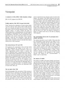
Figure 15 shows the control graph of the lifted canonical model for the method 0 effect viewpoint (CGOCL ) and the control graph of the restricted canonical model 0 for the structure specification (CGAS ). The construction of the canonical models ensures that both control graphs are mapped to the same data space, namely the data space induced by the data space signature of the class diagram, DDsigCD . Thus, we can construct the resulting control graph as the pullback CGAS ,OCL of the given control graphs. This construction removes all states and connected transitions from the control graph of the lifted method effect model that are mapped to data states that do not fulfill the static data type specification AS . We can use the resulting control graph to define an integrated transformation system. CanStruct,Static,Effect(CD, AS , OCL) = (DSig(CD), St, CGAS ,OCL , mAS ,OCL ), 0 00 where mAS ,OCL is defined as mAS ◦ mOCL . If we remove states and transitions from the control graph of the canonical method effect model, it might happen that we loose a state which was needed to fulfill the method effect specification, i. e. a state which was reached by a return action of an operation op ∈ DSig(OCL) and which satisfied Post(OCL, op). If this deleted state was the only state with these two properties reachable from the state where the operation was called and this starting state satisfies Post(OCL, op), then this state should violate the static part specification as well, because otherwise, the resulting model would violate the method effect specification.
Lemma 4 (Integration of the Method Effect). Given a class diagram CD ∈ VSpecStruct, an algebraic specification AS ∈ VSpecStatic , and a method effect specification OCL ∈ VSpecEffect . Now we have CanStruct,Static,Effect(CD, AS , OCL) ∈ ModStruct (CD) ∩ ModStatic (AS ) ∩ ModEffect (OCL),
if the method effect specification OCL ensures that a final state of an operation run satisfies Pre(OCL, op) ∧ SP if Post(OCL, op) ∧ SP was valid at the starting state. Proof. Since the model uses the data space signature induced by CD and the static part specified in AS , it satisfies CD and AS by construction. Moreover, the construction above ensures, that only complete traces of operation runs are removed and that the remaining ones satisfy the effect specification OCL. t u In the next step we integrate the signature lifted canonical model into the last constructed model. Given an integrated canonical model of a class diagram, an algebraic specification and a method effect specification as defined above CanStruct,Static,Effect(CD, AS , OCL) = (DSig(CD), St, CGAS ,OCL , mAS ,OCL ) and given a signature lifted model of a method structure specification 0 0 CanStruct,Method(CD, AL) = (DSig(CD), ∅, CGAL , mAL ).
CG AL,OCL,AL m’’ AL
(PB)
CG’AL m’AL
CG AS,OCL mAS,OCL DDSig(CD ) Fig. 16. Integration of Method Effect and Mehtod Structure
0 Again, the control graphs of the two models (CGAS ,OCL , CGAL ) are mapped to the same data space DDsig(CD) by construction. This situation is depicted in Fig. 16. Thus, we are able to construct the pullback CGAS ,OCL,AL . This construction deletes all states and the corresponding transitions of the control graph of the lifted canonical model for the method structure specification which are mapped to data states that either do not satisfy the static part specification or that do not satisfy the method effect specification. We can now define the integrated canonical model for the four used viewpoint specification techniques.
CanStruct,Static,Effect,Method(CD, AS , OCL, AL) = (DSig(CD), St, CGAS ,OCL,AL , mAS ,OCL,AL ), 00 where mAS ,OCL,AL = mAS ,OCL ◦ mAL . In order to decide, whether this transformation system is a model of the method structure specification AL we have to check, whether we removed transitions from the control graph that were needed to finish an operation run. Moreover, Post(OCL, op) has to be ensured in all
operation runs that fulfilled Pre(OCL, op) when they were called. More general, if we remove unique return transitions of an operation op ∈ DSig(AL) then also the corresponding call transition should origin in a state not satisfying St or OCL which then would be removed by the restriction as well. Lemma 5 (Integration of Method Structure Specifications). Given a system specification (CD, AS , OCL, AL) ∈ SSpec. Now we have CanStruct,Static,Effect(CD, AS , OCL) ∈ ModStruct (CD) ∩ ModStatic (AS ) ∩ ModEffect (OCL), ⇒ CanStruct,Static,Effect,Method(CD, AS , OCL, AL) ∈ ModStruct (CD) ∩ ModStatic (AS ) ∩ ModEffect (OCL) ∩ ModMethod (AL), if the operation runs specified by AL preserve the static part SP and realize the effect specification OCL. Proof. The model CanStruct,Static,Effect,Method(CD, AS , OCL, AL) is in the model class ModStruct (CD) ∩ ModStatic (AS ) ∩ ModEffect (OCL) by the assumption of the lemma and by the fact that the construction above only removes complete operation run traces, and thus, does not affect the validity of CD, AS , and OCL. Moreover, the model fulfills the specification AL, since all method runs with a structure different from the specified one are removed. t u If we now combine the conditions for the the nested model classes, we can fomulate the following theorem. Theorem 1 (Consistency of System Specifications). A system specification (CD, AS , OCL, AL) ∈ SSpec is consistent, if the following conditions are satisfied: 1. All entities used in AS , OCL and AL are declared in CD, 2. OCL preserves the static part specified by AS . 3. AL only uses attributes and data functions, which are ensured to be defined in the corresponding data states, 4. the method specifications in AL realize the pre- and post-conditions in OCL and preserve the static part. In this case a canonical system model can be constructed by step-wise composition of the canonical viewpoint models. Proof. We start with the canonical models given in Sect. 5.1 which turned out to be in the model class of the corresponding specification. Using this, we can apply Lem. 2 for the integration of the cannonical models for CD, OCL, and AL. Thus, we obtain two signature lifted models that are in the corresponding shared model class. Lemma 3 is applicable because of condition 1 from above and yields an integrated model of CD and AS which satisfies both specifications. Using assumption 2 and Lem. 4, we obtain a model which satisfies CD, AS , and OCL. Finally, assumptions 3 and 4 together with Lem. 5 imply the stated consistency. t u
6
Conclusion
This paper presents a constructive consistency check for object-oriented specifications. In contrast to [4], where we introduced the idea of a constructive consistency check in an informal and example-oriented manner, we give a formal definition of the single construction steps in this paper. This is done by the definiton of a common semantic domain, object-oriented transformation systems. Based on this domain we define formal views for the semantic domain equipped with suiting specification techniques. In order to be able to build larger software specifications, we want to develop structuring means for our semantic domain and the different specification techniques in the near future. Such compostion operations should preserve the consistency of the parts that are connected. An analogous procedure is planned for development and refinement relations, which are inter alia applied in [24] in this volume, where a concept for specification components is introduced. Such refinements should preserve the consistency of the system specifications. Acknowledgements: This work is partially supported by the German DFG (German Research Council) project IOSIP (Integration of object-oriented software specification techniques and their application-specific extension for industrial production systems on the example of automobile industry) within the DFG Priority Programme “Integration of Software Specification Techniques for Applications in Engineering”. We would like to thank Hartmut Ehrig and Martin Große-Rhode and the referees for their valuable comments on previous versions of the paper.
References 1. Finkelstein, A., Kramer, J., Nuseibeh, B., Finkelstein, L., Goedicke, M.: Viewpoints: A Framework for Integrating Multiple Perspectives in System Development. International Journal of Software Engineering and Knowledge Engineering 2 (1992) 31–58 2. International Organization for Standardization: ISO 10746:1998 – Information Technology – Open Distributed Processing – Reference Model. (1998) 3. Ehrig, H., Große-Rhode, M.: Integration von Techniken der Softwarespezifikation f¨ ur ingenieurwissenschaftliche Anwendungen. Informatik Forschung und Entwicklung 16 (2001) 110–117 4. Schr¨ oter, G., Braatz, B., Ehrig, H., Klein, M., Bengel, M.: Semantische Konsistenz viewpoint-orientierter Modellierungstechniken am Beispiel der Produktionsautomatisierung. atp – Automatisierungstechnische Praxis (2004) To appear. 5. Große-Rhode, M.: Semantic Integration of Heterogeneous Software Specifications. Monographs in Theoretical Computer Science. Springer (2004) 6. Tenzer, J.: A Formal Semantics of UML Class Diagrams based on Transformation Systems. Forschungsbericht 2001/09, Fachbereich Informatik, TU Berlin (2001) 7. Parnitzke, D.: On Formal Semantics of Object Systems with Data and Object Attributes. Forschungsbericht 2001/05, Fachbereich Informatik, TU Berlin (2001) 8. Object Management Group: Unified Modeling Language – Version 2.0 (UML 2.0). (2004) Available from http://www.omg.org/.
9. Milner, R.: Communication and Concurrency. International Series in Computer Science. Prentice Hall (1989) 10. Reisig, W.: Petri Nets. Volume 4 of Monographs on Theoretical Computer Science. Springer (1985) 11. Rozenberg, G., ed.: Handbook of Graph Grammars and Computing by Graph Transformations, Volume 1: Foundations. World Scientific (1997) 12. International Organization for Standardization: ISO 8807:1989 – Information Processing Systems – Open Systems Interconnection – LOTOS – A Formal Description Technique Based on the Temporal Ordering of Observational Behaviour. (1989) 13. Chandy, K.M., Misra, J.: Parallel Program Design – A Foundation. AddisonWesley (1988) 14. Object Management Group: Unified Modeling Language – Version 1.5 (UML 1.5). (2003) Available from http://www.omg.org/. 15. Goguen, J.A., Burstall, R.M.: Institutions: Abstract Model Theory for Specification and Programming. Journal of the Association for Computing Machinery 39 (1992) 95–146 16. Ehrig, H., Große-Rhode, M.: Functorial Theory of Parameterized Specifications in a General Specification Framework. Theoretical Computer Science 135 (1994) 221–266 17. Orejas, F., Pino, E.: On the Integration of Heterogeneous Specifications. In Ehrig, H., Damm, W., Desel, J., Große-Rhode, M., Reif, W., Schnieder, E., Westk¨ amper, E., eds.: Integration of Software Specification Techniques for Applications in Engineering. Number 3147 in Lecture Notes in Computer Science. Springer (2004) 18. Ehrig, H., Orejas, F.: Integration Paradigm for Data Type and Process Specification Techniques. Bull. EATCS (1998) 90–97 19. Ehrig, H., Orejas, F.: A Conceptual and Formal Framework for the Integration of Data Type and Process Modeling Techniques. In: Graph Transformation and Visual Modeling Techniques (GT-VMT 2001). Number 50,3 in Electronic Notes in Theoretical Computer Science, Elsevier (2001) 20. Bardohl, R., Ehrig, H., de Lara, J., Taentzer, G.: Integrating Meta-Modelling Aspects with Graph Transformation for Efficient Visual Language Definition and Model Manipulation. In Wermelinger, M., Margaria-Steffen, T., eds.: Fundamental Approaches to Software Engineering (FASE 2004). Number 2984 in Lecture Notes in Computer Science, Springer (2004) 214–228 21. Ehrig, H., Mahr, B.: Fundamentals of Algebraic Specification 1 – Equations and Initial Semantics. Volume 6 of Monographs on Theoretical Computer Science. Springer (1985) 22. Mosses, P.D., ed.: Casl Reference Manual. Number 2960 in Lecture Notes in Computer Science. Springer (2004) 23. Spivey, J.M.: The Z Notation: A Reference Manual. Prentice Hall (1992) 24. Braatz, B., Klein, M., Schr¨ oter, G., Bengel, M.: A Formal Component Concept for the Specification of Industrial Control Systems. In Ehrig, H., Damm, W., Desel, J., Große-Rhode, M., Reif, W., Schnieder, E., Westk¨ amper, E., eds.: Integration of Software Specification Techniques for Applications in Engineering. Number 3147 in Lecture Notes in Computer Science. Springer (2004)