Session S2D PROJECT MANAGEMENT AND VERIFICATION THE KEY PROBLEMS OF STUDENT CHIP DESIGN COURSES Jörn Jachalsky1 , Mark B. Kulaczewski2 , and Peter Pirsch3 Abstract With the intention to attract more students to specialize in the fields of microelectronics and to create a learning environment in which students are trained in so called soft skills the Institute of Microelectronic Circuits and Systems started to offer project-oriented courses. In this one semester course students are introduced to all steps of a standard cell based design flow and thus learn how to design, implement, and verify an ASIC using state-of-the-art software tools. The complex design task is partitioned into equally important sub-modules, which are closely connected. Thus only by successful cooperation and coordination the students can accomplish the task until the end of the semester. The lessons learned from the first run of the course are that next to the common problems, which come along with the usage of hardware description languages and the handling of new complex design tools, project management and thorough and successful design verification are the key problems of those student chip design courses. Measures taken to overcome these problems are presented in this paper. Index Terms Chip design, design verification, project management, student courses.
INTRODUCTION In the last few years it could be noticed that the electrical engineering students’ focus of interest shifted slightly from microelectronics to software engineering, what might be a side effect of the great success of the Internet. Additionally, as complex engineering and research tasks can only be performed in teamwork, the necessity arises – reflected by the growing industry demand – that graduates do not only have specialized knowledge of electrical engineering topics but also have a basic training in so-called soft skills, which include communication and presentation skills and the ability to efficiently work in teams. Therefore, the Institute of Microelectronic Circuits and Systems (IMS) developed a concept for a project-oriented course that deals with the mentioned problems. Since 1999, the IMS has offered a project-oriented course called "ChipDesign" [1], which was attended by 76 students over the last three years. On the initiative of the IMS, a more general version of the concept, which keeps the idea to set an additional course focus on the soft skills, but is not restricted to the fields of microelectronics, was introduced into the electrical and 1 2 3
computer engineering curriculum of the University of Hannover in 2001.
OBJECTIVES The target group for the course ChipDesign is graduate level students. The course was not planned to be a replacement for conventional theory-oriented lectures. Instead, it was intended to help to deepen, intensify, and link the knowledge that students gained in those lectures. Furthermore, it should attract students to specialize in fields of microelectronics and to attend additional corresponding lectures. The main objectives of this course can be summarized as: • Introduce students to a state-of-the-art design flow for integrated circuits and create an industry-like working environment. • Give an opportunity to gain practical experience and to link theory and practice. • Create a learning environment in which students are trained in soft skills: Learn to work in teams and improve communication, organization, coordination, and presentation skills.
COURSE DESCRIPTION Within ChipDesign students are introduced to all steps of a standard cell based design flow and thus learn how to design, implement, and verify an ASIC from specification over implementation to physical layout using state-of-the-art software tools. Thus there is a certain similarity to other chip design courses [2]-[3], although they differ in the size of the project and the number of students attending it. Additionally, the courses offer a different approach towards chip design – full-custom design, FPGA -based design and standard cell based design – and thus support a different design flow. The goal of the course ChipDesign is to completely design an ASIC in one semester, i.e., 15 weeks. Content The content of the course covers the following topics. It should be noted that each topic is introduced in a special class that lasts about 90 to 120 minutes. • Overview of modern chip design techniques and introduction to a standard cell based design flow for integrated circuits.
Jörn Jachalsky, University of Hannover, Institute of Microelectronic Circuits and Systems, Hannover, Germany,
[email protected] Mark B. Kulaczewski, University of Hannover, Institute of Microelectronic Circuits and Systems, Hannover, Germany,
[email protected] Peter Pirsch, University of Hannover, Institute of Microelectronic Circuits and Systems, Hannover, Germany,
[email protected]
0-7803-7444-4/02/$17.00 © 2002 IEEE November 6 - 9, 2002, Boston, MA 32 nd ASEE/IEEE Frontiers in Education Conference S2D-12
Session S2D • • • •
Hardware description language (HDL) Verilog, design of synchronous logic, use of Verilog-XL from Cadence®. Logic synthesis, use of Design Compiler™ from Synopsys®. Physical layout, backend tools from Cadence®: e.g., Silicon Ensemble® and Diva®. Presentation techniques, preparation guidelines for talks and presentations.
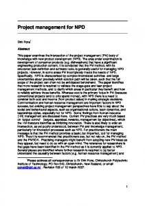
A positive side effect of ChipDesign is that it can be seen as an important step to efficiently integrate HDLs in the electrical and computer engineering curriculum [4]. The Project In the last three years the project was to design a Least Cost Router (LCR), which finds the cheapest telephone provider for long distance calls with respect to time and day and also dials the telephone number extended by the selected provider access code. The LCR consists of a keyboard, a LC-display, a serial interface for data upload, a loudspeaker to output dual tone multi-frequency (DTMF) signals, and the central control unit ASIC (CCU), which was to be designed by the students. Figure 1 shows a block diagram of the LCR. CCU
Keyboard
KeyboardController
NumberBuffer
Serial Interface
InterfaceController
Control- & Search-FSM
Synthesizer
Loudspeaker
DisplayController
Display
Timer
Memory
cooperation. For further motivation it was announced that the ASIC would be manufactured, provided that a fully verified design was achieved at the end of the course. In correspondence with the objectives for this course, a further idea was to let the students autonomously perform the project management. As it is difficult to fairly assess the contribution of the individual student within the groups, there is only a pass-fail option for this course. Realization Next to the special classes mentioned above, additional practical classroom presentations were given to introduce the software tools used. Additionally, group meetings were held to discuss problems of the project. Starting from a basic specification of their sub-module, the students had to work out a detailed version including an exact timing specification of the interfaces. Thereby they had to define and specify timing diagrams. These specifications had to be discussed and agreed upon with the other student groups. Subsequently each group had to describe its sub-module in Verilog and develop a verification strategy to sufficiently verify the function. Furthermore, the logic synthesis of each sub-module had to be done. Towards the end of the course, the students had to deal with the tasks of sub-module integration, global synthesis, and global verification. Moreover, they had to do the physical layout of the verified gate-level netlist that was done in special group sessions guided by teaching assistants. For further functional verification, the students were offered an in-circuit-emulation of their design using a Quickturn® M250 (Figure 2).
FIGURE. 1 BLOCK DIAGRAM OF THE LEAST COST ROUTER
To reduce the complexity of the design task, the design of the CCU was partitioned into sub-modules that were assigned to seven work packages of almost the same complexity. Each sub-module was described in a basic specification, which was handed out to the students at the beginning of the course. The basic specification of the submodules contained the description of the functionality and the definition of in- and output signals (but not the timing specification). The students were assigned to seven groups and each group had to work on one work package. Due to the complexity of a full design flow and the fact that some of the students were not completely familiar with these new subjects, each group was advised by two teaching assistants to maintain continuous access to help if necessary. As the complete design was split into sub-modules that were all equally important for the overall success of the project, the students could only accomplish the design task by successful
FIGURE. 2 I N -CIRCUIT EMULATION WITH QUICKTURN ® M250
0-7803-7444-4/02/$17.00 © 2002 IEEE November 6 - 9, 2002, Boston, MA 32 nd ASEE/IEEE Frontiers in Education Conference S2D-13
Session S2D Infrastructure and Resources Since 2000 all students attending the course had continuous access to a computer laboratory with eight SUN Ultra10 Workstations with 1 GB of memory each and a laser printer. Due to numerous other research projects, the IMS has a fully supported industrial design flow, which was employed in this course. For design, simulation, and manufacturing, a 0.6µm standard cell library from Austria Mikro Systeme International AG (AMS) was used. For project organization and information a web server was installed. It also served to publish class related documents and software documentation.
LESSONS LEARNED FROM FIRST YEAR Despite the students’ efforts, the first run of the course did not result in a verified design. Consequently, no ASIC was manufactured at the end of the course. The main reason was identified as the students’ problem to perform an autonomous project management and their underestimation of the effort that is necessary to make a thorough and successful verification. Incidentally, it must be pointed out that initially the teaching assistants involved did not correctly assess the students’ problems with the verification. Although the students had only minor difficulties to cooperate within the groups, there were some significant problems in the cooperation between groups. It could be observed that in some crucial design phases, e.g., the exact timing specification of the interfaces, there was only insufficient communication between the groups. Consequently, binding agreements, which were necessary to guarantee a correct functioning of all sub-modules after the integration, were missing. Therefore, the sub-modules seemed to function as required in the specification, but there were some interface incompatibilities that caused the complete system not to work correctly. A further consequence of the insufficient communication between the groups was that it was hard for the students to track the progress of the work and to determine the actual status of the project. Concerning the project management the students had problems to work out a schedule for their tasks. This included difficulties to set reasonable project milestones and deadlines. Also the assignment of responsibility for new arising tasks – the integration of the sub-modules, the verification of the complete system and the global synthesis – was hard and time-consuming. So precious time was wasted to find someone to be in charge of the new tasks. In the end there was no time left for necessary design changes of the sub-modules, when the students encountered problems and difficulties while verifying the complete system. In a final evaluation at the end of the course the students noted that they had expected more guidance concerning the project management and the verification process. To recap, the lessons learned from the first run of the course are that project management and thorough and
successful design verification are the key problems that are to be solved for a successful project.
CHANGES AND M EASURES INTRODUCED As a consequence, for the second and the third run of the course a tighter focus was set on teamwork issues and the verification process. Although the idea was kept to allow an autonomous project management by the students, it was intended to offer more support and a certain degree of guidance. In a first step the basic specification, which was handed out to the students, was completely revised. Thereby, it was discussed to fully specify the interfaces between the submodules to overcome the problems faced in the first run of the course. But this was not put into practice, as the specification of the interface timing was seen as a good measure to force the student groups to start cooperating. Therefore a special meeting was introduced to the course in which the students had to specify all interfaces between the sub-modules. A positive side effect of this meeting was that the students got to know each other right at the beginning of the course and then knew whom to contact when problems with other sub-modules occurred. To further support a better contact between students, they were randomly assigned to the groups. Next to continuous group meetings, now mandatory project meetings with all groups were held at least once a week. These project meetings were used to discuss the current status of the project with all groups to guarantee a constant flow of information. Furthermore, the students had to work out a schedule for their tasks as well as to discuss and agree on project milestones and deadlines in these meetings. Also a constant review of the schedules was done and it was checked whether all groups held the agreed deadlines. In case of delays the groups had to explain why they did not hold the deadlines. Then the schedules had to be adjusted. The project meetings were guided by the teaching assistants to offer support and guidance if necessary. Moreover, the meetings were thought to be good forum to coordinate the work between the groups and to assign the responsibilities for new arising tasks, especially integration of the sub-modules and verification of the complete system. To deal with these new tasks the students formed new groups. The students were encouraged to write down all agreements and decisions made and to publish the documents on the project web server. So all results of the meetings and arrangements were accessible by the students as well as the teaching assistants. The documentation of the important design and verification decis ions contributed to the successful cooperation between the groups. To circumvent and to solve the problems, which the students had with the verification in the first run of the course, a special class about design verification was
0-7803-7444-4/02/$17.00 © 2002 IEEE November 6 - 9, 2002, Boston, MA 32 nd ASEE/IEEE Frontiers in Education Conference S2D-14
Session S2D introduced to the course. This class dealt with principles and methodologies of verification. Furthermore, guidelines for the verification process were given, e.g., the students should implement so-called self-checking testbenches to verify their designs. Additionally, a special meeting was held to let the students coordinate their verification efforts. With the introduced measures it was possible to manufacture a fully verified ASIC at the end of the second and third run of this course. The actual manufacturing of the students’ design took place after the semester. In a special session in the following semester, each student was presented with a working sample, a printed-circuit board, and a parts list of the system. Figure 3 depicts the CCU ASIC, which was manufactured after the course in the summer semester 2001, and Figure 4 shows the corresponding LCR demonstrator.
principles and theory of physical layout and verification, whereas the second one concentrates on the practical aspects of physical layout and introduces the software tools used. TABLE I Week 1 2 3 4 5 6-10 11 12-13 14 15
SPECIAL CLASSES AND MEETINGS Class or Event Meeting Introduction to chip design Verilog HDL Interface specification Verification Project meeting Synthesis Project meet ing Physical layout I Verification coordination and project meeting Project meeting Physical layout II Project meeting Project meeting Presentation techniques Plenary session with group presentations
To further support the design decisions, which the students had to make for the synthesizer module, a javabased simulator was developed for the third run of the course. This simulator helps to find suitable design parameters – e.g. word width and shift range – and allows a first validation whether the chosen parameters meet the requirements of the DTMF specification. The simulator can be run as a java-applet in common web-browsers (Figure 5).
FIGURE. 3 T HE CCU ASIC
FIGURE. 5 JAVA -BASED SIMULATOR FOR SYNTHESIZER MODULE
RETROSPECT AND FUTURE ACTIVITIES FIGURE. 4 T HE LEAST COST ROUTER DEMONSTRATOR
The now established schedule for all special classes and the introduced additional meetings is shown in Table I for the course offered in 2001. To achieve a good coupling of the front-end and the back-end design, the physical layout class was split into two classes. The first one, which is held one week after the class about logic synthesis, deals with the
Although the students had a lot of work to do within one semester, the course got a good response and received good grades in a student evaluation. Moreover, it must be pointed out that the course ChipDesign heavily depends on the contribution of a large number of teaching assistants. Table II shows the number of students attending the course over the last three years. It also contains the number of teaching assistants involved in the course.
0-7803-7444-4/02/$17.00 © 2002 IEEE November 6 - 9, 2002, Boston, MA 32 nd ASEE/IEEE Frontiers in Education Conference S2D-15
Session S2D TABLE II
[2]
Chen, T., "From System Design to IC Design in 14 Weeks – Teamwork Makes it Possible," IEEE Transactions on Education, Vol. 36, No. 1, February 1993, pp. 137-140.
[3]
Purdy, C.N., "Significant microelectronics systems design experience for a heterogeneous class of CS, CE and EE students," 1997 International Conference on Microelectronic Systems Education (MSE 1997), July 1997, pp. 143-144.
[4]
Chang, K. C., "Including HDL and Synthesis in the EE and CSE Digital Design Curriculum," 1997 International Conference on Microelectronic Systems Education (MSE 1997), July 1997, pp. 125126.
STUDENTS IN THE COURSE
Year 1999 2000 2001
Students attending the course 28 28 20
Groups 7 7 6
Teaching assistants 14 14 12
For the summer semester 2002 it is intended to offer the design of a LCR as the project of the course ChipDesign for the last time. Therefore, the IMS has started to work on the realization of a new project that has to fulfill the following requirements: • It should be an ASIC. • It must be possible to partition the design into reasonable sub-modules of almost the same complexity. • The time to completely design the ASIC should not exceed one semester. • The application should be of some interest. Therefore it is planned to design a microcontroller that can control either a small meteorological station or an electronic timetable information system for the local public transportation system.
CONCLUSION Since 1999 the IMS has offered the project-oriented course ChipDesign. This course is meant to attract students to specialize in the fields of microelectronics and to create a learning environment in which students are trained in socalled soft skills. The common goal of all students attending this course is to design, implement, and verify an ASIC. The lessons learned from the first run of the course, which did not result in a working design, are that project management and thorough and successful design verification are the key problems to be solved for student chip design courses. The measures taken to overcome these problems of the first run of the course are presented in this paper. The success of the second and third run was mainly based on a tighter focus on the design verification and a stricter project management, which was partly supported and guided by the involved teaching assistants.
ACKNOWLEDGMENT This course was partly funded by the Ministry for Science and Culture of the state of Lower Saxony, Germany, as part of the project "PROMISE". The authors acknowledge the contribution and participation of all those who helped to realize this course.
REFERENCES [1]
Kulaczewski, M. B., Zimmermann, S., Barke, E., Pirsch, P. "CHIPDESIGN - A Novel Project -oriented Microelectronics Course," 2001 International Conference on Microelectronic Systems Education (MSE 2001), June 2001, pp. 71-72.
0-7803-7444-4/02/$17.00 © 2002 IEEE November 6 - 9, 2002, Boston, MA 32 nd ASEE/IEEE Frontiers in Education Conference S2D-16