Two orthopaedic examples (knee prosthesis, hip prosthesis) are ... automatically calculated in the finite element mesh with a custom-made software. ... PATRAN software is used for the pre-processing and ABAQUS software for the stress.
Short lecture notes on biomechanics of implants :
THE LONG-TERM BEHAVIOUR OF HUMAN JOINTS WITH ORTHOPEDIC PROSTHESES: FINITE ELEMENT MODELS Lalaonirina R. Rakotomanana
Key words: Orthopaedic implants, Bone-implant interface, Bone adaptation. Abstract. In the short-term, clinical problems after non-cemented total joint replacement are caused by initial instability of implant (high relative micro motions of the implant with respect to the host bone) which may lead to late aseptic loosening. Failure is mainly due to the inhibition of interface bone ingrowth and to the change of bone into a fibrous tissue encapsulating the implant anchorage. In the long-term, varying of bone density results in varying stiffness and strength of bone. Significant long-term bone loss gives porotic spongious bone which cannot be relied upon to well support orthopaedic prosthesis particularly for loading joints as knee and hip. The purpose of this work is to present a theoretical framework with numerical methods to investigate the short term and long term fixation of various orthopaedic prostheses with or without cement. The bone tissue is assumed non-homogeneous and anisotropic. The adaptation rate of the bone relative density is related to a mechanical stimulus by a piece-wise linear equation, including an equilibrium zone. For numerical solving, an Euler semi-implicit time integration is implemented. The system of equations being stiff, an adaptive stepsize control based on the technique of step doubling is implemented. Two orthopaedic examples (knee prosthesis, hip prosthesis) are presented. The results show the coupling effects between bone stress adaptation and implant instability. In the short-term behavior, assumption of perfect bonding at the interfaces may drastically restrict finite element model abilities. For the long-term analysis, the evolution of bone density is essential for any long-term study of orthopaedic implants and for their designs.
1
Lalaonirina R. Rakotomanana.
1
INTRODUCTION
After total joint replacement, early failure of non cemented implants, designed for ensuring biological fixation, is thought to be initiated by the initial instability of implant and then the lack of bone ingrowth, particularly for femoral component after Total Hip Replacement and for tibial component after Total Knee Replacement. Late failure of cemented implants, designed for inter-locking mechanical fixation, is commonly related to wear particle debris resulting from the cement fracture and fragmentation due to high stress and enhanced by the interface micromotions. High amount of wear particle debris is suspected to induce periprosthetic osteolysis, probably due to debris migration along the bone-implant interface. Many factors are then involved in the safety of orthopedic implant anchorage such as the bone quality and the implant design and interface. Few numerical models have been developed to analyze in a synthetic way the relative influence of each of them and to quantify the coupling effects between adaptive bone properties and the bone-cement-implant mechanics. The purpose of this paper is to present a theoretical framework with numerical methods to investigate the short term and long term fixation of various orthopedic prostheses with or without cement. Two examples are presented to illustrate the model ability: fixation of tibial component after TKR and fixation of femoral component after THR. 2 ROLE OF BONE PROPERTIES AND INTERFACE MECHANICS 2.1 Total Knee Replacement Aseptically loosening of the tibial component is one of the failure causes after TKR1. Analysis of interfacial membranes surrounding aseptically loose tibial component has shown the presence of polyethylene, metallic and cement debris. These debris are produced by wear between femoral component and articulating tibia and by wear and fragmentation of cement. Loosening generally occur at the bone-cement interface for the cemented prostheses2. Among various factors, uneven distribution of stress transfer between the implant and tibia constitutes the major cause of aseptic loosening3. Bone properties also play an important role in the biomechanics of tibial component anchorage. In the short-term, seek of bone quality for implant leaning is pursued by the care of tibial component positioning and the tibial resection. Indeed, porotic spongious bone can accelerate the sinking and tilting of tibial plateau. In the long-term, accounting for continuously varying bone density may not be neglected since magnitude of bone stiffness may be four times when the density is doubled4. 2.2 Total Hip Replacement Two mechanisms are mainly sources of clinical complications after non-cemented THR: the initial instability of femoral stem and the proximal bone resorption. In the short-term, the initial stability of the stem is a prerequisite for ensuring the bone ingrowth5 and then is
2
Lalaonirina R. Rakotomanana.
necessary to obtain a safe fixation. In the long-term, the proximal bone resorption following the bone under-stressing, called stress-shielding6, is thought not limiting directly the longevity of femoral stem. However, decrease of bone density results in a decrease of elastic modulus and strength of both the compact and spongious bone. Furthermore, analysis of stress and micromotions in presence of bone remodeling has shown the coupling effects between stress shielding and stem instability7. 3
NUMERICAL MODEL CHARACTERISTICS
For modeling the bone tissue and bone-implant interface, we have developed finite element models including the anisotropic and non-homogeneous bone properties together with bone mechanical adaptation7. The geometry and the non-homogeneous distribution of the bone density is reconstructed from a series of CT-scanner slices of bone, and the density field is automatically calculated in the finite element mesh with a custom-made software. The bone-implant interface is modeled by unilateral frictional contact8, which allows microdebonding and micro-slipping at the interfaces. For every pair of particles potentially in contact, the unilateral contact model is defined by the classical Signorini relationships. We also assume a (dry) Coulomb friction at the interfaces. The features of the bone adaptation model have been developed in a previous work9. The local evolution of bone density is controlled by a stress stimulus field, which is based on the existence of a homeostatic equilibrium zone. The mechanical stimulus, which controls the bone adaptation, is the Hill plastic yield criterion function of the bone10. The choice of this stimulus is based on the hypothesis that bone damage drives the bone remodeling. PATRAN software is used for the pre-processing and ABAQUS software for the stress analysis. For each example, we evaluate the initial instability and the bone-implant stress transfer immediately after implantation, the evolution of bone density surrounding the stem and finally the post-remodeling stability of the implant. 4
FIXATION OF TIBIAL COMPONENT AFTER “TKR”
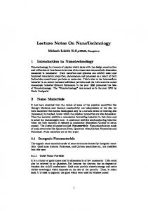
Lower limb misalignment, soft tissue imbalance and the bone resection before implantation are determinant factors for aseptically loosening of the tibial component. Tibial component failure may be partially because of long-term modification of bone quality beneath the tibial component. In this example, we compare the relative influence of bone adaptation vs. lower limb misalignment on the tibial component stability and on the stress transfer immediately after implantation and after bone remodeling. The finite element mesh was reconstructed from a series of CT scanner slices of a cadaver tibia (Figure 1). Both the spongious and the compact bone are assumed to have transverse isotropic symmetry. The fixation of cemented Total Condylar tibial prosthesis is analyzed with the model. Implant position accounts for a maximal cortical bearing with postero-medial and antero-lateral support and for a satisfactory patello-femoral tracking. Bone-cement
3
Lalaonirina R. Rakotomanana.
interface is modeled with unilateral frictional contact (friction coefficient: 1.)11. No relative micro motions are allowed at the implant-cement interface. Applied loads are defined in order to correspond to mean values for daily activity. Two loading conditions are simulated. (1) A total axial load of 5000 N (six times B.W.) is applied symmetrically on the medial and lateral compartments with in addition the patella ligament force (2500 N, 10° from tibial axis) and the collateral ligament forces (medial: 400N; lateral: 300N). (2) A non-symmetrical loading conditions with 1/3 on the lateral and 2/3 on the internal compartment with patellar and collateral ligament forces.
Figure 1. Three-dimensional mesh of the bone-implant system (right), reconstructed from a series of CT scanner slices of a cadaverous proximal tibia (left).
For the symmetrical loading, the regions of highest pressure and shear stress are located under the bearing surfaces condyles. After a 1-year remodeling, there is a global resorption of 13% localized at the plateau peripheral regions. Densification is noticed under the condyles (Fig. 2). The bone remodeling for symmetrical loading does not significantly modify the distribution of the micro slipping of the tibial implant with respect to the tibial bone. For varus conditions, bone-implant interfacial highest stresses are also found under the two condyles. Debonding [µm]
Slipping [µm]
Pressure [MPa]
Friction [MPa]
S - initial
27
60
7.9
2.0
S - final
30
63
8.1
2.0
V - initial
36
57
10.4
2.4
V - final
37
61
10.5
2.5
Table 1 Peak values of micro-motions, stresses at the bone-cement interface and peak values of cement von Mises stress for symmetric (S) and varus (V) loading conditions – immediately after implantation (Initial) and after bone adaptation (Final)
4
Lalaonirina R. Rakotomanana.
After bone adaptation, the global resorption is 15% mainly in the external compartment. Micro slipping distribution is not modified after bone remodeling. For both loading conditions, cement stress concentration appears under the condyles’ center. But the lower limb misalignment (varus) induces a significant augmentation of cement stress (20%) which occurs under the internal compartment. The simulated long-term (1-year survival of the prosthesis) change of bone density is quite conforming to clinical investigations, typically a loss of bone density of 1.5% per month. However, effects of bone remodeling on the anchorage quality are found modest compared to the more deleterious influence of lower limb misalignment (Table 1).
Figure 2. Distributions of bone relative density in a proximal human tibia for the symmetrical loading. (Left) Before implantation of tibial component, reconstructed from CT-scanner slices. (Right) After bone adaptation equilibrium, which corresponds to 1-year survival of the orthopaedic implant.
5
FIXATION OF FEMORAL STEM AFTER “THR”
After non-cemented THR, the stem initial instability and the proximal bone resorption depend on numerous factors as interface properties, material stiffness, shape and size of the implant12, 13. For custom-made stems, two basic concepts exist for the development of their shape: the stem size determines either a tendency to a cortical leaning or a tendency to a spongious leaning of the stem. This example compares the effects of the stem size on the initial stability after non-cemented THR, the proximal femoral bone loss and the postremodeling stability of the stem. The finite element model is reconstructed from the CT-scanner data of a real patient. A custom-made stem, designed for this patient, is then numerically inserted in the femur according to usual surgical techniques: normal reconstruction of the offset femoral head, neutral valgus positioning and natural anteversion restoration. The bone-implant interface is modeled as frictional contact (coefficient: 0.2). Two stem sizes are compared. (1) The lower size corresponds to a leaning of the stem on spongious bone in the medullar canal (SL:
5
Lalaonirina R. Rakotomanana.
spongious leaning). (2) The upper size corresponds to an optimal fitting of the femoral stem inside the internal endosteal surface of the femur (CL: cortical leaning). The designs of all stems are based on the principle of optimal fitting criteria. Daily activity is averaged by using loading conditions corresponding to single leg stance including major muscular forces (gluteus maximus, gluteus medius, psoas) 13,14.
Figure 3. Distributions of bone relative density in a proximal human femur after bone remodeling, which corresponds to 2-years survival of the implant. (Left) Spongious leaning, and (Right) Cortical leaning.
For the short-term, micro-motions are slightly greater for the cortical leaning than for the spongious leaning. For both cases, the locations of high micromotions are approximately the same: highest debonding at the stem tip and highest slipping both at the stem tip and at the medial proximal zones. However, the regions where high slipping occurred have greater surface area for the SL stem. The magnitude of contact pressure and frictional shear stress are comparable for the two designs. Maximum stress values (pressure, friction) are greater for the CL design. Maximum shear stresses occur at the medial proximal regions (Table 2). Debonding [µm]
Slipping [µm]
Pressure [MPa]
Friction [MPa]
SL - initial
28
68
34.1
5.9
SL - final
26
70
27.2
4.2
CL - initial
35
79
40.9
7.6
CL - final
22
77
30.1
5.7
Table 1. Maximum values of interfacial micromotions and stresses for cortical (CL) and spongious leaning (SL).
6
Lalaonirina R. Rakotomanana.
For the long-term situation, a proximal resorption, a densification in the lateral proximal, and a distal cortical hypertrophy are observed for both designs (Figure 3). The CL design presents more femoral proximal resorption than the SL design. Micromotion and stress magnitudes are different after bone remodeling. However, the location of their peaks varies slightly. The most sensitive change is the maximum debonding for the CL design. Accordingly, the decrease of contact pressure magnitude is also observed either for the CL and the SL designs. This example shows that the initial stability and the bone-implant stress transfer depend sensibly on the mode of leaning (cortical or spongious). Micromotions remain sensibly at the same order level before and after bone remodeling. In summary, the results could provide information for supporting the choice of the stem size in regards of stem initial stability and its long-term fixation. 6
CONCLUSION
For the short-term situation, the need of an appropriate interface model is clearly demonstrated by the magnitude of debonding and of shear micromotions registered in the examples. Interface discontinuity may bring new insight for better understanding initial instability of orthopedic implants which is correlated with the debonding and shear micromotions at the bone-implant interface (cemented or not). Assumption of perfect bonding at the interfaces could restrict drastically finite element model abilities. For the long-term analysis, introduction of non-homogeneity of bone is required to evaluate more precisely interfacial micromotions and stresses. Moreover, evolution of density is an essential parameter for any long-term study of orthopedic implants. Acknowledgement. The examples presented in this paper were obtained in the course of research conducted with Dr A Terrier, Dr N Ramaniraka (Orthopaedic Hospital, Lausanne). REFERENCES [1] Windsor RE, Scuderi GR, Moran MC, Insall JN. Mechanisms of failure of the femoral and tibial components in total knee arthroplasty, Clin. Orthop. 248, 15-20 (1988). [2] Walker PS. Human joints and their artificial replacements. Ed. by Charles C. Thomas, Bannerstone, Illinois (1977). [3] Hsu HP, Garg A, Walker PS, Spector M, Ewald FC. Effect of knee component alignement on tibial load distribution with clinical correlation, Clin. Orthop. 248, 135-144 (1989). [4] Rice JC, Cowin SC, Bowman JA. On the dependence of the elasticity and strength of cancellous bone on apparent density. J. Biomechanics, 21, 155-168 (1988). [5] Pilliar RM, Lee JM and Miniatopoulos C. Observations of the effects of movement on bone ingrowth into porous-surfaced implants. Clin. Orthop. 208, 108-6 (1986). [6] Korovessis P, Piperos G, Michael A. periprosthetic bone mineral density after Mueller
7
Lalaonirina R. Rakotomanana.
and Zweymueller total hip arthroplasties, Clin. Orthop. 309, 214-221 (1994). [7] Rakotomanana LR, Terrier A, Ramaniraka NA, Leyvraz PF. Anchorage of orthopaedic prostheses: influence of bone properties and bone-implant mechanics. In Synthesis in Bio Solid Mechanics, ed. by P. Pedersen and M P. Bendsøe, Kluwer Academic Publishers, 5566 (1999). [8] Curnier A., He Q.-C. and Klarbring A. Continuum mechanics modelling of large deformation contact with friction. In Contact Mechanics, ed. M Raous et al., Plenum press New York, 145-158 1995. [9] Terrier A, Rakotomanana, LR, Ramaniraka, NA, Leyvraz PF. Adaptation models of anisotropic bone. Comp Meth Biomech Biomed Eng, 1, 47-59 (1997). [10]Rakotomanana LR, Terrier A, Leyvraz PF. Anisotropic bone adaptation models: comparison and application to orthopaedic implants, in Computer Methods in Biomechanics and Biomedical Engineering, Middleton J et al., ed., Gordon and Breach, 95-104 (1996). [11]Rakotomanana LR, Leyvraz PF, Curnier A, Meister JJ, Livio JJ. Comparison of tibial fixations in total knee arthroplasty: an evaluation of stress distribution and interface micromotions, The Knee, 1, 91-99 (1994). [12]Callaghan JJ, Fulghum CS, Glisson RR, and Stranne SK. The effect of femoral stem geometry on interface motion in uncemented porous-coated total hip prostheses. Comparison of straight-stem and curved-stem designs. J. Bone Joint Surg. 74-A, 839-848 (1992). [13]Kröger H, Venesma P, Jurlevin J, Miettinen H, Suomalainen O, Alhava E. Bone density at the proximal femur after Total Hip Arthroplasty, Clin. Orthop. 352, 66-74 (1998). [14]Davy DT, Kotzar GM, Brown RH, Heiple KG, Goldberg WM and Burstein AH. Telemetric Force measurements across the hip after total hip arthroplasty. J. Bone Joint Surg. 70A, 45-50 (1988). [15]Ramaniraka NA, Leyvraz PF, Rakotomanana LR, Rubin PJ, Zysset PK. Micromotions at the bone-stem interface during a gait cycle after cementless total hip replacement: influence of the stem design and loading level, Hip International 6, 2, 51-58 (1996).
8