Simple Median Based Information Fusion in Wireless ... - IEEE Xplore
Recommend Documents
AbstractâEnterprise big-data analytics requires data from diverse sources to be ... decisions: Prescriptive rather than mere predictive analytics is needed, which ...
AbstractâEnterprise big-data analytics requires data from diverse sources to be fused and harmonized after which it becomes useful for mining interesting ...
University of Toronto. 10 King's College Road, Toronto, Canada. {azadeh ... proximity sensors, radio frequency (RF) badges, and Wireless. Local Area Network ...
College Park, Maryland, uSA. Phone: (301) 405 5323. Fax: (301) 314 9269. ... Chandler, Arizona, uSA. $EVWUDFW The rapid evolution of electronic products ...
Oct 2, 2014 - [3], and methods of multilevel security [4]. A current trend that can enable all of these services is cloud computing. Cloud com- puting as defined ...
Apr 26, 2016 - Paolo Braca, Member, IEEE, Ryan Goldhahn, Gabriele Ferri, Member, IEEE, and Kevin D. LePage. Abstractâ Surveillance in antisubmarine ...
VIDEO WIRELESS COMMUNICATION BASED ON HIGH SPEED 8 Ã 8 MIMO-OFDM. SYSTEM. Hiroki Iwaizumi, Masahiro Sugitani, Baiko Sai, Hiroshi Tsutsui ...
WIRELESS UNs ireless local area net- works emerged from near disaster in the mid-'90s to become one of today's driving wireless tech- nologies, delivering ...
AbstractâIntentional attack incurs fatal threats on modern networks by paralyzing a small fraction of nodes with highe
communication technology and high speed electronics have made it .... AN ANALYTICAL MODEL FOR INFORMATION RETRIEVAL IN WIRELESS SENSOR ...
Dec 17, 2013 - Thus, it could be an online controller for a self-healing power grid to deal with ... wide area measurement system (WAMS) in the power grids, ..... 4.1 Case study with the whole test system .... ModernGrid_Final_v2_0.pdf.
model of the MeSH thesaurus by the identification of the semantic relations between concepts. The results of the extraction model serve to mapping a query in ...
AbstractâThe recent proliferation of Location-Based Services (LBSs) has ... In such a context, Wireless Local Area Network (WLAN) positioning is a particularly ...
AbstractâIt is generally believed harmful to have transmis- sion errors in the wireless communications. The high decoding complexity of dense parity check ...
Abstract—Hyperspectral imagery contains a wealth of spectral and spatial information that can improve target detection and recognition performance.
With the development of the micro-electro-mechanical system (MEMS) technology, wireless communication,. Routing in wireless sensor networks (WSNs) is very.
May 7, 2014 - held in Tampa, Florida. The weather will be warm ... for Emerging Tech- nologies, which was .... cess, as he describes how the new logo for the.
May 7, 2014 - We have a full and varied issue for ... issue in December of last year and is a ... John Wood ([email protected]) is with Maxim. Integrated ...
communication devices, antennas play a paramount role. ... Digital Object Identifier 10.1109/MMM.2013.2240896 .... Microsoft and Apple supporting this.
Charles E. Perkins. Prasant Mohapatra. IEEE Communications Magazine ⢠November 2007. 62 ireless mesh networks (WMNs) are expected to be a.
mart homes link computers to every- ... A smart home assumes wntrol of devices and coordinates ... physical layer protocols can support delay-sensitive data.
Jan 30, 2015 - THE NEXT GENERATION MOBILE COMMUNICATIONS AND .... Networks Inc., Seattle, WA, USA, one of the leading mobile network providers ...
Index TermsâWireless measurement, embedded LC resonant sensor, HTCC technology, passive temperature sensor. I. INTRODUCTION. IN ORDER to prevent ...
t is well known that a technology becomes ... In common with ather systems, the technology growth ... The articles in this special issue cover three user scenar-.
Simple Median Based Information Fusion in Wireless ... - IEEE Xplore
Median based sensor fusion function named D function. It is shown that the proposed D function satisfies the lipschitz condition. Paper also presents some of the ...
2012 International Conference on Computer Communication and Informatics (ICCCI -2012), Jan. 10 – 12, 2012, Coimbatore, INDIA
Simple Median Based Information Fusion in Wireless Sensor network Deepti Singhal, Rama Murthy Garimella International Institute of Information Technology, Hyderabad, India - 500 032, [email protected], [email protected]
Abstract—The accuracy of a system is measured by the deviation of the system’s results from the actual results. Information fusion deals with the combination of information from same source or different sources to obtain improved fused estimate with greater quality or greater relevance. As larger amount of sensors are deployed in harsher environment, it is important that sensor fusion techniques are robust and fault-tolerant, so that they can handle uncertainty and faulty sensor readouts. The sensor nodes in Wireless Sensor Network (WSN) are constrained with computation and communication resources, and efforts are required to increase the performance measures of the network. Thus sensor fusion techniques should be simple with less computation complexity. In this paper we propose a novel Median based sensor fusion function named D function. It is shown that the proposed D function satisfies the lipschitz condition. Paper also presents some of the ideas which can open new areas for research in fusion problem. Index Terms - Wireless Sensor Network, Sensor Fusion, Me- dian.
I. I NT RODUCT ION
data fusion using large multiple sensor agents, its network structure and performance is discussed in paper [3]. The terminology related to fusion of data from multiple sources is not uniform. Different terms have been adopted, usually associated with specific aspects that characterize the fusion. Before we understand the techniques for sensor fusion, it is important to understand the relationship among the fusion related terminologies. The term data fusion and information fusion can be used interchangeably. Information fusion is the merging of information from disparate sources with differing conceptual, contextual and typographical representations. It is used for consolidation of data from unstructured or semi-structured resource. On the other hand, multi-sensor integration is a slightly different term in the sense that it applies information fusion to make inferences using sensory devices and associated information (e.g., from database systems) to interact with the environment. According to [4] Multi-sensor integration is the synergistic use of information provided by multiple sensory devices to assist in the accomplishment of a task by a system; and multisensory fusion deals with the combination of different sources of sensory information into one representational format during any stage in the integration process. Multi-sensor integration is a broader term than multi-sensor fusion. Thus, sensor/multi-sensor fusion is fully contained in the intersection of multi-sensor integration and information/data fusion. Data aggregation defines another subset of information fusion that aims to reduce the data volume (typically, summarization), which can manipulate any type of data/information, including sensory data. Figure 1 depicts the relationship among
2012 International Conference on Computer Communication and Informatics (ICCCI -2012), Jan. 10 – 12, 2012, Coimbatore, INDIA • Fail-stop failures, in which a failed abstract sensor We may regard a sensor an entity through which we are can be detected able to view a physical property. In general the physical • Arbitrary Failures with bounded inaccuracy property is evolving continuously in time and value. However, • Arbitrary failures, in which an abstract sensor can the sensor only provides us with a picture of the process: fail arbitrary. typically the output of a sensor is reduced to a single crisp value. The output of a sensor includes Entity-Name, Spatial The fault tolerant fusion algorithm works with the Location, Time Instant (t), Measurement (y), and Uncertainty assumption that no more than f sensors are faulty out of the in the measurement (∆y [5]. Thus the sensor observation total n sensors. Table I summarizes the maximum number of is an interval as (y − ∆y, y + ∆y). This kind of interval TABLE I fusion is first introduced by Marzullo in [6], and is known M A X I M U M FAU LT Y S E N S O R S as abstract sensor fusion. An abstract sensor is a sensor that reads a physical parameter and gives out an abstract interval Failure Model fmax
−
n
estimate which is a bounded and connected subset of the real line. This means an abstract sensor A will give the interval of real numbers [lA , uA ], where lA < uA ; lA is the lower bound and uA is the upper bound of the interval. Abstract sensors can be classified into correct sensors and faulty sensors. A correct sensor is an abstract sensor whose interval estimate contains the actual value of the parameter being measured. Otherwise, it is a faulty sensor. A faulty sensor is tamely faulty if it overlaps with a correct sensor, and is wildly faulty if it does not overlap with any correct sensor [7].
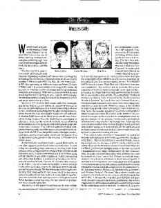
All the solutions discussed in this section, work with the assumption of maximum number of faulty sensors with bounded inaccuracy. Thus one can assume fmax = (n − 2)/2. So, typically the physical parameter is a crisp value, like This means that with (n − 2)/2 faulty sensors algorithm will in the case of temperature sensing, the value of temperature work properly. Let I , I , . . . , I be the interval estimates 1 2 n sensed is a crisp value. The process of arriving at the abstract from n abstract sensors, and maximum f of them could be interval estimate from the physical parameter or adding the faulty. Four functions were developed representing four uncertainty, can be done in two ways: milestones in this area discussed in [7], these four functions (a). By adding equal left and right tolerance to the sensed are shown in figure 2. crisp value / physical parameter. (b). By adding unequal left and right tolerance to the sensed I1
crisp value / physical parameter.
I2 I3 I4
Thus in sensor fusion problem can be considered as a problem of giving a fused (interval or crisp) estimate of the intervals generated with equal left and right tolerance and unequal left and right tolerance, as well as defining the architectural technique of fusion, i.e. what all node will do the information fusion. In this paper, abstract sensor fusion problem for Wireless Sensor network is discussed and a simple solution is proposed. Paper also gives an improved solution of existing fusion function in the case of uncertain number of faulty sensor nodes. The rest of the paper is organized as follows: Section II covers the literature survey related to abstract sensor fusion and the existing fusion techniques. Section III discusses some of the ideas which can open new areas for research in fusion problem. In section IV, proposed solution approach is discussed. It also presents the comparison between the proposed solution and the existing solutions. Section ?? proposes a hybrid fusion function. Finally in section V conclusion of paper is drawn. II. L IT E RAT URE S URVE Y According to paper [6], sensor failures can be classified by:
M Function S Function
Overlap Function N Function
Fig. 2.
n=4 f =1
Existing Fusion Functions
M function [6] is defined as the smallest interval that contains all the intersections of (n − f ) intervals. It is guaranteed to contain the true value provided the number of faulty sensors is at most f , i.e. fmax = f . However, M function exhibits an unstable behavior in the sense that a slight difference in the input may produce a quite different output. This behavior was formalized as violating Lipschitz condition [8]. The Ω function [9] is also called the overlap function. Ω(x) gives the number of intervals overlapping at x. Ω function results in an integration interval with the highest peak and
2012 International Conference on Computer Communication and Informatics (ICCCI -2012), Jan. 10 – 12, 2012, Coimbatore, INDIA
the widest spread at a certain resolution. The Ω function is also robust, satisfying Lipschitz condition, which ensures that minor changes in the input intervals cause only minor changes in the integrated result.
I1 I2 I3 I4
Best Case Worst Case
The N function [10] improves the Ω function to only generate the interval with the overlap function ranges [n − f, n]. It also satisfies Lipschitz condition. S function of Schmid and Schossmaier [11] returns a closed interval [a, b] where a is the (f + 1)th maximum left end point and b is the (f + 1)th minimum right end point of the intervals i.e. there are exactly f left end points to the right of a when the left end points are sorted in increasing order and similarly there are f right end points to the left of b when right end points are sorted in increasing order. This function also satisfies the lipschitz condition [11]. Schimd et al also presented that S function is an optimal function from the listed functions. III. S OME N E W I DE AS FOR F USION F UNCT IONS This section discusses some of the ideas which can open new areas for research in fusion problem. The below subsections discusses different ideas: A. Fusion Estimate as Rough Set In all the existing fusion functions, fused estimate of interval values is also an interval value. The fused estimate can also be declared as an Rough Set. In computer science, a rough set, first described by a Polish computer scientist Zdzislaw I. Pawlak, is a formal approximation of a crisp set in terms of a pair of sets which give the lower and the upper approximation of the original set. In the standard version of rough set theory [12], the lower- and upper-approximation sets are crisp sets, but in other variations, the approximating sets may be fuzzy sets or interval valued sets. Here for sensor fusion problem, the lower- and upper-approximation sets are interval values. Let us specifically consider the “S” function for example. The logic of S function is to arrange the left end points in increasing order, and pick the (f + 1)th left end point counting from maximum left end point. This is the best one can do, as the goal is to make length of the fused estimate as small as possible, respecting the fact that f sensors are faulty. But in the worst case the fusion estimate, which maximize the length of the fused estimate, is also the correct fused estimate. The best case and worst case fused estimates are shown in figure 3. Thus the final fused estimate can be declared as a rough set of {I , I }, where I = BestC aseI nterval and I = W ostC aseI nterval. Depending upon the application of the network, the fused value can be utilized from the rough set, like in the case where minimum or maximum value is of interest. The rough set defined here, follow I ⊆ I property.
Fig. 3.
Rough Set Fusion Estimate
B. Uncertainty in the Number of Faulty Sensors In this section we propose an algorithm for sensor fusion where the number of faulty sensors, f , is not fixed and can take value between fmin & fmax . It should be noted that in the existing functions discussed in section II, the number of faulty sensors are assumed to be fmax . If the minimum and maximum number of faulty sensors are known, then also the fused estimate can be represented as a Rough Set of fused estimate with fmin and fmax as a faulty sensors. That means the final fused estimate is represented as {I , I }, where I = I ntervalfmin and I = I ntervalfmax . Here I ntervalfmin and I ntervalf max can be calculated with S function. Based on application, if one want to declare a fused estimate as an interval, then one need to consider all the possibilities of number of faulty sensors, i.e. {fmin , fmin + 1, . . . , fmax − 1, fmax }. The number of faulty sensors can be considered as a Discrete Random Variable with the associated probability mass function. Let the probability that the number of faulty sensors is i, is given by pi , where i = {fmin , fmin + 1, . . . , fmax − 1, fmax }. The algorithm for improvement over existing fusion is: 1) Calculate the fused interval estimates, Ji , corresponding to each i, i.e. for {fmin , fmin + 1, . . . , fmax − 1, fmax }. 2) Let Li and Ri represent the left and right end points of the Ji fused interval estimates respectively. 3) Calculate the final left end point of the fused estimate P by i pi Li , i = {fmin , . . . , fmax }. 4) Calculate the final right end point of the fused estimate P by i pi Ri , i = {fmin , . . . , fmax }. 5) The P finalPfused interval estimates is given by { i p i Li , i pi Ri }, i = {fmin , . . . , f max }. Here the left and right end points of the final fused estimate is calculated using probabilistic average of the left and right end points of fused intervals with f = {fmin , fmin + 1, . . . , fmax − 1, fmax }. If the length of the fused estimate with fi faulty sensors is ni , then the length of final fused estimate is given by: fmax
X
n= i=fmin
(Ri − Li )pi =
fX max
ni pi i=fmin
(1)
2012 International Conference on Computer Communication and Informatics (ICCCI -2012), Jan. 10 – 12, 2012, Coimbatore, INDIA
IV. P ROPOSE D A PPROACH As discussed earlier, abstract sensor is a piecewise In information theory, entropy is a measure of the uncertainty associated with a random variable. Entropy is usually continuous function from the physical state to a dense interval expressed by the average number of units needed for storage of real numbers. This physical state is the crisp value, or communication. The term by itself usually refers to the and the tolerance on left and right side define the interval Shannon entropy [13], which quantifies, an expected value, in the abstract sensor. In this paper, we are proposing a the information contained in a message. Equivalently, the simple median based fusion function called D function. Few Shannon entropy is a measure of the average information definitions related to solution are given below: content one is missing when one does not know the value Definition 1: The length of an abstract sensor ‘A’ is given of the random variable. Shannon denoted the entropy, H , of a discrete random variable X with possible values {x1 , ..., xn } by (uA − lA ) as H (X ) = E(I (X )). Here E is the expected value, and I Definition 2: The midpoint of abstract sensor ‘A’ is given is the information content of X , and I (X ) is itself a random uA −lA variable. The larger the entropy is, the more uncertainties the by M id A = lA + 2 information has. If p denotes the probability mass function of Definition 3: The left and right tolerance of an abstract X then the entropy can explicitly be written as sensor ‘A’ is given by (M idA − lA ) and (uA − M idA ), n n X X respectively. H (X ) = p(xi )I (xi ) = − p(xi ) logb p(xi ), (2) Generally left and right tolerance of an abstract sensor are i=1 i=1 equal, i.e. LT oleranceA = RT oleranceA . where b is the base of the logarithm used, and common value of b is 2. Definition 4: A correct abstract sensor is an abstract sensor whose interval contains the actual physical value of interest. Lets take uncertainty in the number of faulty sensors case where the number of faulty sensors, f , is not fixed and can Based on the definitions given above the fusion problem in take value between f1 , f2 , . . . , fn . Here the number of faulty sensor network can be classified in two cases: sensors can be seen as a discrete random variable F with • Case 1: Where the length of all the abstract sensors are possible values f1 , f2 , . . . , fn . The probability mass function same. of F is represented by ρ. So the entropy of F is given by • Case 2: Where length of abstract sensors can vary by Pn ρ(xi ) logb ρ(xi ). If there are fixed ‘one H (F ) = − i=1 sensor to sensor. value’ of f , i.e. ρ(fj ) = 1, then entropy is zero and hence uncertainty is zero. If all the ρi are equal, ρi = n1 , then It can also be seen as tolerances of all the sensors are same entropy is logb n which is maximum and hence uncertainty for case one and for case two tolerances are variable. The is maximum. And in this case, entropy is a monotonic algorithm for proposed fusion function, D function, in same increasing function of n. With equally likely events there is tolerance case is: more choice, or uncertainty, when there are more possible 1) Let I1 , I2 , . . . , In be the interval estimates from events. n abstract sensors, then calculate the midpoint for each abstract sensor. The algorithm discussed in subsection III-B, can be applied 2) Calculate the median of the mid points of abstract to calculate the final fused estimate. The final fused estimate sensors. The resulting value, M idsol , is the midpoint will be given by: of the estimated interval. • Maximum Entropy Case: In this case, left and 3) Calculate the tolerance of an abstract sensor using by right end points of the final fused interval estimates T oleranceA = (M idA − lA ) = (uA − M idA) of can be calculated by simple average of left and right any end points of the fused interval estimates with abstract sensor A. number of faulty sensor as f1 , f2 , . . . , fn . Thus the 4) Calculate the estimated interval {(M idsol − final fused interval estimates is given by: T oleranceA ), (M idsol + T oleranceA )}. The algorithm for proposed fusion function, D function, in fn fn X 1 1 X L, R (3) varying tolerance case is: n i 1) Let I1 , I2 , . . . , In be the interval estimates from n i=f1 i n i=f1 abstract sensors, then calculate the midpoint for each • Minimum Entropy Case: In this case, only one abstract sensor. fixed value of f is known, thus this case is same as 2) Calculate the median of the mid points of abstract considered by the existing fusion functions, discussed in sensors. The resulting value, M idsol , is the midpoint section II. of the estimated interval. C. Relation to the Entropy
2012 International Conference on Computer Communication and Informatics (ICCCI -2012), Jan. 10 – 12, 2012, Coimbatore, INDIA
3) Calculate the tolerance of all the abstract sensor using by T oleranceA = (M idA − lA) = (uA − M idA ). 4) Calculate average tolerance, T oleranceAV G , of all the sensors. 5) Now temporary estimated interval is {(M idsol − T oleranceA ), (M idsol + T oleranceA )}. 6) Now recalculate the average tolerance considering only the sensors which has their midpoints in this temporary estimated interval, and which has T olerance 0 and any two sets of sensor interval readings I ′ = I1 , I2 , . . . , In , I ′ = I ′ , I ′ , . . . , of non compatible I 1 2 n intervals, µ(D(I ), D(I ′ )) < δ provided that µ (Ii , Ii′ ) < δ, for 1 ≤ i ≥ n. Proof: Let Ii = [li , ui ], li u