ARTICLES Simple Template-Based Method to Produce Bradbury-Nielsen Gates Oh Kyu Yoon, Ignacio A. Zuleta, Matthew D. Robbins, Griffin K. Barbula, and Richard N. Zare Department of Chemistry, Stanford University, Stanford, California, USA
A Bradbury-Nielsen gate (BNG) consists of two interleaved and electrically isolated sets of wires and can transmit or deflect charged particles by applying a varying voltage difference across the two wire sets. We present a simple template-based method to fabricate BNGs with wire spacings as small as 50 m with minimal use of a microscope. The small wire spacing allows modulation rates at tens of megahertz. Using this method, we have fabricated four BNGs with wire spacings of 500, 200, 100, and 50 m using 10 m gold-coated tungsten wires. The performance of the four BNGs is characterized using an imaging detector and compared with theoretical predictions. (J Am Soc Mass Spectrom 2007, 18, 1901–1908) © 2007 American Society for Mass Spectrometry
E
lectron/ion gates and deflection plates are widely used in electron microscopy, mass spectrometry (MS), and ion mobility spectrometry (IMS) to control the motion of charged particles. One of the most convenient and ideal forms of these electron/ion optics is known as a Bradbury-Nielsen gate (BNG), which consists of two interleaved and electrically isolated sets of wires (Figure 1). Charged particles are transmitted through the BNG when the two wire sets are at an equal potential. When voltages that are equal in magnitude and opposite in polarity are applied to the two wire sets in vacuum, the charged particles are deflected into two separate branches. If the deflection angles are large enough, the charged particles can be directed to collide with the chamber and not reach the detector. Under high-pressure conditions, deflection can result in particle annihilation by contact with the wires. Thus, the BNG can be used to modulate or gate electron or ion beams by applying voltage pulses on the BNG wire pairs. The main advantage of the BNG is that the electric field decays very rapidly as a function of distance from the plane of the wire sets because the fields from opposite polarity wires cancel each other. The deflection region, where the field is not zero, ends at about one wire spacing away from the BNG in either direction. Complete deflection or transmission occurs when a charged particle enters and exits the narrow deflection region while the BNG is in a single state. If the voltage applied to the wires changes when a charged particle is in the deflection region, the particle will experience
Address reprint requests to Professor R. N. Zare, Department of Chemistry, Stanford University, Stanford, CA 94305-5080, USA. E-mail:
[email protected]
partial deflection, which leads to blurring of the deflection angles at the rising and falling edges of the voltage pulses [1]. Better temporal response can be achieved by reducing the wire spacing and thus the length of the deflection region. Another advantage to reducing the wire spacing is the reduction in the applied voltage necessary to achieve the same deflection angle. The main drawback to reducing BNG wire spacing is the increased complexity of fabricating the BNG. BNGs were first proposed by Loeb [2] and demonstrated by Cravath [3] in 1929 as electron filters. They were further developed by Bradbury and Nielsen in 1936, where the name of the device originates [4]. Their first use in time-of-flight mass spectrometry (TOFMS) for precursor ion selection was described by Weinkauf et al. [5] in 1989. In this work, only ions within a selected mass-to-charge ratio window are transmitted by the gate during short “on” voltage pulses applied to the BNG. Since then, many groups have reported similar applications of BNGs in TOFMS [6 – 8]. The ion gates are also commonly used in ion mobility spectrometry (IMS) to control the injection of ion packets into the drift tube [9 –13]. The most demanding application of BNGs is Hadamard transform time-of-flight mass spectrometry (HT-TOFMS) [14 –16]. In this technique, a continuous ion beam is modulated by the BNG at 10 to 50 MHz with a pseudorandom binary Hadamard sequence. The detected signal is a superposition of mass spectra from the multiple ion packets. With the knowledge of the sequence used to modulate the ion beam, the signal can be mathematically deconvoluted to recover the original mass spectrum with improved sensitivity and/or acquisition rate. Hadamard transform IMS was reported recently using BNGs [17–19].
© 2007 American Society for Mass Spectrometry. Published by Elsevier Inc. 1044-0305/07/$32.00 doi:10.1016/j.jasms.2007.07.030
Published online August 3, Received June 20, Revised July 26, Accepted July 31,
2007 2007 2007 2007
1902
YOON ET AL.
J Am Soc Mass Spectrom 2007, 18, 1901–1908
with wires breaking during fabrication, and the time required to fabricate. Here, we describe a simple and quick method to manually fabricate a BNG [31]. The main advantages of this method are that BNGs with wire spacings as small as 50 m and large active areas can be produced with minimal use of a microscope. The wire weaving time is less than two hours for a gate with 50 m wire spacing and less than one hour for a gate with 100 m spacing. Using this method, we fabricated BNGs with wire spacings of 500, 200, 100, and 50 m, and characterized their properties and performance including ion beam deflection imaging.
BNG Fabrication Method Figure 1. Schematic of a Bradbury-Nielsen gate (BNG). A BNG consists of two interleaved and electrically isolated sets of wires. The charged particles are transmitted through the BNG when the two wire sets are at an equal potential (Beam “ON”). When voltages that are equal in magnitude and opposite in polarity are applied to the two wire sets in vacuum, the charged particles are deflected into two separate branches (Beam “OFF”).
The needs for both better time resolution and shorter, easier fabrication have pushed several groups to develop novel and creative methods of making BNGs. The most common method is to weave wires into two sets of holes on an insulating frame with a wire spacing of ⬃1 mm [7, 20, 21]. Some other methods include weaving against the threads on nylon bolts [22], etching a thin metal foil [23], and wire-bonding to metal deposited on ceramic frame [24]. Brock et al. [14, 25] reported a BNG wire spacing of 0.16 mm in 1998 achieved by manually weaving wires onto an etched silicon frame under a microscope. This work represents a significant improvement in reducing the wire spacing, but the procedure is extremely laborious, requiring several days to complete the assembly [26]. In the method developed by Kimmel et al. [27] in 2001, 0.1 mm-spaced V-grooves are machined on a plastic mount and then, two wire sets are wrapped into the grooves under a microscope while maintaining a steady tension on the wires. This weaving procedure can be completed in ⬃3 h. Microfabricated BNGs have been reported recently [28 –30]. In the method developed by Zuleta and Zare [29], BNGs can be constructed with wire spacings as small as 15 m and a maximum active area of 5 mm ⫻ 5 mm. The procedure, which involves extensive clean room work, requires days to fabricate a batch of devices using deep reactive ion etching (DRIE) of silicon-on-insulator (SOI) substrates. This represents a substantial upgrade for applications where microfabrication capabilities are available and the ion beams are smaller than a few millimeters wide. Two of the main difficulties in reducing the wire spacing of BNGs are precise positioning of the wires and electrically separating the two wire sets. Other concerns are maintaining tension in the wires, dealing
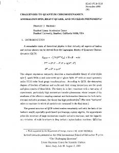
The main challenge in fabricating a BNG is precise positioning of wires with a very small inter-wire spacing. In the method described here, this challenge is overcome by weaving wires onto templates that have wire insertion features that facilitate alignment. The key idea is that the wire positioning is done at a distance much larger than the actual wire spacing. Figure 2a shows schematics of such a structure. The front face of the template has V-grooves that run vertically with a spacing of twice the desired wire spacing. The top and the bottom surfaces have wire insertion features that are aligned with the grooves and positioned along a line at a steep angle. Although the grooves are spaced by 100 or 200 m, the slots are spaced by 1 mm, which is easy to resolve by eye. By positioning wires into the matching wire insertion features on the top and bottom surfaces we guarantee that the wires are inserted into grooves on the front face of the template. Thus, precise positioning of wires with spacings too small to resolve by eye is easily achieved without the use of a microscope. Another challenge in fabrication is electrical isolation of two interleaved wire sets. This task is achieved by using two templates. The key idea is that wires are weaved onto two separate templates at twice the desired wire spacing and then the two templates are mated face-to-face (Figure 2b). The groove structure ensures that the two wire sets are placed between each other in the same plane. Though the two wire sets are initially separated by the depth of the grooves, they are brought to the same plane as they are secured onto a plastic mount. Electrical separation of the two wire sets is attained by inserting thin insulating sheets between the wire sets when mating the templates. Teflon, Ultem 1000, and FR-4 printed circuit boards have been successfully used as insulating materials. Figure 2c is a picture of a template. The templates are created from aluminum using conventional machining such as milling and wire electric discharge machining (EDM). The templates are then anodized for a black finish to have higher contrast with the gold-coated tungsten wires. The anodizing also removes sharp edges from the templates so that the wires will not be cut on the edges during weaving. The template in
J Am Soc Mass Spectrom 2007, 18, 1901–1908
TEMPLATE-BASED BNGs
1903
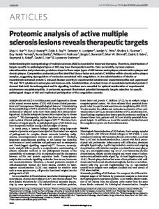
a 10 m diameter wire). The wire spool and the template are connected through a timing belt, so turning a handle rotates the template and unwinds the spool. As the template is rotated, the wire is placed into the wire insertion features on the template and wires are precisely positioned on the V-grooves. After the wires span the area of interest, both wire ends are fixed to the template using Scotch tape and the wires on the back of the template are detached and removed using a cutter. This process is repeated for a second template. When both templates are woven, thin insulating sheets are placed between the two templates and they are mated face-to-face. The mating may need to be done under a microscope to ensure that the grooves complement each other. After the weaving procedure, the templates are placed on top of a plastic mount, where the plastic mount fits into the square opening of the bottom template (a detailed drawing of the plastic mount is included in the Supplementary Material section as Figure S2). Although it is possible to use the mated templates as a BNG, it is preferable to transfer the wires
Figure 2. Template with wire insertion features. (a) Schematic of a template (not drawn to scale). The front face has V-grooves that are spaced by twice the desired wire spacing (2d), and on the top and bottom are wire insertion features that are positioned along a line at an angle. The distance between the insertion features are much larger than the distance between the V-grooves. (b) Schematic of two templates mating face-to-face. The groove structure ensures that the two wire sets are placed between each other. (c) Photos of a template that has V-grooves spaced by 200 m.
Figure 2c has V-grooves spaced by 200 m and the alignment features by 1 mm. The V-grooves are created using a 90 degree V-groove cutter and the wire insertion features using wire EDM. The wire EDM can cut out 150 m features using 100 m diameter wire at a reasonable price, but the price goes up for smaller sizes. To achieve 200 m spacing between the alignment features that are 150 m wide, the alignment features must be slightly bent at the opening for mechanical strength as shown in the magnified pictures in Figure 2c. A detailed mechanical drawing of the alignment features are shown in the Supplementary Material section Figure S1 (which can be found in the electronic version of this article). Figure 3a summarizes the overall weaving procedure, and Figure 3b presents a picture of the weaving device. When weaving wires onto a template, wire tension is maintained through a small weight (15 g for
Figure 3. BNG weaving procedure. (a) Schematic of the BNG weaving procedure. (b) A photograph of a BNG weaver. The weaver consists of a wire spool (A), template (B), a handle (C), a weight (D), a wire-guiding pulley (E), and a timing belt (F).
1904
YOON ET AL.
J Am Soc Mass Spectrom 2007, 18, 1901–1908
and then the wires must be inserted between the existing wires on the plastic under a microscope. The V-grooves on the template should be spaced by twice the desired wire spacing (2d). BNGs with wire spacings that are multiples (2d, 3d, 4d, etc.) of d can also be produced using the same template by skipping an appropriate number of V-grooves. BNGs with wire spacings that are half of d (d/2) can also be produced by mating two templates and following the procedures for a single template.
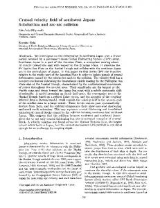
BNG Characterization Using the fabrication method described, four BNGs with wire spacings of 500, 200, 100, and 50 m have been fabricated using 10-m diameter gold-coated tungsten wires (California Fine Wires Inc., Grover Beach, CA). Two templates with V-grooves spaced by 200 m were used to make all four BNGs. The four BNGs were characterized physically and their static deflection performance was determined using ion beam images.
Physical Characteristics Figure 4. Photographs of four BNGs. (a) 100 m wire spacing BNG. A 10 m diameter gold-coated tungsten wire and plastic base made from are used. (b)–(e) The wires on the BNGs viewed through a microscope. The wire spacings of the fours BNGs are 500 (b), 200 (c), 100 (d), and 50 m (e).
to a plastic base. This is to ensure that the two wire sets lie in the same plane and also to re-use the templates repeatedly to fabricate more BNGs. However, the wire spacing precision can degrade while transferring the wires. The precision of the wire spacing can be maintained by using plastic bases with grooves at the desired wire spacing, where the wires in the template grooves are transferred to the grooves on the plastic. The distance between the top of the plastic mount and the wires is very small and this transfer can be achieved by pushing the wires down with thin metal plates. The wires are secured onto the plastic mount by screwing the metal plates and applying a vacuum-compatible conductive adhesive (CN2400 conductive epoxy, Chemtronics, Kennesaw, GA). The adhesive is left to dry for several hours. Then, the final BNG is released from the templates by cutting the wires between the plastic mount and the templates using a full-flush cutter. If only one template is available, the process can be done in two steps using the same template. In this procedure, wires are woven on the template and are transferred to the plastic base. After the conductive epoxy dries, the wires are cut to release the template and the process is repeated for the second wire set. In the second step, the wires are woven on the template
Figure 4 shows the four BNGs fabricated using the present method and Table 1 summarizes some of their physical characteristics. The standard deviation of the wire spacing was measured from the distances between the intensity maxima of the images of the BNG wires taken using a digital camera and a microscope. The active area is defined by the opening of the plastic base (15 mm ⫻ 15 mm) and the number of wires that span across the opening. The transmission in Table 1 is not an experimentally measured value and is calculated from the wire diameter and the wire spacing. The weaving time is the time taken to weave the wires and does not include the time for the conductive adhesive to dry. The capacitance of the BNGs was measured using an LCR meter (Passive Component LCR Meter 380193; Extech
Table 1. Characteristics of BNGs made using 10 m diameter gold-coated tungsten wires Wire spacing
500 m
200 m
100 m
50 m
Spacing std dev (% std dev) Active Area (mm ⫻ mm) Number of wires Transmission Weaving Timea Capacitance (Theoreticalb) Deflection coefficient kc
10 m (2%)
14 m (7%)
6.5 m (6.5%)
9 m (18%)
15 ⫻ 15 30 98% 15 min 10 pF (5 pF)
15 ⫻ 15 75 95% 30 min 23 pF (14 pF)
15 ⫻ 15 150 90% 1 hour 42 pF (35 pF)
15 ⫻ 12.5 250 80% 2 hours 80 pF (76 pF)
a
0.378
0.485
0.618
0.852
This is the weaving time, which does not include the time for the conductive epoxy to dry. Calculated using eq 1. c Calculated using eq 4. b
J Am Soc Mass Spectrom 2007, 18, 1901–1908
TEMPLATE-BASED BNGs
1905
Discussion Guideline for Wire Spacing Selection
Figure 5. Ion beam deflection as a function of deflection voltage. Static deflection images for a BNG with a wire spacing of 100 m. Twelve deflection voltages were used from 13 to 24 V.
Instruments, Waltham, MA) at 1 kHz. The theoretical capacitance is adapted from the equation for the capacitance of parallel wires [32] C⫽
N0L cosh⫺1(d ⁄ 2R)
A BNG is an ideal deflection plate capable of deflecting a beam of charged particles within a very thin volume. This property is derived from the positive and negative voltages applied to alternating wires, which cancels out the electric field. Thus, a BNG is well suited for applications that require rapid switching of charged particle beams, such as mass selection in TOFMS or ion beam modulation in HT-TOFMS. For many applications, a BNG with a wire spacing of 0.5 mm or larger is sufficient to achieve the time resolution in switching a beam of charged particles. Such large wire-spacing BNGs are easy to fabricate and many methods are available. Other applications demand more rapid
(1)
where N is the number of wires, 0 is the vacuum permissivity, L is the wire length, d is the wire spacing, and R is the wire radius. The deflection coefficient is calculated using the equation derived previously [1].
Beam Imaging To characterize the different deflection from the four BNGs, deflected ion beam was imaged using a multichannel plate (MCP) detector fitted with a P22 phosphor screen (Burle Electro-Optics Inc., Sturbridge, MA). Images were recorded using a standard CCD camera and frame grabber (PCI-1409; National Instruments, Austin, TX). Electrospray ionization (ESI) was used to deliver 2 mM tetrabutyl ammonium into the instrument. A spray voltage of 2.5 kV was used. The ion source consists of a heated capillary operated at 270 °C followed by an off-axis skimmer and a quadrupole ion guide driven at 2.94 MHz and 150 V (peak-to-peak). After the ions are transferred to the vacuum region of the mass spectrometer, the ions are accelerated to 1.5 keV and then focused by an Einzel lens through the BNG onto the detector. The distance between the BNG and the MCP detector is 82 cm. Ion deflection experiments are done in a flight tube that is evacuated to 2.0 ⫻ 10⫺7 torr. The BNG was floated at the same voltage as the flight tube and the voltages applied to the wires were between ⫾13 V and ⫾24 V relative to the flight tube voltage. Some of the ion beam deflection images are shown in Figure 5 and 6a for various deflection voltages and wire spacings. More images are included in the Supplementary Material section as Figure S3 (which can be found in the electronic version of this article). The pixels on the images were converted to distance by calibrating against the dark count image and the known size of the MCP. The ion beam position was extracted by fitting a Gaussian function to the intensity profiles.
Figure 6. Ion beam deflection for BNGs with varying wire spacings. (a) Static deflection images for four BNGs with wire spacings of 500, 200, 100, and 50 m. The deflection voltage was 19 V. (b) A plot of deflection distance versus deflection voltage for the four BNGs. The error bars are taken from the size of the deflected ion beam.
1906
YOON ET AL.
J Am Soc Mass Spectrom 2007, 18, 1901–1908
switching and require the construction of BNGs with smaller wire spacings, which is the topic of this article. As a rule of thumb for determining the necessary wire spacing, the following equation can be used:
d⫽
⌬T 2
冑
2zeV0 M
(2)
where d is the BNG wire spacing, ⌬T is the required time resolution, z is the number of charges on the ion, e is the electron charge, V0 is the acceleration voltage of the charged particle, and M is the mass of the charged particle. The BNG electric field decays to nearly zero at a wire spacing distance d away from the plane of the BNG. Thus, a charged particle must travel at least twice the wire spacing (2d) during ⌬T. This is because if the BNG voltage is turned on when the charged particle is within the deflection region (2d), the particle experiences partial deflection and leads to blurring of deflection angle [1]. For an ion of mass 20 kDa and kinetic energy 1500 eV, the equation predicts a wire spacing of 100 m or less for a time resolution of 50 ns (modulation at 20 MHz). Thus, for a constant kinetic energy beam, as the time requirement becomes more stringent, smaller spacing BNGs are necessary. Smaller wirespacing BNGs have less temporal blurring of deflection from this phenomenon and also have the advantage that smaller voltage is required to achieve the same deflection.
Physical Characteristics of BNGs As shown in Figure 4, the fabricated BNGs have regularly spaced wires on a plastic base that were transferred from the templates with alignment features. Both Ultem 1000 and Delrin have been used as the material for the plastic base and are compatible with high vacuum. The wires are secured on the plastic base using metal plates and conductive epoxy. The conductive epoxy takes several hours to set so the BNGs should be left to dry in air for at least one day before putting into vacuum. As shown in Table 1, the precision of the wire spacing is about 10 m. This limit in precision mainly results from the radius of curvature of the troughs of the V-grooves and the displacement of the wires during transfer from the templates to the plastic. Effects of the wire spacing precision on the performance of the BNGs will be discussed in the subsequent section. The capacitance of the BNGs was measured to be below 100 pF. The main contributions to the increased capacitance for smaller spacing BNGs are the reduced spacing and the increased number of wires. The RC time constant contribution from the capacitance of the BNGs is small such that the rise time of the voltage pulses is not affected. However, the transient current during the voltage switching can be substantial, and higher power requirement and better heat dissipation is
necessary for faster modulation rates and smaller wire dV spacing BNGs. Using I ⫽ C , the transient current for dt a 20 V voltage pulse with a 3 ns rising edge is calculated to be 67 mA for 10 pF and 0.67 A for 100 pF. The power requirement also goes up with the modulation rate because of the increased number of rising and falling edges. It is necessary to place a snubber circuit close to the modulation electronics to relieve the stress that the switching circuit must endure.
Performance of BNGs To test the performance of the BNGs fabricated using the template-based method, static ion beam deflection images were recorded as described previously. Figure 5 shows an ion beam deflected into two branches by a 100 m wire spacing BNG at deflection voltages Vp from 13 V to 24 V. Figure 6a is a comparison of images at Vp of 19 V using four BNGs with wire spacings of 500, 200, 100, and 50 m. The deflection angle increases with larger voltage and smaller wire spacing. More ion beam deflection images are found in Supplementary Material section Figure S3. An expression for the deflection angle has been derived previously [1]. If the deflection voltage is turned on and then off when an ion beam is at positions x0 and x1 relative to the plane of the BNG, the tangent of the deflection angle is given by tan␣(x0, x1) ⫽ k
冋
Vp 2 V0
2 ⫺ arctan(x0 ⁄ deff)
arctan(x1 ⁄ deff)
册
(3)
where k is a deflection constant, Vp is the deflection voltage (⫹Vp on one wire set and ⫺Vp on the other), V0 is the acceleration voltage of the ions, and deff is the effective wire spacing. The deflection constant k and effective wire spacing deff are functions of the wire spacing d and the wire radius R, and are given by k⫽
2ln[cot(R ⁄ 2d)]
deff ⫽ d cos((d ⫺ 2R) ⁄ 4d)
(4) (5)
For the imaging experiments, the deflection voltage was fixed and the maximum deflection is achieved according to the following equation. tan␣max ⫽ k
Vp V0
(6)
Figure 6b shows the distance between the two deflected ion beam branches at several deflection voltages for the four BNGs. The markers are the experimentally
J Am Soc Mass Spectrom 2007, 18, 1901–1908
TEMPLATE-BASED BNGs
measured distances and the solid lines are the theoretical values calculated using eq 6. For the 50 m wire spacing BNG, the ion beam is partially deflected out of the MCP detector above 19 V, and quantitative measurement of deflection distance was not possible. As predicted by eq 4 and 6, the deflection is linear in Vp and inversely logarithmic in d. The ion beam size after deflection was used for the experimental error bar. The error bar is much larger for the 50 m wire spacing BNG because the wire spacing is very small and the deflection angle is more sensitive to the variations of wire spacing. This blurring in deflection angle for 50 m spacing BNGs should not be confused with the temporal blurring for larger wire-spacing BNGs. The residence time res is the time required for an ion to pass through the deflection region of the BNG, where there is electric field. Because the electric field decays exponentially from the plane of the BNG and is almost zero at a distance of one wire spacing (d) away from the plane of the BNG, the deflection region is twice the wire spacing (2d) long. Thus, the residence time is defined as
res ⫽
2d v0
⫽ 2d
冑
M 2zeV0
(7)
where d is the wire spacing, v0 is the speed of the ion, M is the mass, e is the electron charge, and V0 is the acceleration voltage of the ion. The residence time res has to be smaller than the modulation pulse time width ⌬Tmod (100 ns for 10 MHz modulation). If the voltage on the BNG switches while an ion is travelling in the deflection region of the BNG, the ion will experience only partial deflection. This causes temporal blurring of the ion beam deflection at the detector. If res is longer than twice ⌬Tmod, then BNG will be switched on and off several times during the ion travel in the deflection region and the modulation information will be lost. Thus, res determines the time resolution of the BNG. As a demonstration of ion beam modulation, a 100 m wire spacing BNG was used for HT-TOFMS [14 – 16]. A continuous ion beam was modulated at 10 MHz using a Hadamard sequence and deconvoluted as shown in Supplementary Materials Figure S4. Electrospray ion beam images and counts measured while modulating the BNG also are shown in Supplementary Materials Figures S5 and S6. Figure 7 compares the advantages and disadvantages of small-spacing BNGs. As the wire spacing is reduced from 500 m to 50 m, the deflection constant k is increased from 0.38 to 0.85 and the residence time is reduced from 186 ns to 19 ns for an ion of mass 10,000 Da and kinetic energy 1500 eV. This means smaller voltages can be applied on the BNG and the maximum modulation rate can be 50 MHz for mass of 10,000 Da. The transmission, however, is decreased from 98 to 80% as the wire spacing is reduced from 500 m to 50 m for BNGs that use 10 m diameter wires. For wire spacing precision of 10 m, the deflection is not sensitive to wire
1907
Figure 7. Plot of performance figures of merit versus wire spacing. The plot shows the deflection constant k calculated using eq 4 (solid line), transmission T (dashed line,), and the residence time res calculated using eq 7 (dotted line). All calculations assume a wire diameter of 10 m. For the deflection constant k, the error bar is calculated from the deflection constant at wire spacing d ⫾ 10 m. The residence time is for an ion of mass 10,000 Da and kinetic energy 1500 eV.
spacing variations for wire spacings larger than 75 m. For smaller wire spacings, however, the deflection becomes increasingly sensitive to variations in wire spacing, which can lead to blurring in deflection angle. For wire spacing of 50 ⫾ 10 m, the deflection constant k has a relative standard deviation of 11%. If the wire spacing precision can be improved to 5 m, the deflection angle will be better defined at 50 m. As an extension to this work, the templates could be microfabricated by etching silicon wafers using photolithography and deep reactive ion etching (DRIE) or anisotropic HF etching. Two sets of grooves at a spacing of twice the desired wire spacing (2d) should be microfabricated on front and back surfaces of the wafer displaced by d from each other. Wire insertion features could be patterned on the grooves. Because one template has both sets of grooves, only one template is necessary. Thicker wafers should be used because the grooves need enough depth for the wires. Microfabricated templates could have smaller groove spacing (such as 20 m wire spacing), but the diameter of the weaving wires also have to be smaller and such wires are not strong enough to be manually handled. Thus, the main benefit of microfabricated templates would be to increase the precision of wire placement. To summarize, we have developed a simple method to fabricate BNGs with wire spacings as small as 50 m with minimal use of a microscope. This method relies on the use of two templates with alignment features that facilitate the precise positioning of wires. BNGs with wire spacings of 100 or 50 m can be woven in one or two hours. Using this method four BNGs were fabricated and characterized using an imaging detector and the experimental deflection measurements are in good agreement with theoretical predictions. Although small wire spacing BNGs are more difficult to fabri-
1908
YOON ET AL.
cate, they have the advantages of better time resolution and smaller deflection voltage requirement. This method provides a simple method to fabricate such BNGs with the main applications in time-of-flight mass spectrometry.
Acknowledgments This work was supported by the United States Air Force Office of Scientific Research (AFOSR grant FA9550-04-1-0076). OKY thanks the American Chemical Society, Division of Analytical Chemistry Fellowship, sponsored by Society for Analytical Chemists of Pittsburgh.
References 1. Yoon, O. K.; Zuleta, I. A.; Kimmel, J. R.; Robbins, M. D.; Zare, R. N. Duty Cycle and Modulation Efficiency of Two-Channel Hadamard Transform Time-of-Flight Mass Spectrometry. J. Am. Soc. Mass Spectrom. 2005, 16, 1888 –1901. 2. Loeb, L. B. Basic Processes of Gaseous Electronics; University of California Berkeley, Berkeley, CA, 1961. 3. Cravath, A. M. The Rate of Formation of Negative Ions by Electron Attachment. Phys. Rev. 1929, 33, 605– 613. 4. Bradbury, N. E.; Nielsen, R. A. Absolute Values of the Electron Mobility in Hydrogen. Phys. Rev. 1936, 49, 388 –393. 5. Weinkauf, R.; Walter, K.; Weickhart, C.; Boesl, U.; Schlag, E. W. Laser Tandem Mass Spectrometry in a Time of Flight Instrument. Naturforsch Teil A 1989, 44, 1219 –1225. 6. Beussman, D. J.; Vlasak, P. R.; McLane, R. D.; Seeterlin, M. A.; Enke, C. G. Tandem Reflectron Time-of-Flight Mass Spectrometer Utilizing Photodissociation. Anal. Chem. 1995, 67, 3952–3957. 7. Vlasak, P. R.; Beussman, D. J.; Davenport, M. R.; Enke, C. G. An Interleaved Comb Ion Deflection Gate for m/z Selection in Time-ofFlight Mass Spectrometry. Rev. Sci. Instrum. 1996, 67, 68 –72. 8. Fernandez, F. M.; Smith, L. L.; Kuppannan, K.; Yang, X.; Wysocki, V. H. Peptide Sequencing Using a Patchwork Approach and Surface-Induced Dissociation in Sector-TOF and Dual Quadrupole Mass Spectrometers. J. Am. Soc. Mass Spectrom. 2003, 14, 1387–1401. 9. Li, J.; Taraszka, J. A.; Counterman, A. E.; Clemmer, D. E. Influence of Solvent Composition and Capillary Temperature on the Conformations of Electrosprayed Ions: Unfolding of Compact Ubiquitin Conformers from Pseudo-Native and Denatured Solutions. Int. J. Mass Spectrom. 1999, 187, 37– 47. 10. Baumbach, J. I.; Pilzecker, P.; Trindade, E. Monitoring of Circuit Breakers using Ion Mobility Spectrometry to Detect SF6-Decomposition. Int. J. Ion Mobility Spectrom. 1999, 2, 35–39. 11. Jarvis, G. K.; Peverall, P.; Mayhew, C. A. A Novel Use of an Ion-Mobility Mass Spectrometer for the Investigation of Electron Attachment to Molecules. J. Phys. Chem. B 1996, 29, L713–L718.
J Am Soc Mass Spectrom 2007, 18, 1901–1908
12. Ashbury, G. R.; Hill, H. H. Negative Ion Electrospray Ionization Ion Mobility Spectrometry. Int. J. Ion Mobility Spectrom. 1999, 2, 1– 8. 13. Clowers, B. H.; Hill, H. H. Mass Analysis of Mobility-Selected Ion Populations Using Dual Gate, Ion Mobility, Quadrupole Ion Trap Mass Spectrometry. Anal. Chem. 2005, 77, 5877–5885. 14. Brock, A.; Rodriguez, N.; Zare, R. N. Characterization of a Hadamard Transform Time-of-Flight Mass spectrometer. Rev. Sci. Instrum. 2000, 71, 1306 –1318. 15. Zare, R. N.; Fernandez, F. M.; Kimmel, J. R. Hadamard Transform Time-of-Flight Mass Spectrometry: More Signal, More of the Time. Angew. Chem. Int. Ed. 2003, 42, 30 –35. 16. Trapp, O.; Kimmel, J. R.; Yoon, O. K.; Zuleta, I. A.; Zare, R. N. Continuous Two-Channel Time-of-Flight Mass Spectrometric Detection of Electrosprayed Ions. Angew. Chem. Int. Ed. 2004, 43, 6541– 6544. 17. Kwasnik, M.; Zuleta, I. A.; Fuhrer, K.; Gonin, M.; Zare, R. N.; Fernandez, F. M. Monolithic Atmospheric Pressure Micro-Electrospray Ion Mobility Spectrometer. Proceedings of the 53rd ASMS Conference on Mass Spectrometry; San Antonio, TX, June, 2005; Poster TP194. 18. Clowers, B. H.; Siems, W. F.; Hill, H. H.; Massick, S. M. Hadamard Transform Ion Mobility Spectrometry. Anal. Chem. 2006, 78, 44 –51. 19. Szumlas, A. W.; Ray, S. J.; Hieftje, G. M. Hadamard Transform Ion Mobility Spectrometry. Anal. Chem. 2006, 78, 4474 – 4481. 20. Nowak, D. J., Rice, J. E., Bianco, D. R. Ion Gating Grid. U.S. Patent 4,150,319, April 17, 1979. 21. Szumlas, A. W.; Rogers, D. A.; Hieftje, G. M. Design and Construction of a Mechanically Simple, Inter-Digitized Wire Ion Gate. Rev. Sci. Instrum. 2005, 76: 086108. 22. Stoermer, C. W.; Gilb, S.; Friedrich, J.; Schooss, D.; Kappes, M. M. A High Resolution Dual Mass Gate for Ion Separation in Laser Desorption/Ionization Time of Flight Mass Spectrometry. Rev. Sci. Instrum. 1998, 69, 1661–1664. 23. Karl, M., Burgartz, R. Method of Manufacturing a Gating Grid. U.S. Patent 5,465,480, November 14, 1995. 24. LeCursi, N.; LeGore, L. J.; Jackson, R. H.; Crothers, C. B. H.; Kleban, P. H.; Frederick, B. G. Fabrication of Chopper for Particle Beam Instrument. U.S. Patent 6,781,120, October 24, 2004. 25. Brock, A.; Rodriguez, N.; Zare, R. N. Hadamard Transform Time-ofFlight Mass Spectrometry. Anal. Chem. 1998, 70, 3735–3741. 26. Rodriguez, N. Hadamard Transform Time-of-Flight Mass Spectrometry: Implementation and Characteristics. Ph.D. Thesis, Stanford University, Stanford, CA, September 1999. 27. Kimmel, J. R.; Engelke, F.; Zare, R. N. Novel Method for the Production of Finely Spaced Bradbury-Nielsen Gates. Rev. Sci. Instrum. 2001, 72, 4354 – 4357. 28. Charles, H. K., Francomacaro, A. S., Keeney, A. C., Lee, D. M., Cornish, T. J. Gating Grid and Method of Making Same. U.S. Patent 6,977,381, December 20, 2005. 29. Zuleta, I. A., Zare, R. N. Microfabricated Beam Modulation Device. US Patent 7,176,452, February 13, 2007. 30. Verbeck, G. F.; Saini, R.; Wylde, J.; Tsui, K., Ellis, M. MEMS Assembled Mass Spectrometry: A Novel Approach to Miniaturization and Construction of Electron and Ion Optics. Proceedings of the 54th ASMS Conference on Mass Spectrometry; Seattle, WA, May 28 –June 1, 2006. 31. Yoon, O. K., Zare, R. N. U.S. Patent Pending. 32. Rao, N. N. Elements of Engineering Electromagnetics; Prentice Hall: Englewood Cliffs, NJ, 1977; p 422.