ing planetary archives, field test sites, and synthetic and analytic ... Assembling a terrain site model ..... SIMSCAPE's Python interface is very useful for creating.
SECOND INTERNATIONAL CONFERENCE ON SPACE MISSION CHALLENGES FOR INFORMATION TECHNOLOGY (SMC-IT 2006)
1
S IM S CAPE Terrain Modeling Toolkit Abhinandan Jain, Jonathan Cameron, Christopher Lim, John Guineau Jet Propulsion Laboratory California Institute of Technology 4800 Oak Grove Drive, Pasadena, CA 91109
Abstract— Planetary space mission applications involving landers and surface exploration vehicles make extensive use of terrain models within their simulation testbeds. Such terrain models are large, complex and have a variety of attributes including topography, reflectivity, soil mechanics, and hazard information. Sources for the terrain models include planetary data archives, field tests, and analytically constructed models. Simulation uses of such models include surface rover vehicles’ kinematics and dynamics models, instrument models, camera models and robotic arm models. This paper describes the S IM S CAPE middleware toolkit for providing a common infrastructure to represent terrain model data from multiple data sources and make them available to simulation applications. S IM S CAPE simplifies the overall simulation design by eliminating the traditional need for custom terrain model interfaces to terrain data sources for simulation users. S IM S CAPE provides a collection of libraries and tools to use and manage terrain environment models within the simulation applications.
I. I NTRODUCTION Many types of planetary exploration missions require simulations that involve software models of the terrain surface of planetary bodies. Missions that involve rovers operating on the planet’s surface require terrain models with rover simulations to develop flight software and test mission operations plans. Space missions that land a payload on a planet’s surface also require terrain models for realistic radar models for developing on-board landing control software. Surface rover simulations require rich, complex terrain models involving a wide range of surface attributes including topography, surface imagery, soil mechanics properties, hazard conditions, and optical characteristics such as reflectivity. First, the terrain model must represent basic surface topography to compute the location of the ground under each rover wheel. At the same time, the soil mechanics properties are needed to compute the forces acting on the rover wheels for wheel slippage and sinkage models. These computations are carried out for each wheel several times for each simulation step. Fast algorithms that work with the terrain models are needed for such demanding applications. Planetary exploration rovers use imagery from on-board cameras to plan motions. Creating simulated images for on-board cameras also requires terrain models with appropriate surface optical properties such as imagery and reflectance. Landing a mission on a planetary surface is a risky and difficult process. Extensive planning and simulation is necessary to develop landing control software and to reduce the risks during landing. Terrain models needed for landing simulations involve basic topography as well as other types of
specialized terrain information. For instance, laser altimeters may need topography and surface reflectivity. Radar models also need specialized properties such as ground density to estimate the strength of radar returns. Recent landing missions often include landing approach control based on on-board camera imagery. Construction of suitable images leads to requirements for surface optical properties similar to those for rover camera operations. Science teams also need high-quality terrain models for simulating science instruments and planning surface operations. These simulation applications need to incorporate raw terrain data from a variety of sources including planetary data archives, field tests, synthetic models (derived from existing terrain models) as well as algorithmically generated ones. Such primary terrain data needs to be processed and assembled into a terrain model prior to use by applications. This often requires piecing together data from different sources, processing relative spatial transforms among them, assigning attributes to the geometry, handling different data formats and representations and using height field and/or 3D models as appropriate The S IM S CAPE terrain modeling toolkit described here arose out of the recognition that while the different terrain applications represent a wide diversity in terrain modeling and algorithm requirements, there is also a significant overlap in the requirements among them. Our goal was to create a common toolkit that could be used and shared by a wide range of simulation applications. A high level description of the requirements for S IM S CAPE are: • Support multiple representations of the terrain geometry. These include 2.5D digital elevation map grid representations, point cloud representations, 3D mesh representations, and 2.5D triangulated irregular network (TIN) mesh representations and support for geo-referenced planetary data models. • Support algorithms and methods for transformations between different terrain model representations. • Support use within applications as a general-purpose, embeddable library library with efficient algorithms and methods for operating on terrain models. • Support terrain model data from different sources including planetary archives, field test sites, and synthetic and analytic terrain models (Figure 1). • Support exporting and importing terrain models to and from a variety of standard terrain data formats including PDS, GeoTiff, USGS ISIS and VRML. • Support the use of overlays of surface properties such as material composition, texture, albedo, terra-mechanics parameters, reflectivity, and user defined properties onto
SECOND INTERNATIONAL CONFERENCE ON SPACE MISSION CHALLENGES FOR INFORMATION TECHNOLOGY (SMC-IT 2006)
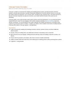
Fig. 1. S IM S CAPE as middleware for terrain models within simulation applications
•
the underlying terrain geometry. Support for composite terrain models assembled from heterogeneous component terrain models, eg., base terrains together with component 3D rock models (Figure 2). This includes the ability to assemble terrain models from a variety of topographic components in a tree hierarchy with relative transforms to rotate, position and scale the subcomponents.
2
[6] provides software for processing data fro orbiters and instruments. There are also many Geographic Information Systems products available, such as GRASS [7], that provide useful tools for geographic data analysis. This paper describes the S IM S CAPE middleware toolkit that has been developed to meet the simulation requirements described above. S IM S CAPE provides a common infrastructure for importing terrain model data from multiple data sources and making them available to simulation applications. These terrain data sources include planetary and empirical terrain data sets, terrain synthesis models and analytical models. The S IM S CAPE infrastructure simplifies the overall simulation design by eliminating the traditional need for custom terrain model interfaces to terrain data sources and simulation users. S IM S CAPE provides a collection of libraries and tools to use and manage terrain models within spacecraft simulation applications. As described in more detail below, S IM S CAPE uses some of available open-source tools and libraries described above to develop an integrated terrain modeling capability for use by simulation applications. Section II provides an overview of the S IM S CAPE design architecture, object types and their functionality. Section III describes algorithms and methods for manipulating the S IM S CAPE objects as well as for transforming them into one another. Section IV describes the various data formats supported for importing and exporting terrain data. Section V describes support for storing and retrieving terrain models to and from the file system. Section VI describes user interfaces for visualizing terrain models and Section VII describes simulation applications using S IM S CAPE. II. S IM S CAPE O BJECT H IERARCHY
Fig. 2.
Assembling a terrain site model
Support persistent storage and retrieval of assembled terrain models for later retrieval and use by applications. • Provide an open architecture to allow extension of the library with new algorithms and terrain model types by users. There are many products that provide some of these required capabilities. But none cover all of the needs of terrain modeling for planetary space missions. Daylon Graphics offers a stand-alone product called Leveller [2] that provides an ability to construct and edit 3D terrains. The GNU Triangulated Surface Library (GTS) [1] has many useful functions for modeling surfaces with sets of triangular faces, but does not deal with gridded elevation data. The Geospatial Data Abstraction Library (GDAL) [4] supports importing of raster terrain data from a wide range of data formats. The Planetary Data System (PDS) [5] provides planetary images and data collected by various NASA missions and related software. The Integrated Software from Images and Spectrometers (ISIS) •
As shown in Figure 3, S IM S CAPE provides a class hierarchy that supports various terrain modeling needs. Broadly, these classes fall into the following categories: • Classes to represent the topographic geometry of terrain. • Classes to overlay surface properties onto the terrain geometry. • Container classes to assemble component terrain models into hierarchical models. • Classes to store and retrieve terrain models from the file system. Before examining classes in each of these categories, we will briefly discuss the base class from which they are derived. All storable S IM S CAPE classes are derived from the C ORE O BJECT class. Each class derived from C ORE O BJECT implements methods to save and restore their object-specific data from the persistent store. For more details on persistent stores see Section V. The base class C ORE O BJECT also provides functions to assign and retrieve meta-data about the object, referred to by S IM S CAPE as “attributes”. There are two types of attributes. The first type of attributes are user-defined attributes. Their purpose is to provide a way for users to store and retrieve textual data about an object such as labels, annotations, data sources, etc. C ORE O BJECT provides the capability to save and retrieve arbitrary text strings with keys. A second type of
SECOND INTERNATIONAL CONFERENCE ON SPACE MISSION CHALLENGES FOR INFORMATION TECHNOLOGY (SMC-IT 2006)
Fig. 3.
The S IM S CAPE class hierarchy
attribute provides simple access to known data internal to each topographic object. For instance, the number of samples for a T OPO D EM can be accessed via a read-only attribute with the key ’samples’. Other known attributes such as the textual description of the T OPO D EM (that has the key ’description’) can be accessed or modified via the attribute get/set functions. These two types of attributes use the same underlying mechanisms to store their information in the persistent store so that objects retrieved from the persistent store will include all of their attribute data. We begin by examining the primary topographic object classes. A. Primary topographic object classes 1) TopoDem: One of the primary topographic classes is the T OPO D EM. As the name implies, this is primarily a DEM (Digital Elevation Map). The elevation values are laid out in a regular x-y rectangular grid. For each x-y value pair, there is only one elevation (Z) value. The T OPO D EM provides data access and interpolation functions to compute the elevation value for a specified x-y location. Each T OPO D EM contains information about the extent (physical area) that the data grid covers. DEM topographic data contain grids of regularly spaced elevation data. In some cases, each elevation data point represents an average elevation in the grid square (or rectangle) that contains the point. This type of data is called CENTERPIXEL. In other cases, the elevation data denotes elevation at one of the corners of the grid square. This type of data is called FENCEPOST. T OPO D EM supports both types of elevation data representations. T OPO D EMs can be created from elevation data stored in files (or persistent stores, explained in more detail in Section V). The second source of data for T OPO D EMs is via an analytic construction capability. T OPO D EMs can be created with a number of ideal geometric surfaces such as flat surfaces, sloped surfaces, wavy surfaces (sine/cosine wave function), and other similar shapes. Users can also define new analytic surfaces. T OPO D EMs also provide many functions that provide useful data beyond simple elevation lookup. These include
3
functions to compute the normal to the surface at a specified location, compute statistics for a small patch surrounding a specified location, and other functions geared towards ground vehicle simulations. Although the most common use of the T OPO D EM class is to provide access to a regular, Cartesian grid of elevation data, the coordinate types can be more general. For instance, T OPO D EM coordinates can represent radius and angle coordinates for a polar grid. Similarly, T OPO D EM coordinates can also be latitude and longitude pairs in the T OPO P LANET class (see Section II-A.5 for more details about T OPO P LANETs). T OPO D EM is based on a C++ template and can contain elevation data in double, float, or even integer types. 2) TopoCloud: A T OPO C LOUD is simply a collection of xy-z points called vertices. T OPO C LOUDs support adding new vertices, merging T OPO C LOUDs, and other related functions. A cloud of points may be the 3D range data obtained from stereoscopic image correlation. 3) TopoMesh: A key limitation of the T OPO D EM is that it is 2.5 dimensional (meaning that there is only one elevation data value for each x-y location). For some vehicle simulations, a truly 3D surface class is necessary to model terrain surfaces with realistic 3D characteristics such as overhangs. The T OPO M ESH class provides full 3-dimensional irregular mesh capability. The surface is broken up into a set of ”Faces” (which are usually triangles) and the vertices necessary to define each face. The T OPO M ESH class derives from the T OPO C LOUD class (which provides basic vertex storage and operations). The T OPO M ESH type provides functions to access/add/delete faces, merge T OPO M ESHs, and refine (subdivide) existing faces to reduce the size of all faces below a desired threshold. 4) TopoTinMesh: For 2.5D terrain data, the T OPO M ESH class provides the advantage of being economical in the number of polygons needed to represent the surface, while the T OPO D EM class provides fast look up of elevation values. The T OPOT IN M ESH class combines these advantages for 2.5D terrain models. A T OPOT IN M ESH is an irregular mesh with faces and vertices that is constrained to be 2.5D by the vertex/face construction process. This means that a T OPOT IN M ESH provides the unambiguous elevation lookup of a T OPO D EM with the data flexibility of a T OPO M ESH. A well-constructed T OPOT IN M ESH represents the same elevation data as a T OPO D EM with considerably reduced fewer polygons and reduced storage requirements with minor runtime elevation lookup penalties. 5) TopoPlanet: The T OPO P LANET class is the primary end-user class for dealing with the surface of a planet. A T OPO P LANET represents the surface of a planet in a generalized way by adding an offset to an nominal planetary radius value based on some idealized reference surface model (such as a sphere or an ellipsoid). To accomplish this, T OPO P LANET uses the P LANET M ODEL class to compute radius values from a latitude and longitude pair or convert from latitude and longitude pairs to x,y,z Cartesian locations (and vice versa). The reference surface accounts for the fact that planets are not in perfectly spherical in general, but are usually elliptical
SECOND INTERNATIONAL CONFERENCE ON SPACE MISSION CHALLENGES FOR INFORMATION TECHNOLOGY (SMC-IT 2006)
or oblate in shape, with flattening at the poles relative to the equator. Using a fixed reference surface also allows the software to make use of the limited precision of floating point number formats for describing the surface detail by factoring out a large constant reference value associated with planetary radii. P LANET M ODEL is a generalized base class. It contains an object of the P LANET S URFACE R EFERENCE class that is the base class for planetary reference surfaces and knows how to compute a reference surface radius for any specified (planetocentric) latitude and longitude pair. S IM S CAPE provides two simple derived classes, E LLIPSOID and S PHERE, that model a spherical and ellipsoidal reference surface, respectively. There are two classes derived from P LANET M ODEL: P LANET D ETIC and P LANET C ENTRIC. These two classes do the primary work of adding offsets to the reference surface radius. P LANET C ENTRIC assumes the offset is added to the reference surface in a direction radially outward from the center of the planet. P LANET D ETIC assumes the offset is added in a direction normal to the local reference surface at the specified location. The P LANET M ODEL class also uses the class P LANET C OORD I NFO (and several related classes) to take care of whether longitudes increase in the eastward or westward directions, and how to deal with longitude wrapping. To provide the offset elevation data at any specified latitude and longitude, the T OPO P LANET class uses an embedded T OPO D EM object. For this usage, the typical meaning of x and y of the T OPO D EM are replaced by longitude and latitude (respectively) and the elevation values of the T OPO D EM are interpreted as offsets from the reference surface. When a T OPO P LANET object is created, the user must first create an appropriate P LANET M ODEL object (using the P LANET D ETIC class or a P LANET C ENTRIC class) with the appropriate reference surface (such as E LLIPSOID). The resulting P LANET M ODEL object is used to create the T OPO P LANET object and is installed as a data member of the T OPO P LANET object for future surface location computations. The T OPO P LANET class provides various useful functions such as the ability to compute the radius or elevation offset of the surface at a specified latitude and longitude, compute local surface normals, and compute the intersection of a ray with the surface. The design of the T OPO P LANET class and the classes that it uses provides a flexible and extensible way to implement complex planetary topographic systems.
Fig. 4. Mars Gusev site terrain mesh with detail DEM and 3D rock meshes
an affine transform (which contains a position offset, scale, and a rotation matrix). The position/rotation offset applies to the node, all its children, and to the contained topographic object. This provides the ability to position all topographic objects as needed. C. Surface Property Overlays Elevation data is essential to vehicle simulations but is not the only type of data needed to describe an area of terrain. Important science and engineering data related to terrains are available and must be associated with terrains so that the data can be accessed for locations within the terrain. Examples include images to be overlaid on the surface for visualization purposes, soil properties at specific locations (eg. soil types, cohesion), and spectral properties of the terrain surface. These 2D raster data sets are called surface property ”overlays” in S IM S CAPE and are derived from the S URFACE P ROPERTY base class. Multiple surface property overlays may be associated with a T OPO object. S IM S CAPE allows overlaid surface properties to be specified in frames different from that of the parent T OPO object. In order to access a surface property value at a T OPO vertex, the overlay data set must be “bound” to the vertices on the parent T OPO object. The “binding” process (see Figure 5) registers the overlay (including a position/rotation offset) with the parent topographic object and initializes various internal data structures for accessing the overlay data. Each overlay
B. Container Types - Trees and Nodes In order to support the assembly of topographic models from various sources the S IM S CAPE framework provides a T OPOT REE tree class populated with T OPOT REE N ODE objects. The topology of the tree structure is a simple downward branching tree. Each T OPOT REE N ODE object can contain a set of T OPOT REE N ODE children. Each T OPOT REE N ODE contains a single topographic data object such as a T OPO D EM or a T OPO M ESH. The relative position and rotation of the node (with respect to its parent node) can be specified using
4
Fig. 5.
Binding of surface attributes to the T OPO surface objects
SECOND INTERNATIONAL CONFERENCE ON SPACE MISSION CHALLENGES FOR INFORMATION TECHNOLOGY (SMC-IT 2006)
provides its own accessor functions that return S URFACE P ROPERTY values for specific locations (x-y or x-y-z depending on the type of topographic object). For instance, an image to be overlaid over a topographic object is called a T EXTURE OVERLAY. The T EXTURE OVERLAY class is derived from S URFACE P ROPERTY and provides a primitive data type called T EXTURE C OORDINATE (containing an s,t image coordinate pair). When the bound T EXTURE OVERLAY information is needed, it can be accessed from the parent topographic object and T EXTURE C OORDINATEs can be generated for specified x-y coordinates. In the process of binding surface properties on to topographic objects, a coordinate map can be specified. If the topographic object is essentially 2.5 dimensional (for T OPO D EMs, for instance), a simple one-to-one correspondence between the surface property set and the underlying topographic object might be appropriate. However, if the topographic object is 3 dimensional (like a T OPO M ESH), controlling how to map the surface property to the 3D object may not be as simple. Several coordinate mapping classes are provided for this purpose (and the user can create new mapping classes derived from one of the existing ones). For instance, the class C OORDA FFINE M AP 2D can introduce an arbitrary affine transform (offset, rotation, and skew) in the mapping process. See the left part of Figure 6 for an example including skew. The user can also define a custom mapping using the C OORD C USTOM M AP 2D class as shown in the right part of Figure 6.
Fig. 6.
Fig. 7.
5
Left: 3D Coordinate Mappings For Binding of Surface Properties
the new classes can be easily loaded at run time so that the new functionality is available without recompiling the base S IM S CAPE library. Each new class also provides basic functions to save its data to a persistent store so that its classes can be saved and restored from the persistent store like any of the basic classes of S IM S CAPE. The new userdefined classes can be extensions of existing classes or be created to perform a single function such import data from external formats (“Importers”), export data to external formats (“Exporters”), convert an object from one type to another (“Transformers”), or modify an object without changing its type (“Manipulators”). See Figure 2. More details about these types of objects will be covered in Section III and following.
2D Coordinate Mappings For Binding of Surface Properties
Interesting and useful mappings for 3-dimensional figures are also available, including a 2D mapping, a spherical mapping using C OORD S PHERICAL M AP 3D (see left image in Figure 7) and a user defined custom mapping using C OORD C USTOM M AP 3D (see the right image in Figure 7 and note that the same texture is mapped to each face of the cube). Although these example surface property mappings are shown for textures (images), the same capability can be used to map other types of surface properties onto topographic objects. It is also possible to bind an overlay (along with relative position/rotation offsets) to T OPOT REE nodes. Such overlays are applied to the T OPOT REE N ODE sub-tree. D. Architecture Extensibility S IM S CAPE supports extensibility by the mechanism of runtime dynamic loading of extension libraries. The user can extend any of the base classes provided by S IM S CAPE and
Fig. 8.
Run-time loadable dynamic extensions
III. T RANSFORMERS AND M ANIPULATORS Many common operations on basic topographic objects involve some type of manipulation of the data in the topographic object and constructon of a new topographic object of the same type. These functions can be thought of as manipulators since the object returned is of the same type as the original, but the internals have been changed or manipulated. (In most cases, the original object has not been modified.) For instance: • The function T OPO D EM ::getPatch() allows the caller to specify a region or patch of a terrain T OPO D EM and return the patch as a T OPO D EM.
SECOND INTERNATIONAL CONFERENCE ON SPACE MISSION CHALLENGES FOR INFORMATION TECHNOLOGY (SMC-IT 2006)
6
In T OPO M ESH::refine(resolution), the T OPO M ESH adds vertices to the mesh as necessary to ensure that no vertex is farther away from another vertex than the specified resolution. The T OPO M ESH is updated in place. • In T OPOT REE ::normalize(), the T OPOT REE is traversed and a new T OPOT REE is constructed for which all transforms are applied to the internal data of the topographic objects (such as vertex data) so that all the transformations become identity transformations and the original transforms are no longer necessary. The normalized tree is more efficient at run-time because the transforms are not needed. In addition, there is a need at times to transform a terrain model from one type into another. For instance, this can happen if the source data is of a specific type (eg. an irregular mesh) while the application has a need for a 2.5D grid terrain data type. At times, in more complex simulation scenarios, it is possible to use multiple different representations of the same terrain by different modules within the simulation. For instance a T OPOT REE representation with component 3D mesh models is very suitable for graphics visualization, while a 2.5D T OPO D EM version of the same tree may be needed for a wheel/soil dynamics model. Algorithms and methods that convert one model type into another are referred to as transformers. Examples of such transformers within S IM S CAPE include: • A transformer that converts a 3D T OPO M ESH into a 2.5D T OPO D EM model that takes as arguments a projection plane and a grid resolution for the desired T OPO D EM. The algorithm projects the irregular T OPO M ESH onto the plane and samples along the desired grid to create the T OPO D EM. This transformer makes use of the transformer from a T OPO M ESH to a T OPOT IN M ESH during the projection process. • A transformer to convert a normalized T OPOT REE into a T OPO D EM. This transformer essentially merges all the component T OPO objects within the T OPOT REE into a T OPO M ESH and then converts it into a T OPO D EM. We plan to add additional transformers such as those generating surface property overlays for properties such as roughness, slopes, height fields from a T OPO object.
for the creation of T OPO D EM terrain models from a variety of data formats. GDAL is an open source software library for raster geospatial data formats. As a library, it presents a single abstract data model to the calling application for all supported formats. The GDAL library has been used to develop an importer extension to allow importing of a large number of widely used data formats [8] into S IM S CAPE. This importer can also handle raster data from several image format files. • The Planetary Data System (PDS) [5] is a publicly available archive that distributes scientific data from NASA planetary missions, astronomical observations, and laboratory measurements. The data is available in the PDS format with header information describing the data sets. The PDS site also provides software for processing the PDS data and has been used to develop a T OPO P LANET importer for S IM S CAPE. • The Integrated Software for Imagers and Spectrometers (ISIS) [6] provides a tool for processing, analyzing, and displaying remotely sensed image data. ISIS primarily handles 2-D image data (as single-band cubes) and 3-D data (as multi-spectral or hyper-spectral cubes) from imagers and spectrometers. S IM S CAPE imports ISIS data by using the ISIS toolkit to export data into TIFF format followed by the use of the GDAL importer to complete the import. • S IM S CAPE also can import simple raster format data consisting of ASCII and binary height field data into a T OPO D EM object. • S IM S CAPE also can import range map data generated from stereo camera pairs into a T OPO C LOUD. Such data is typically obtained by camera sensors on surface exploration rovers. Exporting terrain models into external data files is supported in S IM S CAPE as follows: • S IM S CAPE uses the GDAL library for exporting T OPO D EM model data into external data formats. The export formats in the GDAL library supports are a subset of those supported for importing. All of these formats are available to S IM S CAPE via the GDAL library. • To facilitate 3D graphics visualization, S IM S CAPE supports the export of all T OPO object data into VRML files.
IV. E XPORTERS AND I MPORTERS
V. P ERSISTENT S TORE A persistent storage system allows S IM S CAPE objects (surfaces, rocks, textures, etc.) to be saved to a storage device for later retrieval. The persistent storage class (“Store”) in S IM S CAPE can be thought of as an “input/output stream”; objects can be read and written to the stream and the P ERSIS TENT S TORE class takes care of loading or storing the object’s binary data from/to storage. The P ERSISTENT S TORE class has an abstract device interface to support different types of storage. Currently S IM S CAPE uses an XML schema to save objects, but other storage types such as SQL databases and even flat files can be implemented in the future. The resulting P ERSISTENT S TORE storage files are portable and can be transported between different machines that support S IM S CAPE.
•
The import and export of terrain data for different formats is supported by specialized importer/exporter classes in S IM S CAPE. This mechanism allows the addition of support for new formats in the future. Most common data formats are for data in regular grid format that are suitable for creation of T OPO D EM and T OPO P LANET terrain models. Several providers also support the specification of geo-referencing data along with projection information for the data. These data providers also often provide libraries that support processing such data files. S IM S CAPE makes use of these libraries where available to allow importing of such terrain models. The key data import formats supported by S IM S CAPE include: • S IM S CAPE includes a Geospatial Data Abstraction Library (GDAL) [4] based terrain model data importer
SECOND INTERNATIONAL CONFERENCE ON SPACE MISSION CHALLENGES FOR INFORMATION TECHNOLOGY (SMC-IT 2006)
The P ERSISTENT S TORE is extensible and can support any C++ class type derived from C ORE O BJECT; new S IM S CAPE objects can be added without the need for recompiling the entire S IM S CAPE library. This is implemented by requiring each S IM S CAPE object to register methods to load and save itself to the P ERSISTENT S TORE. The list of loading and saving methods is keyed by the object’s class type. To load an object from the store, the P ERSISTENT S TORE searches the list of registered classes for the specified class type and invokes the necessary load methods to reconstruct the object. Since a S IM S CAPE object may be derived (subclassed) from another S IM S CAPE object, each S IM S CAPE object also saves its complete class hierarchy (type chain) to the store. When restoring an object from the store, the most specialized class available is used to create the object. Each S IM S CAPE object gives itself a unique ID string to distinguish itself from other S IM S CAPE objects of the same type. Methods for saving and reloading objects can be loaded and registered at run-time using the dynamic loading capability described earlier. Therefore users can create new classes that can be saved to persistent stores. When writing to the store, each S IM S CAPE object also saves a version number; when loading from the store the S IM S CAPE object can therefore detect whether the stored object was created with a newer or older version of S IM S CAPE and process it appropriately. As mentioned earlier, the P ERSISTENT S TORE currently stores objects into an XML file. The XML schema is implemented as follows: 1) Objects are saved in a tree structure in the XML file with each child object saved as a leaf (node) of its parent object’s node so reconstructing an object with child objects is simply a matter of walking the tree. 2) Arrays of simple data types (integers, strings and floating point numbers) are compressed and stored in separate files to save space. The path to the array file is stored in the XML file. 3) Large data files (eg., image files) are also stored in separate files with the paths kept in the XML file. VI. U SER I NTERFACE The S IM S CAPE toolkit includes a GUI for browsing and editing terrain models as well as a 3D visualization interface based on a JPL-developed 3D graphics toolkit called Dspace for visualizing the terrain models. While S IM S CAPE provides a portable and well-defined C++ interface, a Python [9] scripting interface is also available for all the object classes. The Python interface is auto-generated using the SWIG [10] wrapper generator tool. The S IM S CAPE Python classes closely mimic the underlying C++ classes. S IM S CAPE’s Python interface is very useful for creating scripts to implement functions needed to prepare and manipulate S IM S CAPE terrain models. Such scripts have been used to develop a regression test suite as well as a host of tutorial examples for using the S IM S CAPE objects. The Python scripting interface has also been used to develop a GUI browser for S IM S CAPE persistent stores (Figure 9).
Fig. 9.
7
The S IM S CAPE GUI browser
The browser allows a user to browse and edit the contents of one or more S IM S CAPE stores. The GUI also displays the defined attributes for the objects. Several of the manipulator and transformer methods available for the objects can be invoked from the GUI as well. The GUI also provides hooks to visualize a 3D graphics model of any of the T OPO objects. VII. A PPLICATIONS We briefly describe a few simulation applications that currently use S IM S CAPE for their terrain modeling needs. S IM S CAPE is in use by the ROAMS rover simulator [11], the DSENDS entry, descent and landing simulator [12] and instrument simulators. Beyond the terrain model definition, S IM S CAPE provides high-performance algorithms for embedded use by these simulations. • ROAMS (Rover Analysis, Modeling and Simulation) [11] is a physics-based simulation tool for the analysis, design, development, test and operation of rovers for planetary surface exploration missions. ROAMS provides a modular rover simulation framework to facilitate use by planetary exploration missions for system engineering studies, technology development, and mission operation teams. ROAMS currently is being developed and used by NASA’s Mars Program as a virtual testing ground for various rover subsystems and components. ROAMS is capable of modeling vehicle dynamics, engineering sensors and actuators, and operational environments. The terrain environment and surface property overlays needed for the wheel/soil dynamics models, the onboard camera sensors, and the 3D graphics visualization are provided by S IM S CAPE. • DSENDS [12] is a high-fidelity spacecraft simulator for Entry, Descent and Landing (EDL) on planetary bodies. DSENDS (Dynamics Simulator for Entry, Descent and Surface landing). DSENDS is currently in use by the JPL Mars Science Laboratory project to provide a highfidelity testbed for the test of precision landing and hazard avoidance functions for future Mars missions.
SECOND INTERNATIONAL CONFERENCE ON SPACE MISSION CHALLENGES FOR INFORMATION TECHNOLOGY (SMC-IT 2006)
8
ACKNOWLEDGMENTS We would like to thank Meemong Lee and James Wood for their many suggestions during the design and implementation of the S IM S CAPE software and Michael Wagner for the implementation of the S IM S CAPE GUI. The research described in this paper was performed at the Jet Propulsion Laboratory, California Institute of Technology, under contract with the National Aeronautics and Space Administration, and has been supported partly by the National Science Foundation Grant ASC 92 19368. R EFERENCES
Fig. 10.
Roams - Rover Vehicle Simulation Environment
S IM S CAPE provides the terrain modeling capability for DSENDS’ radar altimeter and landing hazard sensing models.
Fig. 11.
DSENDS - Mars Entry Descent and Landing Simulation
VIII. C ONCLUSIONS We have described the design and use of the S IM S CAPE terrain modeling toolkit that has been developed to serve as a general-purpose framework for meeting the terrain modeling needs of various simulation applications. S IM S CAPE is already in use by several key simulation applications for space missions such as planetary landing and surface operations. S IM S CAPE’s ability to handle a variety of different terrain model types, import/export data formats, and support for assembling hierarchical terrain models is proving to be very useful in addressing the diverse set of terrain modeling needs that arises within sophisticated physics-based simulations. The S IM S CAPE implementation has adopted open-source toolkits where available in its design. S IM S CAPE provides both a portable C++ implementation, as well as a Python binding to facilitate its use from within scripts. Future S IM S CAPE developments will continue to mature the existing classes and algorithms, as well as develop various extensions as needed.
[1] “GNU Triangulated Surface Library (GTS) website.” http://gts. sourceforge.net/. [2] “The Daylon Leveller Heighfield/Bumpmap/Terrain Modeler website.” http://www.daylongraphics.com/products/leveller/. [3] “Terrain Server, Client, and Maker website.” http://terrain. jpl.nasa.gov/. [4] “GDAL - Geospatial Data Abstraction Library website.” http:// www.remotesensing.org/gdal/. [5] “The Planetary Data System (PDS) website.” http://pds.jpl. nasa.gov/. [6] “Integrated Software for Imagers and Spectrometers (ISIS) website.” http://isis.astrogeology.usgs.gov/Isis2/ isis-bin/isis.cgi/. [7] “Geographic Resources Analysis Support System (GRASS) website.” http://grass.itc.it/. [8] “GDAL Raster Formats.” http://www.remotesensing.org/ gdal/formats list.html. [9] “Python website.” http://www.python.org/. [10] “Simplified Wrapper and Interface Generator (SWIG) website.” http: //www.swig.org/. [11] A. Jain, J. Guineau, C. Lim, W. Lincoln, M. Pomerantz, G. Sohl, and R. Steele, “Roams: Planetary surface rover simulation environment,” in International Symposium on Artificial Intelligence, Robotics and Automation in Space (i-SAIRAS 2003), (Nara, Japan), May 2003. [12] J. Balaram, R. Austin, P. Banerjee, T. Bentley, D. Henriquez, B. Martin, E. McMahon, and G. Sohl, “DSENDS - A High-Fidelity Dynamics and Spacecraft Simulator for Entry, Descent and Surface Landing,” in IEEE 2002 Aerospace Conf., (Big Sky, Montana), Mar. 2002.