A novel micromachined âdigitalâ microflow regulator magnetically actuated for ... resulting flow is dependent on the pressure applied, and variations on the ...
SIMULATION AND EXPERIMENTAL VERIFICATION OF A QUASI DIGITAL MICROFLOW REGULATOR 1
J. Casals-Terré1, M. Duch2, J. A. Plaza2, J. Esteve2, R. Pérez-Castillejos3, E. Vallés4 and E. Gómez4
Technical University of Catalonia, Mech. Eng. Dept., SPAIN and 2 Centro Nacional Microelectronica, SPAIN and 3 Harvard University, Chemistry and Chemical Biology Dept., Cambridge, USA 4 University of Barcelona, SPAIN ABSTRACT A novel micromachined “digital” microflow regulator magnetically actuated for integrated microfluidic systems has been designed, fabricated and tested. Operation relies on the use of a permanent magnet which interacts with an electrodeposited layer of Co-Ni on an array of fluidic on/off switches. The flow can be adjusted to a set of different values (“digital”) by changing the position of the magnet and opening a certain number of switches which are normally closed due to the fluidic force. Fabricated prototypes have been evaluated in the working range (40-140 mbar) showing a decrease of approximately 1 sccm for each closed switch. KEYWORDS: Microfluidic, MEMS flow regulator, magneto-static analysis INTRODUCTION One of the main challenges in the miniaturization of fluidics is the possibility to adjust the flow in a microfluidic channel by means of a low power and simple device. In passive flow control devices each time that the drug dose has to be modified, the fluidic resistor has to be replaced by a new one. The most used approach to achieve flow regulation has been to use variable resistors. In this type of devices the resulting flow is dependent on the pressure applied, and variations on the pressure affect the stability of the flow.
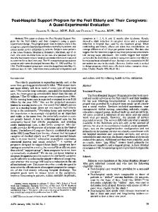
Figure 1. (a) Principle of actuation of the digital microflow regulator. (b) Picture of an array of V-shaped beams (top). Twelfth International Conference on Miniaturized Systems for Chemistry and Life Sciences October 12 - 16, 2008, San Diego, California, USA 978-0-9798064-1-4/µTAS2008/$20©2008CBMS
1684
This is a problem in drug delivery systems or micro-dialysis devices because the flow rate is a critical parameter. In order to avoid this dependence of the pressure fluctuations, active flow regulation is used. This work proposes a novel externally actuated, digital micromachined flow regulator based on an array of magnetically actuated fluidic switches [1]. The micro-fluidic switch has two parts: top V-shaped cantilever which opens or closes the flow path and the bottom membrane with a hole which at each pressure limits the output flow. The total flow is determined by the magnet position that opens a certain number of individual switches, see Figure 1. FEA MAGNETO-STRUCTURAL ANALYSIS The effect of the magnet position on the different V-shaped beams has been studied through a FEA multiphysics model using a coupled field direct magnetic/structural analysis. From all possible positions of the magnet in X direction, the best option to place the magnet is at X=500 μm, in this case when the magnet is at the position 1(both switches interact with the magnet), both of them are open (Z is positive), at position 2 (only switch 2 interacts with the magnet) switch 1 is closed and switch 2 is open and at position 3 (no interaction) all of them are closed.
Figure 2. (a) Elements in the model (magnet+CoNi/Si frame). Deflection of the two switches with the magnet (b) at X=– 500 μm (c) centered (d) at X=500 μm. EXPERIMENTAL RESULTS The microflow regulator (top: array of V-shaped beams and bottom: membrane with holes) is manufactured using a combination of silicon micromachining technologies and electro-deposition of a magnetic CoNi alloy [2]. Both parts are mounted using an epoxy H70 Epotek cured at 120ºC. The microflow regulator is Twelfth International Conference on Miniaturized Systems for Chemistry and Life Sciences October 12 - 16, 2008, San Diego, California, USA
1685
placed on a flat substrate that aligns the magnet with the array of switches and this is moved thanks to a micromanipulator. A pressure generator (DI 1515) is used to provide a flow of N2 gas at the desired pressure to the inlet of the microflow regulator. At different magnet positions, the output flow is measured with a flowmeter (AWM300) which provides a voltage proportional to the flow rate.
Figure 3. Measured N2 flow through the micro- regulator at different pressures, with the magnet position switched from the first to the forth microfluidic switch. Initially the fluidic force closes the array of cantilevers, then the magnet is placed on the top of the microflow regulator. If all cantilevers interact with the magnet, the flow is the maximum that the output holes allow at the applied pressure. In Figure 3, a N2 flow was regulated at different pressures [40-140 mbar] showing that when the magnet is moved along the microflow regulator the maximum flow at each pressure is proportional to the number of open switches and it decreases approximately 1 sccm every time that a switch is closed. CONCLUSIONS In this paper a novel microfluidic flow regulator has been analyzed, fabricated and tested. The flow regulator can “quasi-digitally” control a microflow to a set of predetermined values. This structure can be miniaturized even further to achieve a more extended range of possible output flows. REFERENCES [1] J. Casals-Terré, M. Duch, J. A. Plaza, J. Esteve, R. Pérez-Castillejos, E. Vallés and E. Gómez. Design, fabrication and characterization of an externally actuated ON/OFF microvalve. Sensors and Actuators A. Accepted for publication 2008. [2] M Duch, J Esteve, E Gomez, R Perez-Castillejos and E Valles. Journal of Micromechanics and microengineering. Vol 12 2002. pp. 400-405. Twelfth International Conference on Miniaturized Systems for Chemistry and Life Sciences October 12 - 16, 2008, San Diego, California, USA
1686