Sam Ben-Yaakov and Mor Mordechai Peretz .... [3] D. Medini and S. Ben-Yaakov, âA current controlled variable inductor .... Alternative Energy, Liuchen Chang.
IEEE Power Electronics Society NEWSLETTER, Fourth Quarter 2003
9
Simulation Bits: A SPICE Behavioral Model of Non-Linear Inductors© Sam Ben-Yaakov and Mor Mordechai Peretz SPICE simulation is already recognized as a viable tool in Power Electronics. Simulation is particularly useful when dealing with a non-linear behavior that cannot be easily handled analytically. Such a case is the analysis of a switching power converter that includes a non-linear inductor that might affect the inrush current, magnitude of the current ripple, small signal transfer functions and others. Modern SPICE simulation packages, such as ORCAD (Cadence, CA, USA) include a non-linear magnetic core model that is based on the Jiles and Atherton model [1]. However, unless the vendor already provides a model for a given core, developing your own model for your specific application may prove to be very frustrating if not practically impossible. Here we demonstrate how a SPICE compatible behavioral model of a non-linear inductor can be developed easily using core manufacturer’s data or simple laboratory measurements. The resulting model is by no means perfect. It does not include core losses, temperature effects, or frequency dependence of the permeability, and it does not show the hysteresis effect. Nonetheless, one may still find it useful in many applications such as the examination of the current ripple of iron powder core inductors under various operating conditions or in small signal analysis based an behavioral average modeling [2]. The basic idea of the proposed inductor model is to reflect the behavior of a linear inductor via a non-linear ‘transformer’ that is realized by (E1, G1) dependent sources (Fig. 1) defined by: E1 ≡ Vpr
1 = Vsec K
L'
E1
+ -
I DC
Isec Vsec
L
The impedance XL of the original inductor L is defined as:
Vsec I sec
=
K V sec
= K XL
L AUX
Figure 1. A non-linear inductor model built by reflecting a linear inductor via a non-linear ‘transformer.’
XL =
V pr
(3)
K=
µ0 n 2 Ae µr ( H) L eng
(6) I pr I sec Consequently, the inducV_Ipr tance L' reflected to the priV_Isec G1 GVALUE E1 EVALUE + mary side, expressed in terms 1 0VDC + I(V_Isec) V(%IN+, %IN-)/V(k) 0VDC L1 V pr+ of K, is: OUT+ IN+ IN+ OUT+ 1H V prOUT- INR2 2 0 (5) IN- OUTL' = L × K If K is made dependent 0 1u E2 ETABLE k IN+ OUT+ on the current through the inIN- OUTductor (or through a bias windR1 1meg I(V_Ipr) ing [3]), then the model will emulate the non-linearity of the 0 device. In the modern SPICE Figure 3. A non-linear inductor SPICE model environment, one could use bebased on measured inductance values. The table havioral dependent sources in of the ETABLE dependent source lists the which the dependence of K on measured inductance as a function of dc current. the current can be defined as an expression (‘EVALUE’ or Analog Behav- where µ is the air permeability, A is the 0 e ioral Model ‘ABM’ dependent sources in effective magnetic area of the core, L is eng ORCAD) or a table (‘ETABLE’ element in the effective magnetic length of the core , n ORCAD). The two approaches are demon- is the number of turns, and µ (H) is the relar strated by considering two cases: one based tive permeability as a function of the magon simple laboratory measurements that map netic field H. the non-linearity of the device, and the other Core manufacturers provide the µr(H) using manufacturer’s data. information as graphs or experimental equaMethod A – Experimental Fitting. In tions. If an equation is not given then the this case, one has first to carry out (incre- graph data could be fitted to an experimenmental) inductance measurements on the tal equation or described as a table. In the physical inductor, over the expected range latter case one can use again the ETABLE of inductor current. Subjecting the induc- element. If the equation is available then it tor to a dc current (IDC) via an auxiliary in- can be used as an expression in an EVALUE ductor (LAUX), and applying a signal generaor ABM element. For example, the experitor (VAC) to measure the small-signal impedmental equation given by Magnetics [4, 5] ance of the tested inductor (VL/IL) could easfor Kool Mu cores is (after some streamlinily accomplish this (Fig. 2). ing):
(2)
G1
Vpr
' = XL
Method B – Fitting to Manufacturer’s Data. In this case and for L = 1 H, K is defined by the inductance equation:
(4)
CC
(1)
G1 ≡ I sec = I pr
Ipr
Based on Eqs (1) – (3), the inductor impedance X L' reflected to the primary side is:
C1 + VAC
TAC
µ r (H ) = µ i
IL
C2 L DUT
VL
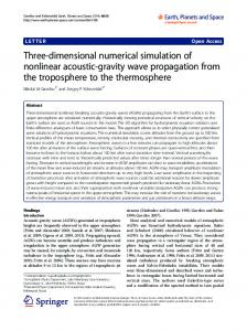
Figure 2. Experimental setup for measuring the small signal impedance of a dc biased inductor. The results of the inductance measurements are then inserted in the ETABLE element to form the model of the non-linear inductor (Fig. 3). Notice that for simplicity L is made equal to 1 H and the values listed in ETABLE correspond to the measured inductances.
1 − 5.618 × 10⁻⁵ β + 1.043 × 10⁻¹⁰ β 2 1 + 6.742 × 10⁻⁵ β + 6.21×10 −8 β 2
(7) where µi is the initial relative permeability, β =µi H, and H is the magnetic force in Oersted units (1 Oe ≈ 80 Amp-turn/m). The magnetic force H is in turn a function of the magnetizing current I: H=
nI L eng
(8)
Using this experimental equation (7) along with Eqs (6) and (8) one can easily construct a SPICE model for an inductor that is built around this core (Fig. 4). Continued on page 10
IEEE Power Electronics Society NEWSLETTER, Fourth Quarter 2003
10
Non-linear Inductor
from page 9
The proposed model of a non-linear inductor is compatible with all basic SPICE V_Ipr + 1 0VDC
V pr+
2
V pr-
E2 EVALUE IN+ OUT+ IN- OUT-
ABM1
k
E1 EVALUE V(%IN+, %IN-)/V(k) 0
IN+ OUT+ IN- OUT-
+ 0VDC
L1
R2
1H
0 1u
H
(n*I(V_Ipr))/(Leng*80) R1
Biographies
V_Isec
G1 GVALUE I(V_Isec) OUT+ IN+ OUT- IN-
[5] Powder Core Data, Magnetics, PA, USA http://www.mag-inc.com/pdf/ MAGNETICS_Powder_Core_Data.pdf
1meg
V(H)*Mu_i beta
0
(pwr(n,2)*Mu_0*Ae/Leng)*Mu_i* sqrt((1-56.18u*V(beta)+104.3p*pwr(V(beta),2)) /(1+67.42u*V(beta)+62.1n*pwr(V(beta),2)))
PARAMETERS: n = 130 Mu_i = 125 Mu_0 = {4*3.14*1e-7} Ae = {1.0726*1e-4} Leng = 0.0984
Shmuel (Sam) BenYaakov is a Professor at the Department of Electrical and Computer Engineering, Ben-Gurion University of the Negev, BeerSheva, Israel and heads the Power Electronics Group there. He can be reached at .
Figure 4. A non-linear inductor SPICE model based on manufacturer’s data (Eq. 7) for a 77254A7 Kool Mu iron powder core. H is calculated in MKS units and then divided by 80 to get it in Oe units as required for Eqs (7) & (8). analyses (DC, AC, TRAN). We have found it to reproduce faithfully the behavior of the physical core in practical applications. The method can be easily extended to cores with separate dc bias windings [3] and to represent the non-linearity of the magnetization inductance of transformers. SPICE/ORCAD files (Evaluation Version 9.2) that include examples of the proposed inductor model can be downloaded http://www.ee.bgu.ac.il/~pel/ from download.htm.
References [1] D. C. Jiles and D. L. Atherton, “Theory of ferromagnetic hysteresis,” Journal of Magnetism and Magnetic Materials, vol. 61, pp. 48-60, 1986. [2] I. Zafrani, S. Ben-Yaakov, “Generalized switched inductor model (GSIM): accounting for conduction losses,” IEEE Trans. Aerospace and Electronic Systems, vol. 38, pp. 681-687, 2002. [3] D. Medini and S. Ben-Yaakov, “A current controlled variable inductor for high frequency resonant power circuits,” in IEEE Applied Power Electronics Conference, APEC’94, pp. 219-225, Orlando, 1994. [4] Powder Core Technical Data, Magnetics, PA, USA Available: http:// www.mag-inc.com/pdf/ MAGNETICS_Powder_Core_Technical _Data.pdf
Mor Mordechai Peretz is a M.Sc. student at the Ben-Gurion University of the Negev, BeerSheva, Israel. He can be reached at . Mail Address (both authors): Power Electronics Laboratory Dept. of Electrical and Computer Engineering Ben-Gurion University of the Negev 1 Ben-Gurion Ave Beer-Sheva 84105 ISRAEL
President’s Message
from page 3
In order to provide for this kind of granularity, my predecessor Tom Habetler decided to develop our technical committees, something which I soon saw was of great value in supporting our members, and something which I also should pursue. Thus within the short space of 2 years we have gone from 6 committees to 11, and we are busily working to get them all set up with “effectiveness for our members” as the primary criterion. So what goes on in a technical committee? We have deliberately left that without a lot of fine detail—no rules, regulations, briefs, or terms of reference—leaning rather to guidelines, with an overarching goal that they provide easy and productive ways for interaction between our members in each of these subspecialties. To put all that in perspective, here is a list of our current technical committees including two very new ones approved by our ADCOM at the IAS annual meeting in Salt Lake City in October 2003.
Distributed Inverters
from page 8
Stricter and better-defined specifications for small, distributed power inverters in relation with the background voltage distortion and harmonic levels in networks are required. For more information and technical results as well as some practical guidelines, see the reference below. [1] J.H.R. Enslin and P.J.M. Heskes, “Harmonic Interaction between a Large Number of Distributed Power Inverters and the Distribution Network,” in Proceedings 34 th IEEE Power Electronics Specialists Conference, Acapulco, Mexico, June 15 – 19, 2003. Johan HR Enslin (M’85, SM’92) is currently a principal consultant with KEMA T&D Consulting in Raleigh, NC, USA. He received the B.Eng, M.Eng and D.Eng. degrees in Electrical and Electronic Engineering from the Rand Afrikaans University), South Africa, in 1981, 1983, and 1988 respectively. His consulting and research interests include renewable energy, power quality, reactive power compensation, and power electronics. He has written and coauthored more than 150 papers, of which seven received prize-paper awards. He holds nine patents and has presented several short courses. Dr Enslin is a Registered Professional Engineer, an IEEE Senior Member, and a member of the South African Institute of Electrical Engineers.
PELS Technical Committees • Automotive Power Electronics, John Shen • DC Power Supply Systems, Jose A. Cobos • Electronic Transformers, Bill Goethe • Motor Drives, Alfio Consoli • Power Packaging, Douglas Hopkins • Rectifiers and Inverters, Fang Peng • Simulation, Modeling & Control; Antonello Monti • Education, Leon Tolbert • Telecommunications Energy, Mark Jacobs , Katsuichi Yotsumoto • PE for Distributed Generation / Alternative Energy, Liuchen Chang Continued on page 12