oriented parallel software development environment is presented. This development environment is composed of a graphical design tool, a sim- ulation facility, and a ..... Drive, Austin TX 78746, February 1992. 17] N. Shacham and V. B. Hunt.
Simulation Modelling of Parallel Systems in the EDPEPPS� Project Thierry Delaitre, Fran� cois Spies, & Stephen Winter
Centre for Parallel Computing, University of Westminster London, United Kingdom
Abstract
In this paper, a simulation model for incorporation within a performanceoriented parallel software development environment is presented. This development environment is composed of a graphical design tool, a simulation facility, and a visualisation tool. Simulation allows parallel program performance to be predicted and design alternatives to be compared. The target parallel system models a virtual machine composed of a cluster of workstations interconnected by a local area network. The simulation model architecture is modular and extensible which allows a re-con guration of the platform such as the hardware layer. The model description and the validation experiments which have been conducted to assess the correctness and the accuracy of the model are presented.
1 Introduction The key obstacle to the widespread adoption of parallel computing is the dif culty in program development. Firstly, an application has to be decomposed into parallel objects (processes, or tasks) according to the computational model underlying the programming language. Secondly, the parallel hardware con guration has to be speci ed. Finally the processes are then mapped onto the hardware. The range of design choices available to the parallel program designer at each of the three stages can be immense. This has tended to produce highly-optimised platform-speci c solutions, which are not easily ported to other platforms. A lot of work has been done to create standard and relatively user-friendly interfaces at the message-passing layer, enabling programmers to decompose their applications into standardised processes which will run on a wide range of hardware (o�ering the standard message-passing platform). In principle, a program developed for a cluster of workstations should run correctly on a distributed-memory multiprocessor machine such as an SP2. Parallel Virtual Machine (PVM) [1] is such a message-passing environment, widely used by researchers and engineers, which permits a heterogeneous collection of networked computers to be viewed by an application as a single distributed-memory parallel machine. However, developing a high performance parallel application remains a specialist task, since parallel programs present complex modes of � This project is funded by an EPSRC PSTPA programme, Grant Number : GR/K40468 and also by EC Contract Num: CIPA-C193-0251, CP-93-5383
1
behaviour which are di�cult to predict a priori. In particular, the issues of partitioning the application into processes, and subsequently mapping those processes onto processors of the target computer system, to achieve optimal performance, remains the responsibility of the program designer. Optimality of performance is not guaranteed following a port to another platform, which may have very di�erent characteristics. In essence, the application must be re-engineered for every platform. The problems can be exacerbated in the case of network programming, where there is a need to account for the variable workload of the network which is not dedicated exclusively to the processing of a single application. Rapid prototyping is a useful approach to the design of high-performance software in that algorithms, outline designs, or even rough schemes can be evaluated at a relatively early stage in the development life-cycle, with respect to possible platform con gurations, and mapping strategies. Modifying con gurations and mappings will permit the prototype design to be re ned, and this process may continue in an evolutionary fashion throughout the life-cycle. Appropriate techniques for evaluating performance are required at each iteration however. There are three principle approaches to performance evaluation of a distributed application: measurement, analytical modelling and simulation [2]. Measurement can only be achieved on existing systems and results are a�ected by a range of run-time environmental factors arising within the system and the measurement process itself. Analytical modelling { the development and study of models whose solutions are tractable to mathematical techniques { enable exact descriptions of system behaviour to be developed, but restrictions on system functionality and workload must usually be introduced to make the model solvable, resulting in loss of accuracy. Simulation { of models which are often analytically intractable { overcomes both these di�culties, enabling the behaviour of arbitrarily complex software and hardware systems to be tracked to any level of detail. Modelling abstractions are needed only to improve the performance of the simulation, but these are generally less restrictive than in the case of the analytical approach. Simulation thus helps the designer to identify those components which limit the capacity of the system (bottlenecks), and allows performance estimates of the application from the early stage of its conception to be obtained. In the next section, we describe the state of the art on modelling tools. Then, in section 3, we present the technique used for developing simulations. Finally, our simulation model is presented and its validation in sections 4 and 5.
2 Parallel System Performance Modelling Tools The current trend for parallel software modelling tools is to support all the software performance engineering activities in an integrated environment [3].
A typical toolset should be based on at least three principal tools: a graphical design tool, a simulation facility, and a visualisation tool. The last should coexist within the same environment as the rst to allow information about the program behaviour to be related to its design. Many existing toolsets are comprised of only a subset of these tools and often, visualisation is a separate tool. The target parallel system is typically a transputer-based multiprocessor machine and the modelling of the operating system is usually not addressed (except in the PEPS toolset [4]). One of the earliest toolsets for parallel programmingwas the Transim/Gecko [5, 6] toolset, developed under the Parsifal project at the University of Westminster. The designer can rapidly evaluate di�erent designs of an occam-like program running on transputer-based multiprocessor with an animation-based representation of the resulting trace. Also, Gecko allows occam processes to be remapped graphically and to re-simulate the application. The Transim/Gecko approach has been the model for simulation based environment projects such as MIMD [7, 8] at the University of Edinburgh. MIMD (Multiple Instruction stream, Multiple Data stream) is a modelling environment to study the performance of parallel programs. MIMD is built on top of DEMOS [9] and Simula. DEMOS is an extension to Simula which contains classes suitable for discrete event simulations. MIMD provides classes for modelling message passing parallel programs on distributed memory architectures. The existing classes allow occam programs running on Transputer machines to be modelled. Both toolsets have similar features in common except that in MIMD an experimental framework has been de ned in order to investigate the e�ects of varying certain parameters characterising a parallel program on its run-time behaviour. A more recent toolset, the HAMLET Application Development System [10] is a development environment for real-time applications based on transputers (primarily) and PowerPCs. The HAMLET toolset combines graphical design tools, simulation techniques, and performance traces. In particular, it consists of a design entry system, DES, a speci cation simulator, HASTE, a debugger and monitor, INQUEST, and a trace analysis tool, TATOO. The DES tool generates the design used for simulation which is identical with the design for target code generation. A key feature of HAMLET is the ability to produce a code suitable for the simulator and a code suitable for real execution from the same graphical design. Also, performance traces obtained from the simulation and from the monitoring tools have the same format, therefore the visualisation tool is suitable for simulation and monitoring. The limitation of this tool is with its hardware and software libraries which are restricted to transputers and PowerPCs. Another toolset developed at the University of Vienna is the PAPS toolset [11] (Performance Analysis of Parallel Systems) which aims to predict the performance of parallel programs running on parallel transputer architectures. The input models are the parallel program represented as a directed task graph, the speci cation of the multiprocessor system and a description onto which processor each task graph is mapped. The PAPS toolset automatically generates a discrete deterministic timed Petri net out of the parallel system speci cation. The simulation of the Petri net model produces a trace
Simulator file
Graphical Design
Graphical Application file
Visualisation
trace file
simulation
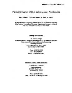
Figure 1: The EDPEPPS Architecture. le and some statistical information about the program execution. The major di�erences between PAPS and the toolsets cited above are that the input models and the simulation model use a di�erent formalism. Moreover some statistical information about the program execution is produced. In the next projects, the target parallel system is assumed to be a virtual machine whereas the previous toolsets assume a physical machine. The PEPS project [4] aims to investigate benchmarks, modelling, characterisation, and monitoring of PVM programs for Transputer-based platforms. The aim of performance modelling in PEPS is to develop a tool for the performance evaluation of computer architectures. PEPS uses the Simulog simulation toolset including MODARCH which o�ers a range of software and hardware components. The library of objects allows PVM programs running on a network of transputers to be modelled. In this case, the model of PVM is much simpler than PVM within a heterogeneous distributed computing environment in which all nodes share a single communication medium and where contentions occur. One of the major challenges in PEPS is the modelling of the micro-kernel on each transputer. Also, a similar experimental framework such as in MIMD is provided. The SEPP project [12, 13] (Software Engineering for Parallel Processing) has developed an overall architecture based on ve principal tool types: Static Design Tool; Dynamic Support Tools; Behaviour Analysis Tools; Simulation Tools; and Visualisation Tools. The programming model is a subset of the PVM programming paradigm.
3 Simulation in EDPEPPS EDPEPPS [14] (Environment for Design and Performance Evaluation of Portable Parallel Software) is a tool research project at the University of Westminster which intermeshes with the SEPP project. EDPEPPS is based on a rapid prototyping philosophy, in which the designer synthesizes a model of the intended software, which may then be simulated, and the performance subsequently analysed using visualisation. The toolset combines a graphical design tool (PVM-
PVM Applications PVMD
LIBPVM
Application Layer Message-passing Layer
System Call Interface Process Scheduler
Socket Layer
Operating System Layer Transport Layer Network Layer
System Resources
Hardware Layer
Figure 2: Simulation model architecture. Graph), a simulation facility, and a visualisation tool (PVMVis). The same design is used to produce a code suitable for simulation and for real execution. The results of simulation are an event trace le and some statistical information about the virtual machine. The graphical design tool is based on the PVM programming model. Simulation of the PVM platform in EDPEPPS is built using the state of the art simulation environment, SES/WorkbenchTM [15, 16]. Simulation in EDPEPPS is based on discrete-event modelling { a technique well-proven in the simulation of computer hardware and software. Discreteevent models underpin Transim for example, which achieves a remarkable degree of accuracy. The technology is well-established, and sophisticated modelling tools are available commercially. SES/Workbench, has wide functionality meeting the requirements of computer system modelling, a time-saving graphical design interface, and animation-based visualisation capabilities. Techniques for parallelising discrete-event simulation programs are well-established, thus providing a route for optimising the run-time performance of the simulator. The workbench is used both to develop, and simulate platform models. Thus the simulation engine in the workbench is an intrinsic part of the prototype EDPEPPS toolset. The design of the platform simulator is described in the following sections. After developing our simulation model, a veri cation and validation step is necessary, in order to be sure that it gives relevant performance evaluation of the real system. Parts of our model validation have been conducted from the system resources layer to the application layer. Validation takes the forms of comparative measurement. In the case of Ethernet we compare our results against published measurements [17, 18].
4 Simulation model The EDPEPPS simulation model consists of the PVM platform model library and the PVM programs for simulation. The PVM platform model is parti-
tioned into three layers (Figure 2): the message passing layer, the operating system layer and the hardware layer. Modularity and extensibility are two key criteria in simulation modelling, therefore layers are decomposed into modules, which permits a re-con guration of the entire PVM platform model. The initial modelled con guration consists of a PVM environment which uses the TCP/IP protocol, and a cluster of heterogeneous workstations connected to a single 10 Mbit/s Ethernet network. A PVM program generated by the PVMGraph graphical design tool, is translated and passed to the workbench, where it is integrated with the platform model in readiness for simulation. The next section de nes the interface between PVMGraph and Workbench which is the SimPVM language.
4.1 SimPVM { A Simulation Oriented Language
PVMGraph allows PVM applications to be developed using a combination of graphical objects and text. From this description, executable PVM programs may be generated, but to simulate program execution, annotations must be inserted into the graphical/textual source to control the simulation. This allows both an executable and a \simulatable" version of the program to be generated from the same graphical/textual source. All simulation models in EDPEPPS are based on queueing networks. The \simulatable" code generated by PVMGraph is predominantly a description of the software rather than the execution platform. To simulate the application, a model of the intended platform must be available. Thus, a simulation model is fundamentally partitioned into two submodels: a dynamic model automatically generated from the PVMGraph description, which is comprised of the application software description and some aspects of the platform (eg. number and type of hardware nodes); and a static model which represents the underlying parallel platform, to a suitable level of detail. By building the static descriptions into the simulation system itself, the service is transparent to the application designer, yet provides a virtual, simulation platform for the generated application. The SimPVM language basically contains the following elements: � the list of processes to be initially executed (exec), and the host (identi cation) number where they execute; � the description of processes (process) and functions (function). In this version, processes cannot be parameterised; � C instructions for variables declaration, loops (for and while), conditional instructions (if else), and assignments; � PVM functions for process management (e.g. pvm mytid and pvm spawn), bu�er management (e.g. pvm getsbuf) and for point-to-point communication (e.g. pvm send); � simulation constructs such as computation delay function and statistical variables.
exec Master(0,1); process Slave() { int mytid, i; mytid=pvm_mytid(); for (i=0; i