Proceedings of the World Congress on Engineering 2007 Vol II WCE 2007, July 2 - 4, 2007, London, U.K.
Simulation of IEEE 802.11e in the Context of Interoperability Orlando Cabral, Alberto Segarra, Fernando J. Velez, Member, IAENG
Abstract— This work provides the specification of a MAC layer simulator that evaluates the service quality in WiFi, and presents initial results as a stand-alone simulator. The simulator will account for inter-working with WiMAX and HSDPA in the context of the IT-MOTION tool. Higher throughputs are found for the FTP service and for the video service, mainly because the frames transmitted in these services are longer than the ones for the voice application. However, the number of supported users is higher for voice. This simulator will allow for tuning-up several parameters like the ones related to how to use BlockACK, normal ACK, and NO ACK policies. Index Terms—QoS, simulation, IEEE 802.11e, interoperability.
I. INTRODUCTION Under the paradigm of wireless systems coexistence, recent theoretical developments have targeted cross-layer design as the key to efficiently exploit the available spectral resources. Strong interactions exist between the channel environment conditions with the networking issues of resource allocation. This suggests that several problems which are traditionally considered as networking issues, and are typically designed independently of the transmission techniques need to be re-examined, and therefore cross-layer design and optimisation will be the way forward. Also, in the presence of heterogeneous systems, this concept can be further exploited to include cross-system parameters. Therefore, it is important to investigate cross-layer and cross-system optimisation for legacy and future wireless systems. The sought solutions will give strong contributions to innovative cellular planning solutions and network development tools that consider interoperability via the integration of coexistence protocol libraries that will make demonstrations possible. The fast development and deployment of multimedia wireless and mobile communication systems B3G will be mainly driven by multimedia traffic, and research on network design and multi-service traffic aspects will be strategic. Furthermore, heterogeneous mobile and wireless networks are nowadays available in the market, with totally different characteristics and dimensioning approaches. The research Manuscript received March 22, 2007. Orlando Cabral, Alberto Cabral, and Fernando Velez are with the Instituto de Telecomunicações, University of Beira Interior, Covilhã, Portugal (phone: +351 275329953; fax: +351 275329972; e-mail:
[email protected],
[email protected],
[email protected]).
ISBN:978-988-98671-2-6
community is now directing its interest towards new ways of optimising not only each system individually, through cross-layer design in the context of All-IP networks but also of achieving cross-system optimisation, making the simultaneous use of systems with totally different access technologies transparent to the user. Innovative architectures and protocols will be proposed for this coexistence, and mechanisms to guarantee the QoS will be explored, including MAC layer solutions. Since there are totally different protocols and requirements in each system, a harmonized solution is sought. Aspects like mobile IP, network discovery and session management, intersystem handover, and dynamic resource allocation are being addressed. One of the final objectives will be the development of a network development tool that accounts for several mobile communication systems. The aim of this work is to provide the specification of a MAC layer simulator that evaluates the service quality in WiFi in order to enable simulations accounting for inter-working with WiMAX and HSDPA in the context of the IT-MOTION tool [1], and to improve scheduling algorithms and Common Radio Resource Management (CRRM) techniques. Apart from a brief presentation of the state of the art on the interoperability among wireless system in Section II, this work describes the development of a IEEE 802.11e simulator to be incorporated into the IT-MOTION tool. The description of the IEEE 802.11e standard and from Hybrid coordination function enhanced distributed channel access from Sections III and IV is followed by a brief presentation of the state transition diagram, its variables, entities, and functions, Section V. Section VI addresses the hypothesis from system and scenario while Section VII presents simulation results. Conclusions are presented in Section VIII as well as future work. II. STATE OF THE ART In order to support accurate B3G network radio planning and system optimisation there is a need for a flexible and open evaluation tool that provides a framework to support cross-system simulations in a cost-effective manner. By its nature, simulation evaluation tool design is a challenging task in an effort to provide a trade-off between accurate system modelling, and complexity, which will adversely effect the simulation time. Network throughput can benefit from cross-layer design techniques. Although layering is today the driving methodology, strict layering principles may result in inefficient implementations of B3G wireless networks.
WCE 2007
Proceedings of the World Congress on Engineering 2007 Vol II WCE 2007, July 2 - 4, 2007, London, U.K.
Moreover, specific issues in wireless networks (e.g. radio resource shortage, power restriction consumption, etc.) call for further optimisations in network performance. From the cross-layer perspective, significant attention is given to the interfacing methodology between PHY, MAC, network and transport layer. Typically, protocol evaluation platforms are not managed by the same task manager/processor, otherwise computation time would be prohibitive. Thus, interfacing is usually managed by look-up tables that are computed off-line. The traditional problem is how to reflect the physical layer assumptions, implications, and scenarios on the system level when independent simulation platforms with different time granularities are employed. References. [2], [3], [4] have addressed these issues, and [5] is targeting the link level interface, given MTMR (Multiple Transmit Multiple Receive) techniques for MIMO (Multiple-Input-Multiple-Output) MC-CDMA. How to model the interface assuming coexisting systems is a research challenge that needs to be further explored. From the cross system perspective, EVEREST (Evolutionary Strategies for Radio Resource Management in Cellular Heterogeneous Networks) [6] project aims at providing advanced Radio Resource (RRM) and Quality of Service (QoS) Management solutions for the support of mixed services within the context of heterogeneous networks beyond 3G. Specifically it aims to address inter-working of UMTS, GERAN and WLAN RRM entities using a bandwidth broker at the Core Network (CN). ROMANTIK (Resource Management and Advanced Transceiver Algorithms for Multihop Networks) [7] tackled "structured" and "ad-hoc" multi-hop radio networks as well as intelligent relaying techniques for B3G mobile/wireless communication systems. Also ARROWS (Advanced Radio Resource Management for Wireless Services) [8] developed, simulated, evaluated and validated advanced Radio Resource Management algorithms and procedures for an optimal and efficient use of the radio resources provided by UTRA to enable high capacity for multi-service applications requiring high bit rate (up to 2Mbit/s). Both TDD and FDD modes were considered. Furthermore, research has also targeted interoperability between WLAN, and 3G [9], [10]. This is deemed an important system relationship as both have a common scenario that can support multimedia traffic in indoor environment. Research trends are driving towards resource allocation solutions that can facilitate explicit control in packet scheduling [11], [12] to allow optimal use of radio resources by using cross-layer information, which can include session QoS statistics, channel state information and MIMO [5]. The requirements on link radio delay, (end-to-end) latency, bit error rate, data rates, and traffic characterisation need to be identified for mobile multimedia network beyond 3G. In [13] characterisation parameters were identified and values were suggested for their range of variation, in the context of cross-layer design, including a resource allocation parameter, very useful for optimisation based on utility functions. The joint utilisation of multiple alternate radio technologies
ISBN:978-988-98671-2-6
can provide capacity enhancements inside areas where a single stand-alone radio network segment cannot confront the totality of traffic demands and extended radio coverage in cases where possibly due to the user’s mobility, the signal of the wireless network currently in use is lost or degraded. A relevant example, regarding the discussed cooperation among heterogeneous network segments, is the efficient serving of users through seamless and transparent handover both inside and outside of hot-spot areas. For example, the WLAN technology offering high throughput and short-range capabilities can be employed inside hot-spots, while a 3G technology, featuring wider coverage and lower bandwidth characteristics, can be used for supporting lower data traffic streams outside of hot-spots. Motivation for the seamless integration of wireless network technologies is further promoted by the fact that, from a high-level viewpoint, many aspects of heterogeneous wireless networks are invariant to the underlying radio technology actually employed, which becomes irrelevant for the service providers (SPs) and the users, as long as cost and quality criteria are met. This invariance can be further sustained and promoted through the use of suitable intelligent multi-mode terminals, possibly in conjunction with advanced resource and service management systems. III. IEEE 802.11E The IEEE 802.11 architecture consists of several components that interact to provide a wireless LAN that supports station mobility transparently to upper layers. The basic service set (BSS) is the basic building block of an IEEE 802.11 LAN. Fig. 2 shows two BSSs, each of which has two stations that are members of the BSS. Instead of existing independently, a BSS may also form a component of an extended form of network that is built with multiple BSSs. The architectural component used to interconnect BSSs is the distribution system (DS). IEEE 802.11 logically separates the wireless medium (WM) from the distribution system medium (DSM). Each logical medium is used for different purposes, by a different component of the architecture. An access point (AP) is a station (STA) that provides access to the DS by providing DS services in addition to acting as a STA Data move between a BSS and the DS via an AP, Fig. 1.
Fig. 1 - Non-roaming reference model. The IEEE 802.11 quality os service (QoS) facility provides medium access control (MAC) enhancements to support local area network (LAN) applications with QoS requirements. The QoS enhancements are available to QoS stations (QSTAs) associated with a QoS access point (QAP) in a QBSS.
WCE 2007
Proceedings of the World Congress on Engineering 2007 Vol II WCE 2007, July 2 - 4, 2007, London, U.K.
The mechanism called the enhanced distributed channel access (EDCA) delivers traffic based on differentiating user priorities (UPs), Fig. 2. This differentiation is achieved by varying the following for different UP values: • Amount of time a STA senses the channel to be idle before backoff or transmission, or • The length of the contention window to be used for the backoff, or • The duration a STA may transmit after it acquires the channel. The mechanism called the hybrid coordination function (HCF) controlled channel access (HCCA) allows for the reservation of transmission opportunities (TXOPs) with the hybrid coordinator (HC), Fig. 2. Details on the CSMA/CA protocol, and interframe spaces (IFS) are presented in [14]. The backoff time and the backoff procedure are addressed in [14] and [15], as well as he description of the network allocation vector (NAV), and the use of RTS/CTS with fragmentation, the fragmentation is the process of partitioning a MAC service data unit (MSDU) or a MAC management protocol data unit (MMPDU) into smaller MAC level frames, MAC protocol data units (MPDUs). Required for Prioritized QoS Services Required for Contention Free Services for nonQoS STA; optional othewise
MAC Extent
Lowest
Highest
UP (Same as 802.1D
802.1D
user priority)
Designation
1 2 0 3 4 5 6 7
BK — BE EE CL VI VO NC
AC
Designation
AC_BK AC_BK AC_BE AC_BE AC_VI AC_VI AC_VO AC_VO
Background Background Best Effort Best Effort Video Video Voice Voice
Required for Parametrized QoS Services Hybrid Coordination Function (HCF)
Point Coordination Function (PCF)
HCF Contention Access (EDCA)
HCF Controlled Access (HCCA)
Used for Contention Services: basis for PCF and HCF
Distributed Coordination Function (DCF)
Fig. 2 - MAC architecture. IV. HYBRID COORDINATION FUNCTION (HCF) ENHANCED DISTRIBUTED CHANNEL ACCESS (EDCA) The QoS facility includes an additional coordination function called HCF that is only usable in QoS network (QBSS) configurations. The HCF shall be implemented in all QSTAs. The EDCA mechanism provides differentiated, distributed access to the WM for QSTAs using eight different UPs. The EDCA mechanism defines four access categories (ACs) that provide support for the delivery of traffic with UPs at the QSTAs, Fig, 3. The AC is derived from the UPs as shown in Table I. For each AC, an enhanced variant of the DCF, called an enhanced distributed channel access function (EDCAF), contends for TXOPs using a set of EDCA parameters from the EDCA Parameter Set element or from the default values for the parameters when no EDCA Parameter Set element is received from the QAP of the QBSS with which the QSTA is associated.
Table I - UP to AC mappings.
ISBN:978-988-98671-2-6
Fig. 3 - The ACs in EDCA [17]. The TXOP limit duration values are advertised by the QAP in the EDCA Parameter Set information element in Beacon and Probe Response frames transmitted by the QAP. Non-AP QSTAs shall ensure that the duration of TXOPs obtained using the EDCA rules do not exceed the TXOP limit. The duration of a TXOP is the duration during which the TXOP holder maintains uninterrupted control of the medium, and it includes the time required to transmit frames sent as an immediate response to the TXOP holder’s transmissions. 1) Obtaining an EDCA TXOP Each channel access timer shall maintain a backoff function (timer), which has a value measured in backoff slots. The duration AIFS[AC] is a duration derived from the value AIFSN[AC] by the relation AIFS[AC] = AIFSN[AC] × aSlotTime + aSIFSTime The value of AIFSN[AC] shall be greater than or equal to 2 for non-AP QSTAs and is advertised by the QAP in the EDCA Parameter Set information element in Beacon and Probe Response frames transmitted by the QAP. The value of AIFSN[AC] shall be greater than or equal to 1 for QAPs. An EDCA TXOP is granted to an EDCAF when the EDCAF determines that it shall initiate the transmission of a frame exchange sequence. Transmission initiation shall be determined according to the following rules: - On specific slot boundaries, each EDCAF shall make a determination to perform one and only one of the following functions [14]:
WCE 2007
Proceedings of the World Congress on Engineering 2007 Vol II WCE 2007, July 2 - 4, 2007, London, U.K.
• Initiate the transmission of a frame exchange sequence for that access function. • Decrement the backoff timer for that access function. • Invoke the backoff procedure due to an internal collision. • Do nothing for that access function. - At each of the above-mentioned specific slot boundaries [14], each EDCAF shall initiate a transmission sequence if • There is a frame available for transmission at that EDCAF, and • The backoff timer for that EDCAF has a value of zero, and • Initiation of a transmission sequence is not allowed to commence at this time for an EDCAF of higher UP. 2) Multiple frame transmission in an EDCA TXOP Multiple frames may be transmitted in an acquired EDCA TXOP if there are more than one frame pending in the AC for which the channel has been acquired. However, those frames that are pending in other ACs shall not be transmitted in this EDCA TXOP. If a QSTA has in its transmit queue an additional frame of the same AC as the one just transmitted and the duration of transmission of that frame plus any expected acknowledgment for that frame is less than the remaining medium occupancy timer value, then the QSTA may commence transmission of that frame at SIFS after the completion of the immediately preceding frame exchange sequence. All other ACs at the QSTA shall treat the medium as busy until the expiry of the NAV set by the frame that resulted in a transmission failure, just as they would if they had received that transmission from another QSTA. 3) EDCA backoff procedure Each EDCAF shall maintain a state variable CW[AC], which shall be initialized to the value of the parameter CWmin[AC]. The backoff procedure shall be invoked for an EDCAF when any of the following events occurs: • A frame with that AC is requested to be transmitted, the medium is busy as indicated by either physical or virtual CS, and the backoff timer has a value of zero for that AC. • The final transmission by the TXOP holder initiated during the TXOP for that AC was successful. • The transmission of a frame of that AC fails, indicated by a failure to receive a CTS, a failure to receive an ACK, or a failure to receive a BlockAck. • The transmission attempt collides internally with another EDCAF of an AC that has higher priority, that is, two or more EDCAFs in the same QSTA are granted a TXOP at the same time. The backoff timer is set to an integer value chosen randomly with a uniform distribution taking values in the range [0, CW[AC]] inclusive. All backoff slots occur following an AIFS[AC] period during which the medium is determined to be idle. V. STATE TRANSITION DIAGRAM The state transition diagram used to build the simulator is
ISBN:978-988-98671-2-6
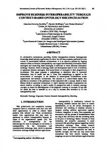
shown in Fig. 4. Tables II presents event actions. Table II - UP Event actions.
1
2
3
4 5
6
7
8
9
10
11
12
13
14
ACTIONS State = LISTEN_DIFS. Save: Time creation packet. Length packet. Fragmentation (if it is required). Know destination. Know type of packet. Buffer [AC] !=NULL. Schedule: STOP_LTN_DIFS (clock + AIFS). Schedule: STOP_TX (clock + length packet). See the TXOPLimit to send if there is any packet more. Backoff_condition=1 for STA in LISTEN_DIFS. State = TX. Schedule: STOP_RX_ACK (clock + ACK). State = LISTEN_SIFS. State = WAIT_ACK. Erase the packet. State = IDLE. Save: Increment number of packets transmitted. Delay of the transmission. State = WAIT. Increase the number of collisions. Backoff_condition = 1; Schedule: STOP_LTN_DIFS (clock + AIFS). State = LISTEN_DIFS. Refresh NAV. State = WAIT. Deschedule: STOP_LTN_D. Schedule: STOP_RX (clock + NAV). State = BACKOFF_TIMER. If (backoff_condition == 1) Generate backoff. Decrement backoff_value each time slot. Else Decrement backoff_value each time slot. Suspend backoff procedure. Refresh NAV. State = WAIT. Schedule: STOP_RX (clock + NAV). Schedule: STOP_RX (clock + RX). State = RX. Schedule: START_TX (clock + SIFS). State = LISTEN_SIFS. Schedule: STOP_TX_ACK (clock + ACK_ ength). State = TX_ACK. Save: Time creation packet. Length packet.
WCE 2007
Proceedings of the World Congress on Engineering 2007 Vol II WCE 2007, July 2 - 4, 2007, London, U.K.
15
16 17
18
19 20
21
22
23
24
25
26
Fragmentation (if it is required). Know destination. Know type of packet. Buffer [AC] !=NULL Backoff_condition = 1. State = WAIT. Schedule: STOP_TX (clock + length packet). See the TXOPLimit to send if there is any packet more. Backoff_condition=1 for STA in LISTEN_DIFS. State = TX. State = IDLE. Schedule: STOP_LTN_DIFS (clock + AIFS). State = LISTEN_DIFS. Schedule: STOP_LTN_DIFS (clock + AIFS). State = LISTEN_DIFS. State = IDLE Schedule: STOP_LTN_DIFS (clock + AIFS). State = LISTEN DIFS Schedule: STOP_RX (clock + packet_length). State = RX Schedule: STOP_RX (clock + packet_length). State = RX State = LISTEN_SIFS. Schedule: START_TX (clock + SIFS) State = TX Schedule: STOP_TX (clock + packet_length). State = RX Schedule: STOP_RX (clock + packet_length). Decrement backoff_value
The following events cause transition/change of the machine state: NEW_PCK_BK - a new packet of BK is generated NEW_PCK_BE - a new packet of BE is generated NEW_PCK_VI - a new packet of VI is generated NEW_PCK_VO - a new packet of VO is generated STOP_LTN_DIFS - end of the AIFS period for sensing the medium STOP_LTN_SIFS - end of the SIFS period for sensing the medium TIME_SLOT - the STA decrements the backoff_value START_TX- the station starts to transmit STOP_TX - end of the transmission START_RX - begin of the reception STOP_RX - end of the reception START_TX_ACK - begin of the transmission of the ACK STOP_RX_ACK - end of the transmission of the ACK ACK_OK - the ACK was received ACK_NOK - the ACK was not received START_TX_ACK - begin to transmit the ACK STOP_TX_ACK - end of the transmission of the ACK
ISBN:978-988-98671-2-6
A detailed description of the characterisation of possible states for the “machines” nodes, the simulation entities, the simulation variables, and the functions for events is given in [16]. VI. SYSTEM, SCENARIO AND ASSUMPTIONS Lets consider a cellular Wi-Fi system where each cell has a set N+1 IEEE 802.11 stations communicating through the same wireless channel. While station 0 is the Access Point or QoS Access Points (QAP), the other N wireless terminals or QoS stations (QSTA). The propagation time is assumed to be absorved by some mechanisms of the 802.11. Each station has four buffers whose size depends on the kind of service being dealt in order to guarantee a given goodput (payload of the packet). Simulations have to be undertaken in order to get the best buffer size to be used. One of the approaches is to consider the buffer with infinite size. This buffer will be filled with a MAC Service Data Unit (MSDU) generator that characterises the service being dealt in the given buffer. If the MSDU is bigger than a fragmentation threshold, it will be fragmented. In order to cope with service quality the packet transmission follows the Enhanced Distributed Channel Access (EDCA) IEEE 802.11e MAC procedure. Due to collisions or interference a packet may not be correctly received. The number of collisions is represented by a global variable that checks whether there is more than one user transmitting simultaneously. The interference issues are addressed by using a radio propagation model. The hidden terminal and the exposed terminal problem will be addressed with an appropriate level of detail. Each packet exits the buffer only after the reception of an acknowledgement, or if it has suffered more than a collision threshold. In this first phase the users are assumed to be static, and are distributed uniformly in a hexagonal area of A square meters. In this initial phase, the topology to be implemented consists of several wireless stations and an Access Point (AP). All wireless stations are located such that every station is able to detect a transmission from any other station. Three types of traffic sources where chosen, namely high priority voice, medium priority video and low priority FTP data. The traffic sources parameters are shown in Table III. In this table it are also presented the Access Categories (AC) of each type of traffic. Table III – Traffic Parameters [17].
AC Packet size Packet interval
Voice VO 1280 bit 20 ms
Video VI 10240 bit 10 ms
Background (FTP) BK 12 000 12.5 ms
We adopted the IEEE 802.11g physical layer specifications. The physical and MAC parameters are shown in Table IV.
WCE 2007
Proceedings of the World Congress on Engineering 2007 Vol II WCE 2007, July 2 - 4, 2007, London, U.K.
Fig. 4 - State transition diagram. Table IV – MAC and PHY parameters.
Slot time Physical rate ACK size SIFS RTS threshold RTS size CTS size CWmin CWmax Collisions threshold Fragmentation threshold Simulation time
VII.
0.016 ms 20 Mb/s 112 bit 0.016 ms 3000 bit 160 bit 112 bit 31 slots 1280 7 3000 100 s
SIMULATION RESULTS
Our initial simulations only considered one access point with several client machines. Results include the packet delay, throughput per second and the channel utilization. A performance measure combining throughput and delay into single function will be applied in a near future. The results for each parameter are obtained as the average of five simulations (each with different random seeds). Packet delay is the period of time between the moment at which a node becomes active (i.e., when it has data to transmit) and the moment at which the packet is successfully transmitted. ISBN:978-988-98671-2-6
The results for voice (VO), background (BK) and video (VI) are presented in Fig. 5. 40000 35000
BK
30000
VO
25000
VI
20000 15000 10000 5000 0 0
10
20
30
40
50
60
70
80
90
100
Numbe r of node s
Fig. 5 - Delay as a function of the number of nodes for BK, VO, and VI applications. From [13] the voice application, supports delays up to 30 ms, the video application supports delays up to 10000 ms and the background applications up to 500 ms. Hence, our IEEE 802.11e AP supports up to 70 voice users, 18 video users, and 20 background users with an appropriate QoS level. Another performance measure is the maximum throughput achievable for a given channel capacity. It is certain that a fraction of the channel capacity is used up in form of overhead, acknowledgments, retransmission, token delay, etc. WCE 2007
Proceedings of the World Congress on Engineering 2007 Vol II WCE 2007, July 2 - 4, 2007, London, U.K.
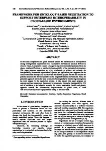
Channel capacity is the maximum possible data rate, that is, the signalling rate on the physical channel. It is also known as the data rate or transmission rate, assumed to be in our case, 20Mb/s. Throughput is the amount of “user data” that is carried by the wireless network. The results are presented in Fig. 6. The maximum achieved throughput is 14.5 Mb/s.
provide access to the medium, that ensure some degree of service, based on the channel SNR, delays, bit error rate, etc, will be tested. Handover policies between AP will also be an objective to be fulfilled. Later, our simulator will be integrated into the IT-MOTION simulator, and further work will be performed to optimise inter-working among different systems.
Throughput per sec. [Mb]i
16 14
ACKNOWLEDGMENT
BK
12
VO
10
VI
8 6 4 2 0 0
10
20
30
40
50
60
70
80
90
100
This work was partially funded by CROSSNET (Portuguese Foundation for Science and Technology POSI and POSC projects with FEDER funding), by IST-UNITE, and by “Projecto de Re-equipamento Científico" REEQ/1201/EEI/ 2005 (a Portuguese Foundation for Science and Technology project).
Number of nodes
REFERENCES Fig. 6 - Throughput as a function of the number of nodes for VO, BK, and VI applications. Channel utilization is the ratio of throughput to channel capacity. It is independent of the medium access control. It is obvious that one is the ideal situation. The results are presented in Fig. 7. The maximum found is 0.7. VIII. CONCLUSIONS AND FUTURE WORK Our simulator still requires extra validation but the results already obtained are near of the ones in the bibliography [17]. In future work the implementation of BlockACK and of the physical layer procedures will be addressed. During this development, several difficulties were found, like misleading information found in the standard. 0.8 0.7
BK
0.6
VO
0.5
VI
0.4 0.3 0.2 0.1 0.0 0
20
40
60
80
100
Num be r o f no de s
Fig. 7 - Channel utilization, as a function of the number of nodes, for VO, BK, and VI applications. It was hard and still not very clear to understand how the TXOP work. At this point, the implementation of the BlockACK has several hypotheses for assumptions that point to several paths regarding the implementation. Higher throughputs are found for the FTP service and for the video service, mainly because the frames transmitted in these services are longer than the ones for the voice application. However, the number of supported users is higher for voice. This simulator will be a tool that will allow for tuning-up several parameters like the ones related to how to use BlockACK, normal ACK, and NO ACK policies. Policies that
ISBN:978-988-98671-2-6
[1] D. T. Phan Huy, V. Monteiro, A. Gameiro, X. Yang, J. Rodriguez, R.Tafazolli, System level performance evaluation of MATRICE air interface, 13th IST Mobile & Wireless Communications Summit 2004, 27-30 June, Lyon, France [2] J. Antoniou et al, “Designing a System Level simulator for E-UMTS”, http://seacorn.ptinovacao.pt/workshop/WORKSHOP/Papers%20Workshop/ Workshop_WP4_SLS_Design.pdf [3] S Haemaelaeinen, H Holma, K Sipilae , “Advanced WCDMA radio network simulator”, Proceedings of the IEEE International Symposium on Personal, Indoor and Mobile Radio Conference (PIMRC´99). Osaka, Japan, September 1999, pages 951-955. [4] Ghorashi, S.A. Homayounvala, E. Said, F. Aghvami, A.H., “Dynamic simulator for studying WCDMA based hierarchical cell structures”, 12th IEEE International Symposium on Personal, Indoor and Mobile Radio Communications, pp. D-32-D-37, vol.1, 2001. [5] J. Rodriguez, V. Monteiro, A. Gameiro, R. Legouable, N. Ibrahim, and M. Shateri, “4 MORE System Level Performance”, 6th International Telecommunications Symposium (ITS2006), September 3-6, 2006, Fortaleza-CE, Brazil. [6] The EVEREST project, http://www.everest-ist.upc.es/ [7] The ROMANTIK project, http://www.ist-romantik.org/index.swf [8] The ARROWS project, http://www.arrows-ist.upc.es/ [9] A. Doufexi, E. Tameh, A. Nix, S. Armour, A. Molina, “Hotspot wireless LANs to enhance the performance of 3G and beyond cellular networks,” IEEE Communications Magazine, pp. 58-65, July 2003. [10] Jijun Luo Mukerjee, R. Dillinger, M. Mohyeldin, E. Schulz, E., “Investigation of radio resource scheduling in WLANs coupled with 3G cellular network”, IEEE Communications Magazine, pp. 108-115, June 2003. [11] V. Monteiro, J.Rodriguez, and A. Gameiro , “Weighted Priority Scheduling for Beyond 3G Systems based on MCCDMA”, European Wireless, Athens, April 2-5th , 2006. [12] A.Nascimento, J.Rodriguez, A.Gameiro, “Utility Based Scheduling for Wireless Systems”, 15th IST Mobile and Wireless Communications Summit, Myconos, 4 -8th June 2006. [13] Nuno Anastácio, Francisco Merca, Orlando Cabral, Fernando J. Velez, “QoS Metrics for Cross-Layer Design and Network Planning for B3G Systems,” in Proc. of IEEE ISWCS2006 - Third International Symposium on Wireless Communication Systems, Valencia, Spain, Sep. 2006. [14] IEEE Std. 802.11e; Wireless LAN Media Access Control (MAC) and Physical Layer (PHY) Specifications, 2005. [15] IEEE Std. 802.11; Wireless LAN Media Access Control (MAC) and Physical Layer (PHY) Specifications, 1999. [16] Jonathan Rodriguez (editor), “Intermediate Specification of Algorithms for Cross-Layer Optimisation,” IST UNITE CEC deliverable 4-026906/IT/DS/4.1.1, IST Central Office, Brussels, Belgium, 2007. [17] Quiang Ni, “Performance Analysis and enhancements for IEEE 802.11e Wireless Networks,” IEEE Network, July/August 2005, pp. 21-27.
WCE 2007