AIAA 2014-0041 AIAA SciTech 13-17 January 2014, National Harbor, Maryland 52nd Aerospace Sciences Meeting
Simulation of Rotor in Hover: Current State and Challenges Nathan Hariharan
HPCMP CREATE-AV, Lorton, VA (
[email protected])
Alan Egolf
Sikorsky Aircraft Corporation, Stratford, CT
Lakshmi Sankar
Georgia Institute of Technology, Atlanta, GA
Downloaded by GEORGIA INST OF TECHNOLOGY on June 26, 2014 | http://arc.aiaa.org | DOI: 10.2514/6.2014-0041
Abstract A helicopter is subjected to a wide variety of flight conditions with disparate objectives; these include efficient cruise and hover, and high-performance maneuvering. The hover condition remains a very important design consideration because it represents the true value of the helicopter, and it is a limiting design point in terms of power requirements. Accurate numerical prediction of rotor-blade aerodynamic parameters such as thrust, torque and efficiency requires an accurate modeling of the vortex wake. Despite tremendous advancements in the ability to preserve the tip vortex from first principles, the capability to consistently and reliably predict performance parameters for a new rotor-blade has still been elusive. These challenges provide the motivation for the AIAA Applied Aerodynamics Technical Committee Rotorcraft Simulation Working Group’s efforts to evaluate hover simulation capabilities across government organizations, industry and academia. The AIAA Applied Aerodynamics Rotor Simulation Working Group aims to bring together government, industry and academic participants to evaluate and further rotor-in-hover performance predictions. The invited session at SciTech 2014 is the first step to assess different approaches for the prediction of baseline S-76 rotor planform. Future plans include a full workshop at SciTech 2015 to evaluate prediction of performance for S-76 planforms with various tip-shapes. 1. Motivation A helicopter is subjected to a wide variety of flight conditions with disparate objectives; these include efficient cruise and hover, and high-performance maneuvering. Next generation aircraft are increasingly required to improve performance in all areas. Achievement of significant advances in rotorcraft capability requires advanced concepts such as complex rotor tip shapes and active rotor control. The hover condition remains a very important design consideration because it represents the true value of the helicopter, and it is a limiting design point in terms of power requirements. The flow field around a rotor, whether in forward flight or hover, is difficult to model due to the presence of strong vorticity. The flow phenomena for a rotor differ from that for a wing in forward flight, because of the differing influence of their respective wakes. For a wing in forward flight, the generated tip vortex and the vortex sheet are quickly convected away from the wing, and the influence of the shed wake on the flow field in the vicinity of the wing is small. For an adequate numerical simulation of a wing in forward flight, it is sufficient to capture the generated tip vortex in the vicinity of the wing.
In contrast, in the flow field around a rotor, the strong vortex wake system lingers in the vicinity of the rotor. In hover, the strong tip vortex coils beneath the rotor, and significantly alters the effective angle of attack seen by the rotor. The schematic in figure 1 shows a sketch extracted from a smoke study of a model rotor in hover [1]. Accurate numerical prediction of aerodynamic parameters such as thrust coefficient and induced torque coefficient therefore require an accurate modeling of the structure, strength and trajectory of the tip vortex. In hover, the tipvortex forms a helical vortex system beneath the rotor that can persist as discrete vortices below the rotor for several rotor revolutions. The first vortex passage significantly alters the effective angle of attack distribution of the rotor blade, and thus the rotor efficiency. The core size of the tip vortex is typically one-tenth of the rotor-blade chord length, and in order to accurately capture the entire tip vortex system without dissipation, it requires a large amount of computing power and sophisticated numerical methods. For instance, a traditional second-order NavierStokes code requires ~100 million grid points to resolve 3-4 revolutions of the vortex system. Further, the inviscid helical wake vortex systems based on vortex lattice methods have been shown to be neutrally stable, and experimentally observed wake systems indicate that the tip vortex structures become unstable after above 4 blade
passage intervals, hence accurately predicting a stable position of the tip vortex relative to the blade is a difficult challenge.
Downloaded by GEORGIA INST OF TECHNOLOGY on June 26, 2014 | http://arc.aiaa.org | DOI: 10.2514/6.2014-0041
The underlying issue in modeling these flows is the necessity to properly account for the complex vortex system generated by the rotor. Researchers in the past two decades have adopted a broad class of methodologies with various levels of complexity to model the vortex system. This paper first briefly reviews the historical progress of first-principles based rotor hover predictions. This is followed by typical results from two, three and four-bladed hover simulations using current state-of-the-art methods, their strengths and weaknesses in predictive hover capabilities. The last section discusses the AIAA Applied Aerodynamics Rotorcraft Simulation Working Group and its efforts for standardized hover evaluations, in particular the scope and details of the invited hover simulation session at SciTech 2014. 2. Review of First-Principles Rotorcraft Flowfield Simulation Methodologies for Hover Several excellent survey articles that summarize rotorcraft flow simulation efforts are available in literature: McCroskey[2], Srinivasan and Sankar[3], Landgrebe[4], Hariharan and Sankar[5], Strawn and Caradonna[6]. The present work is not intended to be an all-inclusive survey of rotorcraft wake modeling. In this paper, we briefly review efforts at modeling rotor-wake in hover, with the emphasis on Navier-Stokes based “first-principles” wake capturing. The earliest methods for modeling rotors were based on an extension of Prandtl’s lifting line theory for wings. In these techniques, the individual blades were modeled as “lifting line” vortices, and the wake was modeled as a deformed helix. During the 1970’s, Gray[1], Landgrebe[7], and others developed a prescribed wake model to define this helical geometry. Their models were based on experimental observations, such as smoke visualization of the wake. Kocurek and Tangler[8] and Shenoy[9] refined the lifting line method by using a lifting surface representation of the rotor with an improved prescribed tip vortex and inner vortex geometry. Several vortex wake approximations have been made for forward flight. Coleman et al.[10] and Lewis[11] use vortex rings or vortex tubes to obtain the induced velocity from the approximation of the trailed wake vorticity. Later, Egolf and Landgrebe[12] and Beddoes[13] developed different prescribed wake models based on the different prescription of the vertical displacement of the tip vortices. The prescribed wake technique is simple and
effective but its applicability is limited to rotors having geometry similar to those used in experiments. The lifting line methods require a table look up of airfoil load data, and modeled the unsteady blade wake interactions in a quasi-steady manner. Free wake analysis methods were subsequently developed by Landgrebe[14],[15], Clark and Leiper[16], Sadler[17],[18], Scully[19], Summa[20],[21], Bliss and Miller[22] and others. In these methods the tip vortex was modeled as a series of line vortex filaments and was tracked using a Lagrangian technique. These free wake methods accounted for self induced distortions of a rotor wake in forward flight such as roll up. The velocity field was computed using the Biot-Savart law and numerical integration techniques. Johnson[23] used the free wake technique as an option in his computer program CAMRAD (Comprehensive Analytical Model of Rotorcraft Aerodynamics and Dynamics). This program is widely used even to this date to compute inflow velocities, airloads, and rotorcraft performance, stability and control. Caradonna and Isom[24] extended the transonic small disturbance theory which became available during the early 1970’s to transonic flow over rotors. This methodology allowed a first principles based study of forward flight conditions and tip effects. In this approach, the effect of the vortex wake was modeled as a table of angle of attack changes, computed from a comprehensive analysis case such as CAMRAD. During early 1980’s, Chang[25] modified the full potential flow solver FL022 for isolated wings to model rotors. Egolf and Sparks[26] modified Chang’s work by embedding the vortex element associated with the tip vortex with the potential flow field. Their approaches solved either the steady or quasi-steady form of the potential flow equation. Sankar and Prichard[27], Sankar et al.[28], Strawn[29], Bridgeman et a1.[30], Strawn and Caradonna[31] developed unsteady full potential flow based rotor solvers. In all these applications the rotor wake effects ere computed either using a prescribed wake model or a free wake model such as CAMRAD. The full potential solvers could analyze transonic flow with mild shocks, though in an isentropic manner. Viscous effects were accounted only through a boundary layer correction. Ramachandran et al.[32],[33] solved the full potential equation and included the rotor wake effects using a Lagrangian based approach for tracking the vortex filaments. During late 1980’s, Euler methods matured to a point where calculation of the rotor flowtield in hover and forward flight was feasible. These methods solved the mass, momentum and energy conservation equations in a time dependent fashion using finite-difference or finite-
Downloaded by GEORGIA INST OF TECHNOLOGY on June 26, 2014 | http://arc.aiaa.org | DOI: 10.2514/6.2014-0041
volume methods. These solvers did not include viscous effects but could analyze the transonic flow with nonisentropic shocks. Sankar et al.[34], Agarwal and Deese[35], and Hassan et al. [36] developed Euler solvers for isolated rotors. Again, the wake effects were modeled as an inflow angle of attack table supplied from a separate comprehensive analysis. Wake and Sankar[37] were one of the first few researchers to develop a Navier-Stokes code to analyze rotor flow fields in hover and forward flight[38]. They used a C-H computational grid and a hybrid ADI implicit time marching algorithm. These solvers were computationally expensive, but had all the features required for modeling the advancing blade transonic flow and the retreating blade dynamic stall phenomena. The only drawback of these codes was that they were dependent on external wake models for calculation of inflow velocities. Smith and Sankar[39] and Tsung et a1.[40] extended this NavierStokes code to include the aeroelastic effects and improved the spatial accuracy from second to fourth order using a compact operator implicit scheme. Narramore et a1.[41] used Navier-Stokes methods to investigate viscous phenomena over rotors-blades such as flow separation and dynamic stall. Chen, McCroskey and Obayashi[42] used an implicit L-U factorization scheme and an external free wake model to solve forward flight rotor flows. Mello[43], Berezin[44] and Moulton et al.[45] have developed hybrid Navier-Stokes/Full Potential Equation based solvers in an effort to reduce the computation time. Here, the computational domain is divided in to an inner domain comprising of the body and the near wake and an outer domain far from the body. Navier-Stokes equations are solved in the inner domain and the full potential equation is solved in the outer domain where viscous effects are negligible. They were successful in reducing the computation time by 50% when compared to the full Navier-Stokes computation times. Mello[43] also developed a non-reflective interface boundary condition procedure to eliminate the false acoustic reflections at the Navier-Stokes/Full potential interface boundary. More recently, Moulton et al.[46], Berkman and Sankar et a1.[47] have used overset grids for the Navier-Stokes and Potential free wake solutions. During the early 1990’s, taking advantage of the enormous improvement in computing capabilities during the 1980’s, a new class of Euler/Navier-Stokes codes were developed in an effort to capture the rotor wake from first principles without any need for external wake models. Removing the need for external information that depends on rotor geometry is a big step in the true simulation of the rotor flowfield. These first principles based solvers are
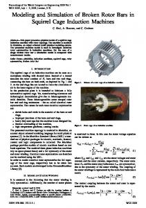
particularly useful in analyzing new or complex rotor blades where no experimental data available. Strawn and Barth[48], Srinivasan and McCroskey[49], Srinivasan et a1.[50], Srinivasan and Baeder[51], Srinivasan et a1.[52], Duque[53], and Duque and Srinivasan[54] solved the hovering rotor flowfields by capturing the rotor wake in an Eulerian fashion, and from first principles. Hariharan and Sankar[55] used high order methods to solve the flow field of rotor in hover from first principles. Figure 2 shows a typical grid configuration used in these studies – they employed cylindrical grids over a single blade and employing periodic boundary conditions to replicate the presence of the other blades. The tip vortices in most of the analyses were captured up to one revolution, beyond which the vortex is diffuse due to numerical dissipation. In an effort to reduce the numerical dissipation, Steinhoff et a1.[56], Wang et a1.[57] used vorticity confinement techniques to prevent the tip vortex diffusion. An important development in the development of the firstprinciples scheme was the use of higher order methods to capture the rotor wake. Hariharan et al. [58, 59] introduced the idea of using higher-order, low dissipation WENO based numerical methods to capture the wake effectively. Several researchers have since explored different higher order methods (References [62], [63], [64], [65]). Figure 3 shows the benefits of using a fifth-order spatially accurate scheme versus a third order scheme to capture the tip vortex off a NACA0015 wing (from Reference [58]). Even though high order methods provided efficiency in convecting the vortex system with minimal grid requirements (typically 5-12 points across the core depending on the scheme), one still required the minimal grid requirement in the path of the vortices. Developments in providing grid points where they matter first came in the form of overset grid methods. Overset grids were first introduced to study rotorcraft interactional problems. McCroskey[64] had made the suggestion, and several researchers (References [66], [67], [68], [69], [70], [71]) used the idea to compute rotor-airframe computations. Overset grid methods were also then used as a mechanism to provide Cartesian “wake” grids for hover computations. Figure 4 shows the use of Cartesian single-block structured wake grids –in conjunction with high order scheme- to capture the vortex system of a two-bladed rotor in hover (from Reference [61]). The tip vortex was captured much further down when compared to earlier efforts, i.e., as shown in figure 3. The next ingredient employed in order to provide grid points in the path of the wake vortex structures was the use of adaptive mesh refinement (AMR). AMR involves
Downloaded by GEORGIA INST OF TECHNOLOGY on June 26, 2014 | http://arc.aiaa.org | DOI: 10.2514/6.2014-0041
automatically refining and coarsening the grid locally to resolve important flow features. By focusing memory usage and computational effort in these localized regions, a highly resolved solution may be obtained much more efficiently than a globally refined grid of equal resolution. Strawn and Barth[72] first demonstrated the concept using AMR in an unstructured Euler solver. Potsdam[73] applied unstructured AMR to wind turbine wake predictions. Deitz et al. [74] introduced an overset-grid based approach that moved tubular curvilinear grids to align with the tip vortices. Hariharan [60] used Cartesian overset vortexgrids to analyze tip vortex from wings. Figure 5 shows (from Reference [60]) the use of self-adaptive structured overset vortex grids –in conjunction with seventh order accurate WENO scheme to capture wing-tip vortex without any noticeable dissipation over large distances. However, the extension of a single vortex tracking grid proved geometrically difficult to implement robustly for rotor in hover. Vasilescu et al. [75] used structured adaptive redistribution to study rotor in hover. Meakin[76] proposed a Cartesian-based AMR scheme within the Overflow[77] code. This approach was recently extended by Holst and Pulliam[78,79]. The aforementioned efforts all adopted AMR techniques targeting steady-state solutions; a solution is computed on an initial mesh, the mesh is reconstructed to adapt to features in the solution, then the simulation is run again on the new mesh. This steady-AMR approach is useful for isolated rotors in hover conditions, but many of the more complex problems in rotorcraft require time-dependent moving body capabilities. An AMR scheme that can resolve unsteady effects like rotor-fuselage interactions or rotor vehicles in forward flight or maneuver conditions requires an unsteady-AMR approach, for which the grid is adapted continually in a time dependent manner throughout the simulation. An unsteady, time-dependent off-body Cartesian grid generation and framework is the SAMRAI [80] Cartesian grid infrastructure. The SAMRAI[81] infrastructure supports the ability automatically to perform Cartesian refinement and adapt to geometric and flow features, and is scalable across multiple distributed processors. Helios is a new computational platform under the CREATEAV umbrella targeted towards rotorcraft aero-mechanics simulations. Details of the underlying platform design, validation cases, and targeted applications can be found in Reference [82]. At the heart of the Helios platform is an innovative dual-mesh paradigm with an unstructured mesh solution in the near-body, and Cartesian meshes in the offbody and using automated overset information exchange as a means of communication. The unstructured near-body solver facilitates ease of grid generation for complex body
shapes, and the solution is computed using the secondorder accurate flow solver NSU3D [83]. The off-body Cartesian grid generation is automatically constructed using SAMRAI [80]. Cartesian grid infrastructure, and employs an efficient fifth-order spatially accurate Euler solver, SAMARC [81]. The Helios platform deploys overset hole cutting using an implicit methodology [82] that does not require any user interference. The overset connectivity is handled by PUNDIT [82], and the entire process supports parallel/distributed computation. Figure 6 illustrates the various components of the Helios platform. Figure 7 shows sample off-body Cartesian adaptive tracking of the tip vortex from a NACA0015 wing swept off at a yaw angle. Instead of a single vortex grid that reshapes to the vortex (i.e., figure 5), in this methodology several smaller, overset, isotropic Cartesian grids track the vortex. The automated process makes it tenable to capture complicated wake vortical patterns occurring in a rotor flowfield environment. 3. Hover Capabilities and Needs from Recent Simulations Results from Recent Hover Simulations: Capabilities and Needs In this section, we present some sample results from using Helios for three different rotor blades in hover: (i) Twobladed Caradonna-Tung rotor blade [88], (ii) Three-bladed TRAM rotor [89], and (iii) Four-bladed UH60A model rotor in hover [90]. Based on the results, discussions on current state of the capabilities, and shortcomings are explored. 3.1 Two Bladed Caradonna-Tung Rotor: The Caradonna-Tung [88] rotor-blade - a two bladed rotor model tested in 1981- was used to explore several aspects of predicting hover behavior using Helios. The blade planform consists of untwisted, non-tapered NACA0012 sections with an aspect ratio of 6. An unstructured blade grid was generated using the AFLR3 volume grid generator. The background Cartesian grid finest-level resolution was set at 18-grid-cells per chord (from Reference [91]). The off-body Cartesian grid count was 22.5 million. Figure 8(a) shows vorticity magnitude contours, and vorticity isosurfaces (colored by z-velocity) with the computational order of accuracy in the Cartesian grid being retained at the second-order level (for a collective pitch of 8 degrees). The wake system evolves below the vortex further down before being consumed by the ring-vortex. Figure 8b shows wake vorticity contours when the computational order of accuracy of the Cartesian grid was th increased to 5 . The wake vortex system is sharply defined with the vortex-ring structure pushed further down, but persisting in the eventual converged solution. Figure 9(a)
Downloaded by GEORGIA INST OF TECHNOLOGY on June 26, 2014 | http://arc.aiaa.org | DOI: 10.2514/6.2014-0041
shows vorticity iso-surfaces of both the computed tipvortex, and the wake-sheet systems with the off-body solution computed further down. Figure 9(b) shows the well-known idealized schematic of a rotor-wake in comparison. The agreement between figures 9(a) and 9(b) is striking. The near-body unstructured grid was refined further (see Reference [91] for details) to ensure that the computed thrust coefficient matched the experimental value [88]. The off-body Cartesian far-field boundaries were pushed further out to convect the toroidal ring-vortex down. Figure 10a shows iso-vortex contours of the wake for the modified simulation. Figure 10b shows the vorticity contours for a similar setting, but now employing AMR to track the tip vortex rather than fixed refinement. The tracking was based upon vorticity, and seems to capture fine wake features. The computed thrust values did not change between the non-AMR and AMR solutions. As the AMR solution was computed beneath the rotor, secondary vortex structures began appearing, when the pitch of the structure (distance between two successive helical vortex strands) became smaller in the far-wake. Figure 10a shows iso-vorticity contours when the wake vortex structure is tracked using AMR beyond the initial helical pattern to the vortical ring patterns at the bottom. As multiple strands of tip-vortex structures close-in on each other cross-wise hair-pin vortices appear along wrinkles along the main-vortex structures. Figure 10b takes a closer look at these vortices, and they appear as alternating pairs of +ve/-ve vortices corresponding to successive “wrinkle” in the main-vortex structure. For this two-bladed wake system, even if the solution is run much further, these secondary vortex instabilities are confined to the bottom part of the wake, and do not influence the integrated loads. The issue of the secondary vortex instability is explored further in the study of UH60A rotor in hover. 3.2 V22 TRAM Rotor in Hover The Tilt Rotor Acoustic Model (TRAM) is a quarter-scale model of the Bell/Boeing V-22 Osprey tiltrotor aircraft[89]. Isolated rotor experimental measurements were taken from the open jet section of the Duits-Nederlandse Wind Tunnel (DNW). A full-span dual rotor model was tested in the 40x80 test section of the National Full-scale Aerodynamic Complex (NFAC) at NASA Ames in 2000. Further details of the TRAM tests are available in Reference [89].
Analysis is presented for a range of near- and off-body meshes. All cases use a Mtip of 0.625. Four near-body grids were chosen - coarse, med, fine, and the fine mesh with local refinement added in the vicinity of the tip and first tip vortex (referred to as “fine-a”). The grid sizes are 1.8M, 2.8M, 8.3M, and 9.4M nodes for the coarse, medium, fine, and fine-a grids, respectively (figure 12a). The computed vorticity iso-surface is shown on the right for comparison. Note that tip vortices in the near-body are better captured by the finer meshes, particularly with local refinement. The off-body grid extent, and refinement at different levels is shown in figure 12b (finest grid, Level-8 off-body grid at 5% tip chord) Table-1 summarizes the number of iterations, computation time, and computed figure of merit when running Helios with different near and off-body mesh combinations. The reported number of iterations is the number required to converge rotor forces - thrust, torque, and figure of merit. The convergence was set to < 0.1% variation in figure of merit, although some cases showed oscillatory behavior with variation up to 0.3%. Note the FM is mostly converged after 15,000 iterations but exhibits force oscillations that become periodic after about 20,000 iterations. The periodic variation is +/-0.2% of the reported converged value. The observed variation in each case is given in Table-1 Two important conclusions can be drawn from these results. First, appropriate resolution is needed in both the near-body (NB) and off-body(OB) meshes to accurately compute figure of merit. Increasing one without the other has limited effect. Consider the results with the medium NB mesh; using a 5 level OB grid the FM is off by more than 10%; with a 6 level OB grid the error reduces to about 4%; the error remains about the same with the 7 level OB grid. Hence, the OB grid should be refined to be commensurate with the NB grid, but further resolution does not improve the force calculation. Improved resolution of the near-body is required to further enhance the FM computed result. The second important conclusion is that very accurate FM predictions can be obtained with fine meshes in Helios. Computations with the “fine” and “fine-a” near body meshes coupled with the 7 level offbody grid are within 0.4% of the measured data, with a 0.2% periodic variation. AMR was turned on using the fixed solution as a starting point, adding more levels. For instance, an 8Level-AMR case was started from a converged 7-Level-fixed result. It was that use of AMR is effective at resolving the wake, but has limited impact on the airloads results.
Downloaded by GEORGIA INST OF TECHNOLOGY on June 26, 2014 | http://arc.aiaa.org | DOI: 10.2514/6.2014-0041
Figure 13 shows a comparison of the computed wake using fully unstructured without AMR (13a) compared to the dual-mesh calculation in Helios with “med” (13b) and “fine-a” (13c) near-body meshes, both with 8L-AMR offbody grids. Clearly, the wake resolution is improved significantly with the use of Cartesian-based AMR and local refinement in the near-body. Figure 14 shows vorticity isosurfaces in the wake for the AMR simulation. Figure 15 compares the predicted performance characteristics of the TRAM rotor against experiments, and good agreement is found. Secondary braid instability does not feature dominantly for the TRAM case.
3.4 UH60 Rotor in Hover The UH60 model rotor in hover tested by Lorber [90] has been one of the benchmarks for testing any rotor-code, i.e. as in References 49-52. A UH60A model-scale rotor was set up in hover conditions. The grid is based on the fine UH60A forward flight model developed previously (Sankaran [92]) with the following modifications: 1) Aeroelastic deflections (section twist and coning), based on experimental measurements at a nominal CT/ (0.085), were included using the CFD/CSD prescribed motion capability. A static, deflected mesh was generated from the deflected geometry and reused as input to the grid preprocessing process. 2) Near-body grid clustering around the tip vortex and expected location of the returning tip vortex (first blade passage) was included. 3) The trim tab was removed. 4) A notional center-body has been included to prevent upflow recirculation. The near-body mesh had 16.8 million points after being trimmed and is shown in figures 16 and 17. Calculations were performed using the non-inertial formulation for off-body grid densities of 10% (2.0 in., Level-8) and 5% (1.0 in., Level-9) chord. A large outer boundary of 20R was used in conjunction with Dirichlet outer boundary conditions. Fixed refinement and AMR were used for both mesh levels. Fixed refinement Level-8 vorticity iso-surfaces are shown in Figure 18. The tip vortex appears to be overly diffused given what would normally be considered reasonable grid density (10% chord spacing). The large core sizes promote premature interaction and merging of adjacent vortices after less than 1 rotor revolution. Due to the large core size, the returning vortex is intersected by the blade, as seen in figure 19 – which is incorrect. AMR –with the same L8 level of refinement - is seen to reasonably capture the
discrete vortices, but the wake sheets are not resolved (figure 20), and the first-passage vortex still impinges on the following blade. Significant unsteadiness in the flow field due to the merged vortices do not results in converged thrust and figure of merit values. The computed figure of merit was considerably low at 0.68 compared to a measured (Reference [90]) value of 0.734 (for thrust condition (CT = .007, Collective Pitch = 10.5 deg). In order to improve the wake resolution, the L9 (5% chord) grid was simulated using both fixed refinement and AMR. Using the fixed L9 refinement the initial computation –at 10,000 steps- predicted the first-passage wake position better –no impingement on the following blade- as shown in figure 21. Secondary rotor-axial braided vortex instabilities begin appearing in the lower parts of the wake, as in the Caradonna-Tung rotor computations. However, in the UH60 simulation, as the computation was run further -14,000 iterations, figure 22 - the secondary vortex braid instability began appearing even in the near wake, and starts the break-up of the entire helical wake structure. This is dramatically shown in figure 23(i)a-g where off-body sub-stepping was been turned off (as opposed to previous solutions). Note that there are instabilities associated with the starting vortex (Figures 23(i)ab) but these are removed from the solution as the calculation progresses (Figure 23(i)c). Further simulation shows that the secondary instability braids eventually return en masse (Figures 23(i)d-h). Dissipation level (higher and lower) and lower CFL values also produced similar results. The inertial formulation shows similar issues, which is not surprising given that the Helios explicit offbody Runge-Kutta scheme is essentially time-accurate, with the non-inertial formulation merely including the addition of a rotational source term. In order to explore the effect of off-body damping on the computed wake, calculations were performed in Helios with off-body dissipation values of 0.1, 0.25, and 0.50 (default). Figure 23(ii)a-c compares the L9 fixed refinement wake for three different dissipation values at the same time step (10,000). Lower dissipation has the expected effect of sharpening the shear layer and tip vortices. However, at the same point in time the braid instabilities are promoted. Figure of Merit results from the L9 grids are also unstable and under-predict the measured value, similar to the L8 grid. In summary, while this work is ongoing, some general conclusions can be drawn from the investigations so far: 1.
Lower dissipation improves the wake shear layer, but promotes the formation of off-body braids.
Downloaded by GEORGIA INST OF TECHNOLOGY on June 26, 2014 | http://arc.aiaa.org | DOI: 10.2514/6.2014-0041
2.
Lower values of off-body CFL do not improve offbody stability or affect the generation of braids.
3.
Off-body viscous terms and turbulence models are required to more fully investigate off-body flow features.
Clearly this remains an open topic and requires considerably more work to understand these unresolved issues. Until the secondary vortex instability and their associated unsteadiness and instability are resolved, wellconverged hover calculations for planforms such as the UH60-A are difficult to obtain, and their accuracy is in doubt.
3.5 Secondary Vortex Braid Instability Hover Simulations The appearance of secondary vortex braid instability is seen in all the well-resolved hover solutions considered in this paper (3.2 Caradonna-Tung rotor, 3.3 TRAM rotor, 3.4 UH60A rotor). It also appears in forward flight cases and maneuvering cases, but the since the overall vortex system is stabilized by an external (non-self-induced by the vortex system as in hover) flow, the presence of secondary braids do not affect the overall computation. Even within the three rotors considered, -from a practical standpoint – the appearance of the braids prevents meaningful load and figure of merit predictions only for the UH60A rotor blade. In order to understand the underlying braid structure better a closer look at the UH60A flowfield was warranted. Figure 24 takes a closer look at the vorticity iso-surfaces around the braids bridging successive helical-vortex strands of the main-wake. The alternating +ve/-ve braids hooking around the main-helical strands –transferring energy from the large scale to small scale- is classic mixing mechanism in shear-layers. Figure 25 reproduces the picture of LES –employing Smagorinski sub-scale model - simulations from evolving spatial shearlayers (Comte et al. [93]). The axial braids seen bridging the primary spanwise oriented shear-layer roll-up structures are a well known phenomena. Thus given the numerical foundations of what is being solved, the appearance of the instability braids between closely convecting vortical strands is correct. However, the appearance of braids which completely overwhelms the stability of the main-helical-wake structure as in the UH60A computation is physically incorrect. There is a lack of experimental evidence of these structures as the primary vortex breakdown mechanism in the literature. Whereas vortex-pairing and unsteady jitter of the entire helical wake patterns have been experimentally observed
(Komerath et al. [94, 95,96], Mula et al. [97]) in literature, i.e., as in figure 26 [from Reference 96] - wholesale breakdown of the helical vortex structure is not supported. The secondary braid vortex instability of wake encountered in Helios has also been reported in OVERFLOW (Chaderjian et al. [98]) hover simulations, particularly with the use of higher-order schemes and increased off-body grid resolution. Figure 27 shows the vortex breakdown from Reference [98] - employing a SADES model in the off-body with spacing as fine as 2.5% chord for a V-22 (TRAM) tilt-rotor in hover. As observed in the earlier paragraph, we do not believe they are completely physical, but are manifestation of numerical instability. If they are physical, they are certainly exacerbated by the numerics, such that in reality their appearance is significantly reduced or act as a mechanism to break down the vortical structures far from the rotor plane. It is interesting that in spite of huge strides made in the ability to capture wake structures without dissipation over the last 15 years, one of the best reported loads, and figure of merit for the UH60A model rotor, still remains the cylindrical structured grid simulation by Srinivasan et al.[49] (see figure 28). It is also instructive that firstprinciples rotor-hover simulations over the years employing structured cylindrical stretched grid ( i.e., Srinivasan et al.[49], Hariharan et al.[55], Vasilescu et al. [75]) –figure 29-, and stretched Cartesian grids(i.e., Hariharan and Wake[101]) –figure 30- never reported such braid instabilities. Several factors were common to these simulations: (i) Cylindrical grids with periodic boundary conditions (ii) Grid stretching in the downward convection direction (no abrupt grid density changes) (iii) Mostly use ENO/WENO/STVD high order numerical schemes Most of the above-mentioned simulations do not quite resolve the wake structure (tip vortex-strength, and coresize), and hence are possibly too damped to exhibit braid th instability. However, in the 7 order WENO simulation of the UH60A rotor wake by Hariharan and Wake [101] – figure 30b- using stretched Cartesian grids, the tip vortex core size in the near-wake was ~0.2c, comparable to the current crop of high-fidelity Helios and Overflow simulations. The wake reported in [101] indeed exhibits unstable behavior and vortex-pairing as seen in figure 29a. However, no pathological cross-wise braid instability
breakdown was seen. Why would grid stretching in the downwash direction possibly avoid braid instabilities? Some possible reasons:
Downloaded by GEORGIA INST OF TECHNOLOGY on June 26, 2014 | http://arc.aiaa.org | DOI: 10.2514/6.2014-0041
1. Grid stretching acts as a natural damping mechanism to fade out far-wake without bouncing back (similar to coarse-grid damping employed for acoustic computations) 2. Grid stretching potentially provides faster computed vortex-system self-convective velocities (see Reference [102]). This avoids farwake slow-down without the appropriate damping mechanism to go with it. 3. Grid stretching avoids abrupt grid density changes acting as a wave-reflection mechanism. We have speculated on possible directions first-principles simulations could to take in order to become routine predictive tools for rotor in hover. Further research is required to address the braid instability problem, both at a fundamental physics level of vortex system degeneration and at a modeling level of vortex system capturing, to be consistently able to predict hover performance for all class of rotor-blade planforms. 4. AIAA APA TC Standardized Evaluation of Rotor in Hover Simulation The AIAA Applied Aerodynamics Technical Committee put together a Rotorcraft Simulation Working Group [103] comprising of members across DoD, NASA, Industry and Academia with the immediate purpose of: 1. Assess current state-of-the-art government agencies and academia.
across
industry,
2. Scope critical challenges in consistently, and accurately predicting hover and forward flight. 3. Act as leading catalyst in the development of computational methods for solving rotorcraft problems. One of the first decisions of the working group was to define the scope of the group. It was quickly felt that between the UH60 Airloads Workshop, and AHS forum focus most of the forward flight simulation issues are being addressed and hence the APA’s Rotor Simulation WG focus should not be on forward flight simulations. The main focus of the APA Rotorcraft Simulation WG was to be on hover simulation and prediction. In as much there have been a number of first-principles simulations in literature reporting good agreement on
hover performance and figure of merit, often incorrect surface lift predictions integrate out to produce reasonable overall results. The holy grail of accuracy of hover simulations need accurate predictions along three fronts: (i) Integrated performance numbers (ii) Radial surface pressure distributions, (iii) Correct location of the tipvortex system, especially the first-passage.There were several challenges in setting up a common rotor-in-hover test case to enable a workshop and get different participants to predict hover performance using their codes: • Obtaining a realistic geometry that has force balance, surface pressure tap, and PIV data to validate. • Public availability of rotor-blade geometries. Most realistic geometries are company-owned and are unlikely to be allowed unrestricted distribution. • Complications deformations.
due
Several candidate existing discussed for merits:
to
blade
benchmark
•
UH60A model rotor
•
HART
•
Comanche
•
S-76
aeroelastic cases
were
The Working Group arrived at several decisions on the scope and nature of the initial standardized hover evaluations: • It was felt that a comparative trending study between rotor-blade planforms with varying tip shapes using different simulation codes will be a very useful exercise in understanding the capabilities and gaps of current generation of codes. • For initiating the standardized evaluation, the ability to predict aeroelastic deformation was not part of the evaluation – we need a better understanding of our ability to predict hover before the complexities of prediction aeroelastic deformation are included. After reviewing the available data noted above and the issues with each, it was concluded by the working group that the S-76 rotor data would be best for quickly getting standardized evaluations off the ground [104,105]. It is recognized that this rotor data does not have measurements of the highly desired spanwise airloads and
Downloaded by GEORGIA INST OF TECHNOLOGY on June 26, 2014 | http://arc.aiaa.org | DOI: 10.2514/6.2014-0041
the wake geometry data. It is also noted that the primary focus of the test was not hover performance, so the measured performance may be more strongly affected in the sense of installation effects and measurement issues not normally seen in dedicated hover performance tests. Thus good absolute correlation with the test data may not be achievable. However the public availability of the relatively modern 4-bladed rotor aerodynamic design and the fact that it is a consistent data set with regard to the effect of various tip shapes run in the same facility in the same time frame. This latter point is important because in the design world, an analysis that does not predict the absolute performance level can still be a useful tool if it captures the change in performance with key operating conditions and geometry changes. As such if any analysis tools used by the investigators can capture the trends with tip shape changes, then it can be used to guide design improvements. Figure 33 shows a schematic from Reference 104 comparing the S-76 planform with a UH-60 planform.
and possess a -I0° linear twist and a solidity of .0704. These blades have a radius of 1.423m (56.04 in.), a chord of .0787m (3.1 in.) and use the SCI09.5 and SCI094R8 airfoils. A refined surface grid with 291 axial and 98 radial grid points was generated and provided to all the participants through the APA Rotor Simulation Working Group sharepoint site [103]. Figure 32 shows the grid near the blade tip. Since the different participants had different methodologies (structure, unstructured etc.) the volume gridding strategy was entirely left to the user’s discretion – to maximize any advantage the user’s solver might have.
Unlike other similar efforts at standardized evaluation – typically workshops – hover simulations are inherently 3D and require a lot of compute cycles. Therefore, the initial scope for the invited session (at SciTech 2014) was limited to the baseline S-76 computations - with tip-shape effects deferred for future workshops. By taking this step wise approach, rather than attempting to simulate all configurations, the knowledge learned in the first workshop can be used to improve future workshops. In addition this will make it easier for new participants to catch up in the workshops. Currently Georgia Tech, Sikorsky, Boeing Helicopters, University of Maryland, University of Toledo, DoD AeroFlightDynamics Directorate, University of Liverpool, UK, and KAIST, Seoul are the participants in this invited session. Further, agencies such as ONERA have indicated interest in participating in future workshops. Details of the AIAA Applied Aerodynamics Rotorcraft Working group and the hover simulation efforts can be found in Reference [103]. The following sets of guidelines were provided to all participants.
4.2 Run Settings
While the emphasis of this workshop is based on the solution of the Navier Stokes equations (i.e. first principles), other methods are not excluded from the workshop and are encouraged for future workshops. 4.1 Surface Grid provided Sikorsky and Georgia Tech worked together to produce an accurate representation of the S-76 baseline surface based solely on public domain information for this model scale rotor [104, 105]. The baseline S-76 blades are 1/4.71 scale
The model did not close the tip with a rounded surface. If users wished to do the following procedure was prescribed: Chop off 1/2 maximum t/c (which is 9.5%) of the tip airfoil from the blade 2. Revolve the upper and lower points of the airfoil about each midpoint of the section to produce a tip cap surface. Using this process, all simulations start with the same common surface representation.
Collective sweep and trim settings guidelines for the hover runs: To allow for direct comparison with other's results and to determine how well the investigators code captures the general trends, it was recommended that the investigators first run a collective sweep of 4 to 12 degrees by increments of 1 and then run one condition trimmed to CT/s=0.09. The initial collective sweep should allow the investigators to estimate what the collective value their code needs to obtain this specified CT/s. If this is too many points for some to run they could start at a collective of 10.0 degrees and expand in collective (up and down in value) from there based on their results. Normal SLS Mtip is just below 0.65 for the full scale rotor. 4.3 Post-processing Results Expected The S-76 rotor test only has integrated performance data; rotor thrust and power. For comparison purposes across different prediction tools, additional data will be useful. The following results are expected be provided as part of the user study: (i) Plots of CT and CQ versus collective pitch should be provided along with CQ versus CT and FM versus CT.
Downloaded by GEORGIA INST OF TECHNOLOGY on June 26, 2014 | http://arc.aiaa.org | DOI: 10.2514/6.2014-0041
(ii) Blade loading distributions, section thrust and torque coefficients, as a function of r/R should be provided. The section thrust coefficient is defined as: (dt/dr)/(1/2cr)^2) and the section torque coefficient is defined as: (dq/dt)/(1/2cRr)^2). Here c is the local chord. (iii) Pressure distributions should be provided, if possible, as sectional chordwise plots of Cp versus x/c where Cp is defined as (PP∞)/(1/2cr)^2) for the following radial stations (r/R): 0.20, 0.40, 0.60, 0.70, 0.75, 0.80, 0.85, 0.90, 0.925, 0.95, 0.975, 0.99. Again c is the local chord. (iv) Tip vortex trajectory plots should be provided along with tip vortex core size and circulation as a function of wake age. The tip vortex trajectories should be plotted as z/R from the blade tip trailing edge as zero wake age versus wake age in degrees along with r/R versus wake age. The tip vortex core size should be plotted as core radius/ce versus wake age and the tip vortex circulation should be plotted as /(ceR) versus wake age. Here ce is the equivalent or thrust weighted chord. The use of equivalent chord is to be consistent with possible tapered tip geometries to be studied in the future, where use of the tip chord might be inappropriate. The equivalent chord is defined assuming the chord is constant from the cutout to zero radial position:
The S-76 baseline blade hover studies presented in the invited session are as follows: KAIST, South Korea (Jung et al. [106]), University of Liverpool, UK (Barakos [107]), University of Toledo (Sheng et al. [108]), University of Maryland (Baeder et al. [109]), Army Aeroflight Dynamics Directorate (Jain et al. [110]), Boeing (Narducci[111], Tadghighi[112]), Georgia Tech/Sikorsky (Marpu et al.
[113]). A paper consolidating all the findings will be presented in the future. Conclusions The reliable and consistent prediction of rotor-in-hover still remains a challenge. The AIAA Applied Aerodynamics Rotor Simulation Working Group aims to bring together government, industry and academic participants to evaluate and further rotor-in-hover performance predictions. The invited session at SciTech 2014 is the first step to assess different approaches for the prediction of baseline S-76 rotor planform. Future plans include a full workshop at SciTech 2015 to evaluate prediction of performance for S-76 planforms with various tip-shapes.
Acknowledgement Part of material presented in this paper is a product of the HPCMP CREATE-AV Element of the Computational Research and Engineering for Acquisition Tools and Environments (CREATE) Program sponsored by the U.S. Department of Defense HPC Modernization Program Office. Dr. Robert Meakin is the program manager for CREATE-AV
References [1] Gray, R. B., “On the Motion of the Helical Vortex Shed From a Single Bladed Hovering Model Rotor and its Application to the Calculation of the Spanwise Aerodynamic Loading,” Princeton University Aero. Engineering Department, Report No. 313, September 1955. [2] McCroskey, W. J., “Wake Vortex System of Helicopters,” AIAA-95-0530, Reno, NV, January 1995. [3] Srinivasan, G.R., Sankar, L.N., “Status of Euler and Navier-Stokes CFD Methods for Helicopter Applications,” AHS Aeromechanics Specialist Meeting, October 1995. [4] Landgrebe, A.J., “New Directions in Rotorcraft Computational Aerodynamics Research in the U.S.,” Proceedings of the AGARD 75th Fluid Dynamics Panel Symposium on Aerodynamics and Aeroacoustics of Rotorcraft, Berlin, Germany, October 1994. [5] Hariharan, N. and Sankar L. N., “A Review of Computational Techniques for Rotor Wake Modeling,” th AIAA 38 Aerospace Sciences Meeting and Exhibit, January 10-13, 2000, Reno, NV, AIAA 2000-0114.
Downloaded by GEORGIA INST OF TECHNOLOGY on June 26, 2014 | http://arc.aiaa.org | DOI: 10.2514/6.2014-0041
[6] Strawn, R., and Caradonna, F., “30 Years of Rotorcraft Computational Fluid Dynamics Research and Development,” Journal of American Helicopter Society, October 2005. [7] Landgrebe, A. J. and Cheney, M. C., “Rotor Wakes - Key to Performance Prediction,” AGARD Conference on Aerodynamics of Rotary Wings, AGARD-CPP- 1 I 1, February 1973. [8] Kocurek, J. D. and Tangler, J. L., “A prescribed Wake Lifting Surface Hover Performance Analysis,” Journal of the American Helicopter Society, Vol. 22, No. I, January 1977, pp. 24-35. [9] Shenoy, K. R. and Gray, R. B., “lterative Lifting surface method for thick bladed hovering helicopter rotors,” Journal of Aircraft, Vol. 18, No. 6, June 1981, pp. 417-424. [10] Coleman, R. P., Feingold, A. M., and Stempin, C. W., “Evaluation of the Induced Velocity Fields of an Idealized Helicopter Rotor,” NACA ARR L5E10, 1945. [11] Lewis, R. I., “Vortex Element Methods for Fluid Dynamic Analysis of Engineering Systems,” Cambridge University Press, Cambridge, UK, 1991. [12] Egolf, T. A., and Landgrebe, A. J., “Helicopter Rotor Wake Geometry and Its Influence in Forward Flight, Vol. I – Generalized Wake Geometry and Wake Effect on Rotor Airloads and Performance,” NASA CR-3726, 1983. [13] Beddoes, T. S., “A Wake Model for High nd Resolution Airloads,” 2 Int. Conf. on Basic Rotorcraft Research, NJ, Chapter 7, 1985. [14] Landgrebe, A. J., “An Analytical Method for Predicting Rotor Wake Geometry,” Journal of Americal Helicopter Society, 14(4), pp. 20-32, 1969. [15] Landgrebe, A. J., “An Analytical and Experimental Investigation of the Helicopter Rotor Performance and Wake Geometry Characteristics,” USAAMRDL TR 71-24, 1971. [16] Clark, D. R., and Leiper, A. C., “The Free Wake Analysis, A method for the Prediction of Helicopter Rotor Hovering Performance,” Journal of American Helicopter Society, 15(1), pp. 3-11, 1970. [17] Sadler, S. G., “A Method for Predicting Helicopter Wake Geometry, Wake Induced Flow, and Wake Effects on th Blade Airloads,” 27 Annual National V/STOL Forum of the American Helicopter Society, Washington DC, May 1971. [18] Sadler, S. G., “Development and Application of a Method for Predicting Rotor Free Wake Positions and Resulting Rotor Blade Airloads,” NASA CR 1911 and CR 1912, 1971. [19] Scully, M. P., “Computation of Helicopter Rotor Wake geometry and its influence on Rotor Harmonic Airloads,” MIT, ASRL-TR- 178- 1, March 1975.
[20] Summa, J. M., “Potential Flow about threedimensional lifting configurations, with applications to wings and rotors,” AIAA paper 75-125, 1975. [21] Summa, J. M., “Advanced Rotor analysis methods for the aerodynamics of vortex blade interactions in hover, “ Vertica, Vol. 9, No. 4, 1985, pp. 331-343. [22] Bliss, D.B. and Miller, W. O., “Efficient free wake calculations using analytical/numerical matching and farth field linearization,” presented at the 45 Annual American Helicopter Society Forum, Boston, MA, May 1989. [23] Johnson, W., “A Comprehensive Analytical Model of Rotorcraft Aerodynamics and Dynamics, ” NASA TM-8 I 182, 1982. [24] Caradonna, F. X. and Isom, M. P., “Subsonic and Transonic Potential Flow over Helicopter Rotor Blades, AIAA Journal, No. 12, December 1972, pp. 1606-1612. [25] Chang, I. C., “Transonic Flow Analysis for Rotors,” NASA TP 2375, July 1984. [26] Egolf, T. A. and Sparks, S. P., “A Full Potential Rotor Analysis with Wake Influence using an Inner-Outer Domain Technique, ” 42nd Annual AHS Forum, June 1986. [27] Sankar, L. N. and Prichard, D., “Solution of Transonic Flow past rotor blades using the Conservative Full Potential Equation,” AIAA Paper 85-5012, October 1985. [28] Sankar, L. N., Malone, J. B. and Tassa, Y., “A Strongly Implicit Procedure for Steady Three dimensional Transonic Potential Flow, ” AIAA Journal Vol. 20, No. 5, 1982. [29] Strawn, R.C., “Numerical Modelling of Rotor Flows with a Conservative form of the Full Potential Equation,” AIAA Paper 86-0079, July 1986. [30] Bridgeman, J. O., Strawn, R. C. and Caradonna, F. X., “An Entropy and Viscosity Corrected Potential Method th for Rotor Performance prediction,” 44 Annual AHS Forum, June 1988. [31] Strawn, R. C. and Caradonna, F. X., “Conservative full potential model for unsteady transonic rotor flows,” AIAA Journal, Vol. 25, February 1987, pp. 193-198. [32] Ramachandran, K., Tung, C. and Caradonna, F. X., “Rotor hover performance prediction using a freewake computational fluid dynamics method,” Journal of Aircraft, Vol. 26, December 1989, pp. 1105-1110. [33] Ramachandran, K., Moffitt, R. C., Owen, S. J. and Caradonna, F. X., “Hover Performance Prediction using CFD,” 50th Annual AHS Forum, June 1994. [34] Sankar, L.N., Wake, B.E. and Lekoudis, S.G., “Solution of the Unsteady Euler equations for fixed and rotor wing configurations,” Journal of Aircraft, Vo123, No.4, April 1986, pp. 283-289. [35] Agarwal, R. K. and Deese, J. E., “An Euler solver for calculating the flowfield of a Helicopter Rotor in Hover and
Downloaded by GEORGIA INST OF TECHNOLOGY on June 26, 2014 | http://arc.aiaa.org | DOI: 10.2514/6.2014-0041
Forward Flight,” AIAA 19th Fluid Dynamics, Plasma Dynamics and Laser Conference, June 1987. [36] Hassan, A. A., Tung, C. and Sankar, L. N., “An Assessment of Full Potential and Euler Solutions for Self generated Blade-Vortex Interactions,” 46th Annual AHS Forum, May 1990. [37] Wake, B.E. and Sankar, L.N., “Solution of NavierStokes equations for the flow over a rotor blade,” Journal of the American Helicopter Societv, April 1989. [38] Wake, B. E. and Egolf, T. A., “Initial Validation of an Unsteady Euler/Navier-Stokes Solver for Helicopter Rotor Airloads in Forward Flight,” Proceedings of the AHS International Specialists’ Meeting on Rotorcraft Basic Research, March 1991. [39] Smith, M. J. and Sankar, L. N., “Evaluation of a Fourth-Order Compact Operator Scheme for Euler-NavierStokes Simulations of a Rotor in Hover,” AIAA Paper 9 l0766, January 1991. [40] Tsung, F. L. and Sankar, L. N., “Numerical Simulation of Flow Separation for Rotors and Fixed Wings,” AIAA Paper 92-0635, January 1992. [41] Narramore, J. C., Sankar, L. N. and Vermeland, R., “An Evaluation of a Navier-Stokes Code for calculations of Retreating Blade Stall on a Helicopter Rotor,” 44th Annual AHS Forum, Washington D. C., January 1988. [42] Chen, C. L., McCroskey, W. J. and Obayashi, S., “Numerical solutions of forward flight rotor flow using an upwind method,” Vol. 28, June 1991, pp. 374-380.Journal of Aircraft. [43] Mello, O. A. F., “An Improved Hybrid NavierStokes/Full Potential Method for Computation of Unsteady Compressible Flows,” Ph. D Thesis, Georgia Institute of Technology, Atlanta, GA, November 1994. [44] Berezin, C. R. and Sankar, L. N., “An Improved Navier-Stokes/Full Potential Coupled Analysis for Rotors,” Mathematical Computational Modelling, Vol. 19, No. 3/4, 1994, pp. 125-133. [45] Moulton, M. A., Hafez, M. M. and Caradonna, F. X., “Zonal procedure for predicting the hovering performance of a helicopter,” ASME Journal, Vol. 184, 1984. [46] Moulton, M.A., Wenren, Y., Caradonna, F.X., “Free-Wake Hover Flow Prediction with a Hybrid Potential/Navier-Stokes Solver,” AHS 55th Annual Forum, May 25-27, 1999. [47] Berkmann, M.E., Sankar, L.N., Berezin, C., Torok, M.S., “A Navier-Stokes/Full Potential Free Wake Method for Rotor Flows,” AIAA-97-01 12. [48] Strawn, R.J and Barth, J.T “A finite-volume Euler solver for computing rotary-wing aerodynamics on unstructured meshes”, presented at the 48th Annual forum of the American Helicopter Society, Washington D.C, June 1992.
[49] Srinivasan, G. R. and McCroskey, W. J., “NavierStokes Calculations of Hovering Rotor Flowfields,” Journal of Aircraft, Vol. 25, No. 10, October 1988, pp. 865-874. [50] Srinivasan, G.R., Baeder, J. D., Obayashi, S. and McCroskey, W. J., “Flowfield of a Lifting Rotor in Hover : A Navier-Stokes Simulation, ” AIAA Journal Vol. 30, No. 10, October 1992. [51] Srinivasan, G.R. and Baeder, J.D., “TURNS: A free wake Euler/Navier-Stokes numerical method for helicopter rotors,” AIAA Journal, Volume 31, Number 5 May 1993. [52] Srinivasan, G.R, Raghavan, V., Duque, E.P.N and McCroskey, W.J., “Flowfield analysis of modern helicopter rotors in hover by Navier-Stokes method,” presented at the AHS International Technical Specialists meeting on Rotorcraft Acoustics and Rotor Fluid dynamics, Oct 1991, Philadelphia, PA. [53] Duque, E. P. N., “A Numerical Analysis of the th British Experimental Rotor Program Blade,” 45 Annual AHS Forum, Boston, MA, May 1989. [54] Duque, E. P. N. and Srinivasan, G. R., “Numerical Simulation of a Hovering Rotor using Embedded Grids,” 48th Annual AHS Forum, Washington D.C., June 1992. [55] Hariharan, N., Sankar, L. N., “Higher Order Numerical Simulation of Rotor Flow Field,” AHS Forum and Technology Display, Washington, DC., May 1994. [56] Steinhoff, J., Yonghu, W., Mersch, T. and Senge, H., “Computational Vorticity Capturing-Application to th Helicopter Rotor flow,” AIAA 30 Aerospace Sciences Meeting, Reno, NV, January 1992. [57] Wang, C. M., Bridgeman, J. O., Steinhoff, J. S. and Yonghu, W., “The Application of Computational Vorticity Confinement to Helicopter Rotor and Body flows,” 49th Annual AHS Forum, St. Louis, MO, May 1993. [58] Duque, E. P., “A Structured/Unstructured Embedded Grid solver for Helicopter Rotor Flows,” 50th Annual AHS Forum, June 1994. [59] Hariharan, N. and Sankar, L.N., “First-Principles Based High Order Methodologies for Rotorcraft Flowfield Studies,” AHS 55th Annual Forum, Montreal, Canada, May 1999. [60] Hariharan, N., ``Rotary-Wing Wake Capturing: High Order Schemes Towards Minimizing Numerical Vortex Dissipation,'' AIAA Journal of Aircraft, Vol. 39, No. 5, pp.~822-830, 2002. [61] Hariharan, N., and L. Sankar, ``High-Order Essentially Non-oscillatory Schemes for Rotary-Wing Wake Computations,'' Journal of Aircraft, Vol.~41, No.~2, 2004, pp.~258--267. [62] Hall, C.M., Long, L.N., “High-Order Accurate Simulations of Wake and Tip Vortex Flowfields,” AHS 55th Annual Forum, Montreal, Canada, May 1999.
Downloaded by GEORGIA INST OF TECHNOLOGY on June 26, 2014 | http://arc.aiaa.org | DOI: 10.2514/6.2014-0041
[63] Tang, L., and Baeder, J.D., “Improved Euler Simulation of Hovering Rotor Tip Vortices with Validation,” AHS 55th Annual Forum, Montreal, Canada, May 1999. [64] Sankar, L., Yeshala, N., and N. Hariharan, ``Application of Spatially High Order Adaptive Methods for Unsteady Flow over Rotary Wing Configurations,'' International Forum on Rotorcraft Multidisciplinary Technology, American Helicopter Society Specialists Meeting, paper No. 21-1, Seoul, Korea, October 2007. [65] Yeshala, N., A.T.Egolf, R.Vasilescu, and L. Sankar, ``Application of Higher Order Spatially Accurate Schemes to Rotors in Hover,'' AIAA Paper No. 2006-2818, 24th AIAA Applied Aerodynamics Conference, San Francisco, CA, June 2006. [66] McCroskey, W. J., “Some Rotorcraft Applications of Computational Fluid Dynamics,” USAAVSCOM Technical Report 88-A-00 1, March 1988. [67] Duque, E. P. N. and Dimanlig, A. C. B., “NavierStokes Simulation of the AH-66 Comanche Helicopter,” AHS Aeromechanics Specialists Conference, San Francisco, CA, January 1994. [68] Ahmad J.U., Strawn, R.C., “Hovering Rotor and Wake Calculations with an Overset-Grid Navier-Stokes Solver,” AHS 55th Annual Forum, May 25-27, 1999. [69] Meakin, R. L., “Moving Body Overset Grid Methods for Complete Aircraft Tiltrotor Simulations,” AIAA-93-3350, July 1993. [70] Srinivasan, G. R., and Ahmad, J. U., “Navier-Stokes Simulation of Rotor-Body Flowfield in Hover Using Overset th Grids,” Paper No. C 15, 19 European Rotorcraft Forum, Cernobbio, Italy, September 1993. [71] Hariharan, N., Sankar, L., N., “Numerical rd Simulation of Rotor-Airframe Interaction,” 33 AIAA Aerospace Sciences Meeting, Rena, NV, January 1995. [72] Strawn, R.C., and T.J. Barth, ``A finite-volume Euler solver for computing rotary-wing aerodynamics on unstructured meshes,'' Journal of the American Helicopter Society,Vol.~38, 1993, pp.61--67. [73] Potsdam, M., and D. J. Mavriplis,``Unstructured Mesh CFD Aerodynamic Analysis of the NREL Phase VI Rotor,'' AIAA-2009-1221, 47th AIAA Aerosciences Meeting, Orlando FL, Jan 2009. [74] Dietz, M., E. Karmer, and S. Wagner,``Tip Vortex Conservation on a Main Rotor in Slow Descent Flight Using Vortex-Adapted Chimera Grids,'' AIAA-2006-3478, 24th AIAA Applied Aerodynamics Conference, San Francisco, CA, June 2006. [75] Vasilescu R., Yeshala N., Sankar L. N. and Egolf A. T., “Structured Adaptive Mesh Refinement (SAMR) Algorithms Applied to Rotor Wake Capturing,” Proceedings of the 63rd Annual Forum of AHS, Virginia Beach, VA, May 1-3, 2007.
[76] Meakin, R.L.,``Automatic Off-body Grid Generation for Domains of Arbitrary Size,'' AIAA-20012536, 15th AIAA Computational Fluid Dynamics Conference, Anaheim CA, June 2001. [77] Buning, P.G., et al., ``OVERFLOW User's Manual, Version 1.8,'' NASA Langley Research Center, 1998. [78] Holst, T., and T. Pulliam, ``Overset Solution Adaptive Grid Approach Applied to Hovering Rotorcraft Flows,'' AIAA-2009-3519, 27th AIAA Applied Aerodynamics Conference,San Antonio, TX, June 2009. [79] Holst, T., and T. Pulliam, ``Optimization of Overset Solution Adaptive Grids for Hovering Rotorcraft Flows,'' 2010 AHS Specialists Meeting on Aeromechanics, San Francisco CA, January 2010. [80] Hornung, R.D., A.M. Wissink, and S.R. Kohn, ``Managing Complex Data and Geometry in Parallel Structured AMR Applications,” Engineering with Computers, Vol. 22, No. 3-4, Dec. 2006, pp.181-195 [81] Wissink, A.M., Kamkar, S.~J., Sitaraman, J., and Sankaran V., Cartesian Adaptive Mesh Refinement for Rotorcraft Wake Resolution, 28th Applied Aerodynamics Conference, Jun. 2010. [82] Sankaran, V., et al., ``Application of the Helios Computational Platform to Rotorcraft Flowfields,'' AIAA2010-1230, 48th AIAA Aerospace Science Meeting, Orlando FL, Jan 2010. [83] Mavriplis, D.J., and V. Venkatakrishnan, ``A Unified Multigrid Solver for the Navier-{S}tokes Equations on Mixed Element Meshes,'' InternationalJournal for Computational Fluid Dynamics}, Vol.8, 1997, pp.247-263. [84] Lee, Y., Baeder, J., “Implicit Hole Cutting – A New Approach to Overset Connectivity, “ AIAA-2003-4128, 16th AIAA CFD Conference, Orlando, June 2003. [85] Sitaraman, J., M.Floros, A.M.Wissink, and M.Potsdam, ``Parallel Unsteady Overset Mesh Methodology for Unsteady Flow Computations Using Overlapping and Adaptive Cartesian Grids,'' Journal of Computational Physics, Volume 229, Issue 12, June 2010, pp. 4703-4723. [86] Hariharan, N., Wissink, A., Hunt, J., Sankaran, V., “A Dual-Mesh Simulation Strategy for Improved AV-8B AftFuselage Buffet Load Prediction,” AIAA 2010-1234, 48th AIAA Aerospace Sciences Meeting and Exposition, Orlando, FL, Jan 2010. [87] Kamkar, S., et al., “Automated Grid Refinement Using Feature Detection,” AIAA 2009-1496, 47th AIAA Aerospace Sciences Meet, Orlando, FL, January 2010. [88] Caradonna, F.X., and Tung, C., “Experimental and Analytical Studies of a Model Helicopter Rotor in Hover,” NASA TM 81232, 1981. [89] TRAM experimental tests, http://rotorcraft.arc.nasa.gov/research/tram.html
Downloaded by GEORGIA INST OF TECHNOLOGY on June 26, 2014 | http://arc.aiaa.org | DOI: 10.2514/6.2014-0041
[90] Lorber, P.F., et al., “A Comprehensive Hover Test of the Airloads and Airflow of an Extensively Instrumented Model Helicopter Rotor,” Proceedings of the 45th Annual Forum, American Helicopter Society, May 1989, pp 281295. [91] Hariharan, N., Steffen, M., Wissink, A., Potsdam, M., “Tip Vortex Field Resolution Using an Adaptive DualMesh Computational Paradigm,” AIAA-2022-1108, 49th AIAA Aerospace Sciences Meeting and Exposition, Orlando, FL, January 2011. [92] Sankaran, V., et al., “Rotor Loads Prediction in Level and Maneuvering Flight Using Unstructured-Adaptive th Cartesian CFD,” 67 American Helicopter Society Forum, Virginia Beach, VA, May 3-5, 2011. [93] Comte, P., Silvestrini, J., Begou, P., Streamwise vortices in large eddy simulation of mixing layers, Physics of Fluids, 4, 2761-78 [94] Mahalingam, R., Komerath, N.M., “Characterization of the Near Wake of a Helicopter Rotor,” AIAA 922909. [95] Komerath, N.M., et al. “On the Formation and Decay of Rotorcraft Tip Vortices,” AIAA-05-2431, Portland, OR, June 2004. [96] Komerath, N, M., Smith, M.J., “Rotorcraft Wake Modeling: Past, Present, and Future,” Proceedings of the European Rotorcraft Forum, Hamburg, Germany, September 2009. [97] Mula, et al., “Vortex Jitter in Hover,” AHS Technical Specialists Meet, February 2011. [98] Chaderjian, N., Buning, P., “High Resolution th Navier-Stokes Simulation of Rotor Wakes,” AHS 67 Annual Forum, Virginia Beach, VA, May 3-5, 2011. [99] Widnall, S., “The stability of a helical vortex filament”, J. Fluid Mech., 1972, vol. 54, part 4, pp. 641-663. [100] Walther, J.H., et al. “A numerical study of the stability of helical vortices using vortex methods,” Journal of Physics, Series 75, 2007, 012034. [101] Hariharan, N., Wake, B.E., “High Order FirstPrinciples Euler/Navier-Stokes Simulation of Rotor-Blade in Hover, and Forward Flight,” UTRC Report 2002-6.200.0091, December 2002. [102] Hariharan, N., Egolf, A. and Sankar, L. N., “Effects of Grid Interfaces/Quality on Wide-Stencil High Order th Accurate Simulations of Vortex Wake,” 47 AIAA Aerospace Sciences Meeting Including The New Horizons Forum And Aerospace Exposition, 5-8 Jan, 2009, Orlando, Florida, AIAA 2009-48. [103] AIAA Applied Aerodynamics Rotorcraft Working Group,https://info.aiaa.org/tac/ASG/APATC/Web%20Page s/RotorSim-DG_Info.aspx [104] Balch, D. T., Experimental Study Of Main Rotor Tip Geometry And Tail Rotor Interactions In Hover. Volume 1. Test and Figures, NASA CR 177336, 1985.
[105] Balch, D. T., Experimental Study Of Main Rotor Tip Geometry And Tail Rotor Interactions In Hover. Volume 2. Run Log and Tabulated Data, NASA CR 177336, 1985. [106] Jung et al., “Assessment of Rotor Aerodynamic Performance in Hover Using an Unstructured Mixed Mesh Method,” SciTech 2014, National Harbor, MD, January 2014. [107] Barakos, George N., “Evaluating Rotor Tip Shapes Using Computational Fluid Dynamics,” SciTech 2014, National Harbor, MD, January 2014. [108] Sheng, C., et al., “S76 Main Rotor Hover Performance Predictions Using U2NCLE Solver,” SciTech 2014, National Harbor, MD, January 2014. [109] Baeder, J., Medida, S., “OVERTURNS Simulation of S-76 Rotor in Hover,” SciTech 2014, National Harbor, MD, January 2014. [110] Jain et al., “Hover Predictions for the S-76 Rotor Using Helios,” SciTech 2014, National Harbor, MD, January 2014. [111] Narducci, Robert “Simulations of Rotor in Hover: Boeing Philadlphia,” SciTech 2014, National Harbor, MD, January 2014. [112] Tadghighi, Hormoz “Simulations of Rotor in Hover: Boeing Mesa,” SciTech 2014, National Harbor, MD, January 2014. [113] Marpu et al., “Simulation of S-76 Rotor in Hover Using a Hybrid Methodology,” SciTech 2014, National Harbor, MD, January 2014.
(b)
(a)
Figure 2. (a) Typical Cylindrical structured grids employed in early hover simulations -periodic boundary conditions shown here for a two-bladed rotor [From Ref. 55]. (b) Vorticity iso-surfaces showing the extent of vortex capture. 0.9
(a)
Vz / Vinf
0.45
(d)
0 x/c = 0.1
-0.45 -0.9 -0.8 -0.6 -0.4 -0.2
(b) (c)
0 0.2 y/c
0.4 0.6 0.8
1.6 1.4
(e)
1.2
Vx / Vinf
Downloaded by GEORGIA INST OF TECHNOLOGY on June 26, 2014 | http://arc.aiaa.org | DOI: 10.2514/6.2014-0041
Figure 1. Schematic of the vortex system of a rotor in hover [From Reference 1].
1
0.8 x/c = 0.1
0.6 0.4 -0.8 -0.6 -0.4 -0.2
0 y/c
0.2 0.4 0.6 0.8
Figure 3. Benefits of high-order numerical schemes in capturing vortical fields [From Reference [58] ]: (a) NACA0015 wingtip schematic (b) Evolution of tip vortex over wing-tip (c) Surface Cp at 97% span (d) Tangential peak-to-peak distribution across tip vortex at x/c=0.1 behind the trailing edge (e) Axial velocity distribution across tip vortex at x/=0.1 behind the trailing edge.
(b)
Downloaded by GEORGIA INST OF TECHNOLOGY on June 26, 2014 | http://arc.aiaa.org | DOI: 10.2514/6.2014-0041
(a)
Figure 4. The use of overset grids for hover simulation of a two-bladed rotor (From Reference [61] ): (a) C-type structured blade grids embedded in background Cartesian grids, (b) Vorticity contours in the wake capturing ~2 revolutions of the wake. Back View
(c)
Adapted
(a)
a. x/c =2
Initial
Top View b. x/c = 25 Movement of a Streamwise Plane
Grid-1
Initial c. x/c = 50 Tip Vortex
(b)
Grid-2
Adapte d
Figure 5. The use of adaptive overset “vortex” grids for capturing wing-tip vortex (From Reference[60]): (a) Selfdeforming vortex grids embedded in wing-grid, (b) Schematic of vortex grid self-adaption, (c) Vorticity contours on the vortex grids showing vortex capturing with no noticeable dissipation, over large distances.
Figure 6. Helios: Dual-mesh paradigm used in the Helios platform with unstructured near-body grids to capture geometric features and boundary layer near the body surface, and block-structured Cartesian grids to capture far-field flow features.
Downloaded by GEORGIA INST OF TECHNOLOGY on June 26, 2014 | http://arc.aiaa.org | DOI: 10.2514/6.2014-0041
Figure 7. Block adaptive unsteady Cartesian Adaptive Mesh Refinement using Helios. Isotropic Cartesian grids are automatically introduced in the path of the vortex, and removed from any region that the vortex vacates – lends naturally for distributed load-balancing.
(a)
(b)
Figure 8. Sectional wake vortex contours of a two-bladed Caradonna-Tung rotor (From Reference [91] ): (a) Second-order scheme, (b) Fifth-order scheme.
(a)
(b)
Figure 9. Vorticity Iso-vorticity contours colored by z-velocity, showing the helical wake structure comprising of the tip vortex, and the vortex sheet structure. (a) Helios computation, (b) Classical Schematic (from Reference [1])
Downloaded by GEORGIA INST OF TECHNOLOGY on June 26, 2014 | http://arc.aiaa.org | DOI: 10.2514/6.2014-0041
(a)
(b)
Figure 10 . Vorticity magnitude iso-surface colored by z-velocity. (a)Non-AMR solution with, farfieldboundaries extended out further, (b) AMR solution capturing the wake much further out.
(a)
(b)
Figure 11. Caradonna-Tung Rotor AMR simulation (a) Iso-vortex contours from extended AMR hover run , (b)Secondary vortex structures begin appearing. The secondary structure does not affect the solution convergence for the Caradonna -Tung rotor.
Downloaded by GEORGIA INST OF TECHNOLOGY on June 26, 2014 | http://arc.aiaa.org | DOI: 10.2514/6.2014-0041
(a)
(b)
Figure 12. (a) Unstructured near-body grids for TRAM calculation with three levels of refinement, (b) Off-body grid refinement levels.
Table-1: Off-body grid spacing for different levels of refinement. Near-body
Off-body
mesh
mesh
# iterations
Compute time
Figure of Merit Periodic Variation in FM
coarse
5 level (40% Ctip)
10,000
0.9 hours
0.708 (-9.2%)
+/-0.05%
coarse
6 level (20% Ctip)
10,000
1.2 hours
0.728 (-6.6%)
+/-0.2%
coarse
7 level (10% Ctip)
med
5 level
12,000
1.17 hours
0.700 (-10.1%)
+/-0.1%
med
6 level
15,000
1.91 hours
0.748 (-4.0%)
+/-0.2%
med
7 level
20,000
4.98 hours
0.745 (-4.4%)
+/-0.3%
fine
5 level
15,000
5.3 hours
0.754 (-3.2%)
+/-0.1%
fine
6 level
20,000
7.6 hours
0.781 (+0.2%)
+/-0.2%
Figure 13. Resolution of wake vortex system with increasing near-body, and off-body mesh refinement.
Downloaded by GEORGIA INST OF TECHNOLOGY on June 26, 2014 | http://arc.aiaa.org | DOI: 10.2514/6.2014-0041
Figure 14. Vortex iso-surfaces, for fine-NB mesh, and 8L off-body grid.
Figure 15. Comparison of performance characteristics for theTRAM rotor.
Downloaded by GEORGIA INST OF TECHNOLOGY on June 26, 2014 | http://arc.aiaa.org | DOI: 10.2514/6.2014-0041
Figure 16. UH60A rotor in hover. Blade and hypothetical center-body surface grids.
Figure 17. Simulation of UH60A rotor in hover. Blade near-body volume grid with cluster at the location of first-vortex passage.
Figure 18. UH60A rotor in hover. Level-8 fixed off-body simulation. Vorticity diffuses within 1-2 revolutions.
Downloaded by GEORGIA INST OF TECHNOLOGY on June 26, 2014 | http://arc.aiaa.org | DOI: 10.2514/6.2014-0041
Figure 19. UH60A rotor in hover. Level-8 fixed off-body simulation. First-passage vortex impinges incorrectly on the following blade.
Figure 20. UH60A rotor in hover. Level-8 maximum AMR off-body simulation. First-passage vortex impinges incorrectly on the following blade.
Downloaded by GEORGIA INST OF TECHNOLOGY on June 26, 2014 | http://arc.aiaa.org | DOI: 10.2514/6.2014-0041
Figure 21. UH60A rotor in hover. Level-9 maximum AMR off-body simulation – 10,000 steps. First-passage vortex location is trending correctly. Secondary instability vortex structures begin appearing at 10,000 steps.
Figure 22. UH60A rotor in hover. Level-9 maximum AMR off-body simulation – 14,000 steps. Secondary instability vortex structures begin the break down the wake structure.
(a)
Downloaded by GEORGIA INST OF TECHNOLOGY on June 26, 2014 | http://arc.aiaa.org | DOI: 10.2514/6.2014-0041
(d)
(b)
(c)
(e)
(f)
(g)
(h)
Figure 23. UH-60A hover instabilities at time steps 30, 40, 50, 60, 70, 80, 90, 100 thousand steps.
(a)
(b)
(c)
Figure 23. UH-60A at timedissipation steps 30, 40, 60,structure, 70, 80, 90,dissipation 100 thousand steps. = Figure hover 3.4.9. instabilities Effect of off-body on50, wake parameter
a) 0.1, b) 0.25, c) 0.50 (default)
Downloaded by GEORGIA INST OF TECHNOLOGY on June 26, 2014 | http://arc.aiaa.org | DOI: 10.2514/6.2014-0041
Figure 24. Directional isovorticity contours explaining the structure of the secondary vortex generation – similar to shear-layer streamwise hairpin vortex pair generation of alternating rotational orientation. Such an energy transfer occurs from the helical vortex when the pitch between successive strands gets small.
Figure 25. Large Eddy Simulation of jet shear layer capturing streamwise braids (from Comte et al. [93]).
Figure 26. Vortex pairing sequence in the wake of a 2-bladed rotor, at low-speed climb ( Komerath et al. [96])
Downloaded by GEORGIA INST OF TECHNOLOGY on June 26, 2014 | http://arc.aiaa.org | DOI: 10.2514/6.2014-0041
Figure 27. High resolution OVERFLOW simulation of TRAM wake (from Reference [98]).
(b)
(a)
(d)
(c)
Figure 28. Cylindrical periodic-BC based simulations for UH60A model rotor in hover: (a) Typical grid (Ref. [49,55], (b) Sectional thrust comparisons (from Ref. [49]), (c) Figure of merit comparisons (from Ref. [49], (d) Near-wake tip vortex (from Ref. [55]).
(b)
(a)
(c)
(a)
(b)
Core Size Variation
1.6 1.4 1.2
D / D0
Downloaded by GEORGIA INST OF TECHNOLOGY on June 26, 2014 | http://arc.aiaa.org | DOI: 10.2514/6.2014-0041
Figure 29. Cylindrical periodic-BC based structured grid redistribution simulation for UH60A model rotor in hover: (a) Grid near the tip vortex area with stretching in downwash direction, (b) & (c) Wake vortex structure for two different grid resolution.
1
5th Order 7th Order
0.8
Vortex Pairing
0.6 0.4 0.2 0 0
1
2
3
4
5
6
7
Azimuthal Station
Figure 30. Structure Cartesian grid (stretched in the far-wake) simulation of UH60A model rotor in hover (from Reference [101]): (a) Unsteady vortex pairing in the hover solution, (b) Computed tip-vortex core size for fifth and seventh order computations.
Figure 31. Schematic of the S-76 planform from Balch et al. [104, 105].
Z Y
Downloaded by GEORGIA INST OF TECHNOLOGY on June 26, 2014 | http://arc.aiaa.org | DOI: 10.2514/6.2014-0041
X
Figure 32. Standard fine surface grid for baseline S-76 geometry provided to all the session participants.