While the autonomy of robots increases every day, many fu- ture applications .... with respect to their own positionâbased on its position within the coordinated .... a "playbook" where the operator sends small intuitive and parameterized com-.
Bar-Ilan University Department of Computer Science
S INGLE - OPERATOR CONTROL OF MULTI - ROBOT TEAMS
by
Yehuda Elmaliah Advisor: Dr. Gal Kaminka
Submitted in partial fulfillment of the requirements for the Master’s degree in the department of Computer Science
Ramat-Gan, Israel September 2004 Copyright 2004
This work was carried out under the supervision of
Dr. Gal A. Kaminka Department of Computer Science, Bar-Ilan University.
Abstract There is growing recognition that many applications of robots will require a human operator to supervise and control multiple robots that collaborate to achieve the operator’s goals. However, the bulk of existing work in this area assumes that robots are independent of each other, and thus ignores key challenges and opportunities in monitoring and operating tightly-coordinating teams. This thesis takes steps to address these open issues. First, we address the challenge of effectively monitoring multiple coordinating robots. We introduce a graphical socially-attentive display that explicitly shows the state of coordination in the team, in terms of the robots’ state with respect to each other. As a result, the operator can easily detect coordination failures, even before these cause overall failure in the task. Second, we show that in resolving contingencies (callrequests), an opportunity exists for taking advantage of the robots’ teamwork, to allow the robots to actively assist the operator. We propose a distributed approach to call-request resolution (including two variations), and an implementation method for behavior-based robots. This implementation method allows the operator to quickly switch control between robots, even while they are active. We evaluate all of these techniques in several multi-robot tasks, in experiments with up to 25 operators, each controlling multiple robots. The results show significant quantitative and qualitative improvements in task completion times, number of coordination failures, and performance consistency across operators.
Acknowledgments I would like to thank my advisor Dr. Gal A. Kaminka that followed me every step of the way. Supported my research with his vast knowledge and helped me formulate my ideas into coherent research. Gal is a great research partner, and was always a pleasure to work with. I want to thank my parents Ada and Itzchak Elmaliah, giving me a warm home and environment to get my research done and their moral support along the way. Last but not least Sagit my love and wife, that was always beside me and tolerated the long hours at the lab
1
Contents 1 Introduction 1.1 Coordination Monitoring . . . . . . . . . . . . . . . . . . . . . . 1.2 Distributed Scheme . . . . . . . . . . . . . . . . . . . . . . . . .
6 8 9
2 Related Works 11 2.1 Monitoring . . . . . . . . . . . . . . . . . . . . . . . . . . . . . 11 2.2 Call-Request and Teleoperation . . . . . . . . . . . . . . . . . . . 13 3 Socially-Attentive Display 3.1 3.2
16
Box-Pushing Using Socially-Attentive Display . . . . . . . . . . . 17 Coordinated Movement Using Socially-Attentive Display . . . . . 20
4 Distributed Call-Request Resolution
24
5 Experiments 28 5.1 Monitoring Evaluation . . . . . . . . . . . . . . . . . . . . . . . 28 5.1.1 Box-Pushing Evaluation . . . . . . . . . . . . . . . . . . 29 5.1.2 Coordinated Movement Evaluation . . . . . . . . . . . . 31 5.2
5.1.3 Summary . . . . . . . . . . . . . . . . . . . . . . Evaluation of Call-Request Resolution . . . . . . . . . . . 5.2.1 Evaluation of Distributed Call-Request Resolution 5.2.2 Evaluation of Control Switching . . . . . . . . . .
6 Conclusions and Future Work
. . . .
. . . .
. . . .
. 44 . 44 . 45 . 53 59
2
List of Figures 3.1
Ground truth in failed and successful cooperative pushing . . . . .
3.2 3.3 3.4 3.5
Split-camera view . . . . . . . . . Relation tool view . . . . . . . . . Failing Coordinated Movement . . Successful Coordinated Movement
. . . .
. . . .
. . . .
. . . .
. . . .
. . . .
. 19 . 19 . 21 . 22
5.1 5.2 5.3 5.4
Cooperative Pushing: Total failures . . . . . . . . . . . Cooperative Pushing: Failures vs task completion time Easy course . . . . . . . . . . . . . . . . . . . . . . . Medium course . . . . . . . . . . . . . . . . . . . . .
. . . .
. . . .
. . . .
. . . .
. . . .
. 30 . 31 . 32 . 33
5.5 5.6
difficult course . . . . . . . . . . . . . . . . . . . . . . . . . . . 34 Coordinated Movement: Non catastrophic failures versus time in Easy path . . . . . . . . . . . . . . . . . . . . . . . . . . . . . . 35 Coordinated Movement: Non catastrophic failures versus time in medium path . . . . . . . . . . . . . . . . . . . . . . . . . . . . . 35
5.7
. . . .
. . . .
. . . .
. . . .
. . . .
. . . .
. . . .
. . . .
. . . .
. . . .
18
5.8
Coordinated Movement: Non catastrophic failures versus time in difficult path . . . . . . . . . . . . . . . . . . . . . . . . . . . . . 36 5.9 Coordinated Movement: Non-Catastrophic failures per millisecond 36 5.10 Coordinated Movement: Catastrophic failures versus time in Easy path . . . . . . . . . . . . . . . . . . . . . . . . . . . . . . . . . 38 5.11 Coordinated Movement: Catastrophic failures versus time in medium path . . . . . . . . . . . . . . . . . . . . . . . . . . . . . . . . . 39 5.12 Coordinated Movement: Catastrophic failures versus time in difficult path . . . . . . . . . . . . . . . . . . . . . . . . . . . . . . 39 5.13 Coordinated Movement: Angle deviation per time in simple path .
3
42
5.14 Coordinated Movement: Angle deviation per time in medium path
42
5.15 Coordinated Movement: Angle deviation per time in difficult path 42 5.16 Coordinated Movement: Angle deviation per distance deviation in Easy path . . . . . . . . . . . . . . . . . . . . . . . . . . . . . 43 5.17 Coordinated Movement: Angle deviation per distance deviation in medium path . . . . . . . . . . . . . . . . . . . . . . . . . . . 43 5.18 Coordinated Movement: Angle deviation per distance deviation in difficult path . . . . . . . . . . . . . . . . . . . . . . . . . . . 5.19 Coordinated Movement: Number of obstacle touch along the different courses . . . . . . . . . . . . . . . . . . . . . . . . . . . .
44 45
5.20 The predictable place where the stuck robot should be (Easy) . . . 46 5.21 The semi-predictable place from the location the stuck robot should be (Medium) . . . . . . . . . . . . . . . . . . . . . . . . . . . . . 46 5.22 unpredictable location of the stuck robot (Hard) . . . . . . . . . . 47 5.23 Total Time to Resolution . . . . . . . . . . . . . . . . . . . . . . 48 5.24 5.25 5.26 5.27
Phase 1 First recognition . . . . . . . . . . . . . . . . . . . Phase 2 From initial to localization of stuck robot. . . . . . . Switching methods comparison of total time to resolution . . Switching methods comparison of phase 1 First recognition .
. . . .
. . . .
. 50 . 51 . 54 . 55
5.28 Switching methods comparison of phase 2 From initial to localization of stuck robot. . . . . . . . . . . . . . . . . . . . . . . . . 55 5.29 Switching methods total time comparison with autonomous . . . . 57 5.30 Switching methods total time comparison with teleoperated . . . . 58
4
List of Tables 5.1
A comparison of standard deviation in number of non-catastrophic
5.2 5.3 5.4
failures. . . . . . . . . . . . . . . . . . . . . . . . . . . . . . . . 37 A comparison of standard deviation in task completion time [sec]. 38 A comparison of standard deviation in angle deviation [degree]. . 41 A comparison of standard deviation in distance deviation [cm]. . . 41
5.5 5.6 5.7 5.8 5.9
Standard deviation of call-resolution times. . . . . . . . . . Likelihood of null hypothesis, t-test of call-resolution times tween distributed approach in easy stuck location. . . . . . . Likelihood of null hypothesis, t-test of call-resolution times
. . . 49 be. . . 51 be-
tween distributed approach in medium stuck location. . . . . . . . 52 Likelihood of null hypothesis, t-test of call-resolution times between distributed approach in hard stuck location. . . . . . . . . . 52 Difference and ratio between distributed and SwitchDistributed methods . . . . . . . . . . . . . . . . . . . . . . . . . . . . . . . 56
5.10 Standard deviation of call-resolution times. . . . . . . . . . . . .
5
57
Chapter 1 Introduction There is need for human control of robot teams. While robots can do many mundane or dangerous tasks for us, in many cases we can not leave all decisions to them, for example for safety reasons, or to make decisions which the robots are unable to make. While the autonomy of robots increases every day, many future applications would still require a human operator to direct multiple robots that coordinate with each other to achieve the operator’s goals. Examples of such applications include search and rescue operations [11], multi-rover planetary exploration, and multi-vehicle operation [5]. Previous approaches to human control of multiple robots treat the operator’s attention as a centralized resource, which is time-shared between the robots[4, 5, 1, 22]. Robots that require operator’s assistance initiate or are issued call-requests, which are queued for the operator. The operator switches control between robots, and uses single-robot teleoperation with individual robots to resolve the call requests in some (prioritized) sequence. This method works well in settings where the task of each robot is independent of its peers, and thus the resolution of call requests can be done in sequence, independently of other call-requests. Unfortunately, these centralized methods face difficulties in coordinated tasks— tasks that require tight, continuous, coordination between the robots, i.e., robot teams where robots are highly inter-dependent. First, due to the coordinated nature of the task, robots depend on each other’s execution of subtasks; thus a single point of failure (e.g., a stuck robot) will quickly lead to multiple call requests.
6
Second, the coordination state of the robots must be monitored in addition to their individual state; but inferring the state of coordination from multiple individual robot reports can be difficult for the operator. Third, when the operator switches control to a robot, the other robots must wait for the resolution of the call-request, because their own decision-making depends on the results of the operator’s intervention. As a result, robots wait idly while the call request is resolved. Thus two key challenges are raised in controlling a robotic team in a coordinated task. The first challenge is to integrate information from multiple robots so as to allow the operator to monitor their coordination, in addition to their progress towards the goals (coordination monitoring challenge). The second challenge is to allow the operator to act on call-requests such that resolution time is minimized (resolution challenge) For example, consider the task of controlling three robots moving in formation (a task requiring tight continuous coordination between robots), by teleoperating the lead robot, and allowing the others to maintain the coordinated movement autonomously. The monitoring challenge is raised because the operator must monitor the coordinated movement itself—slowing down or speeding up the lead as necessary—and not just the distance to the destination. To do this, the operator must integrate incoming information from all robots (e.g., the robot’s camera view), which can be difficult. The resolution challenge is raised when a robot is stuck. Since the task requires moving in coordinated movement, the continual movement of the robot (as well as the coordinated movement they will take) depends on which robot failed, and whether the failure is catastrophic. Thus most robots will be idle while the the operator attempts to resolve the fault (for instance, by teleoperating one of the functioning robots to provide video imagery of the stuck robot). This thesis focuses on these two challenges within the context of tasks requiring tight coordination. To address the monitoring challenge, we develop a graphical coordination monitoring display that allows the operator to visualize the robots’ coordination—their state with respect to each other—and thus visually identify coordination failures before they become catastrophic. To address the resolution challenge, we take advantage of the teamwork of the robots, to allow the robots to actively assist the operator in resolving a failure. We examine a 7
distributed control methodology in which functioning members of the team, rather than switching to an idle mode of operation, actively seek to assist the operator in determining the failure.
1.1 Coordination Monitoring Our hypothesis is that coordinated tasks requires explicit monitoring of the coordination in the team, i.e., monitoring of the team-members’ state with respect to each other. Such monitoring is called socially-attentive monitoring because it focuses on inter-agent relations, rather than their goals [8]. A corollary of our hypothesis is that when an operator controls robots in a coordinated task, she will need to infer socially-attentive information if it is not directly available. Unfortunately, existing displays only provide information about the individual state of each robot. Thus the operator is cognitively burdened with inferring the socially-attentive information that is required. In the coordinated movement example, the operator must build a mental picture of the coordination by relying on individual displays (the robot’s camera view). To address this challenge, we develop a graphical socially-attentive display that complements existing displays. This display allows the operator to visualize the robots’ coordination—their state with respect to each other—and thus visually identify coordination failures before they become catastrophic. Our hypothesis is that by showing the operator an explicit visualization of the coordination state of the team, her cognitive load would be reduced, and her performance would increase. We empirically evaluated this hypothesis in extensive systematic experiments with human operators. The experiments included monitoring robots in two robotics team coordinated tasks: Coordinated movement (25 human operators) and cooperative pushing (19 human operators). We evaluate previous individual displays with and without the socially-attentive display. Our statistically-significant results show that the use of the socially-attentive display (i) reduces the number of failures and task completion time in these tasks; (ii) reduces the number of failures per second; and (iii) reduces the variance in controlling robots, thus leading to more consistent performance across operators. These results indicate that 8
the socially-attentive display leads to significant qualitative improvements in the operators interaction with the robots.
1.2 Distributed Scheme Operating a team of coordinated robots raises the opportunity for a novel callrequest resolution method, in which the responsibility for the resolution of the call request is distributed. Rather than having the operator centrally take all actions to resolve a failure, the otherwise-idle robot teammates can offer assistance, e.g., in providing useful information or in carrying out subtasks associated with the resolution process. For example, consider the previously described task of controlling robots moving in formation. Suppose one of the robots gets stuck, and is unable to move. A call request is issued to the operator, which must identify the failure and attempt to resolve it in some fashion. Previous approaches would have the operator attempt to teleoperate the robot in an attempt to dislodge it, while the other robots are idle. However, the operator could take advantage of the other robots to resolve the failure. First, the other robots could be used to provide video imagery of the stuck robot from various angles. Second, the robots may assist the operator to determine the location of the robots–since they can calculate its expected position with respect to their own position–based on its position within the coordinated movement. Another issue in controlling multiple robots is developing ways of switching control from one robot to the others. Because the operator switches control between the robots, she will likely interfere with the previously running behavior on the robot. A naive approach in switching control between robots is to manually turn off the behaviors that were previously running autonomously on the robot in order to take control. We implement this idea by allowing each running behavior to communicate with the operator to change the behavior status from active to paused. The pause method came from the need of reducing switching time by automating two steps. First, switch for teleoperated mode. Second, switch teleoperated to autonomous mode. The first step gives the operator the opportunity to interfere with the robot’s action while the second step returns the robot to its 9
autonomous behavior. Thus the operator can switch control to another robot while the last controlled robot returns to working autonomously. This method minimizes the time of switching control and avoids some cascading failures. (a failure that causes another failure). In this thesis we examine several variations of a distributed control methodology in which functioning members of the team, rather than switching to an idle mode of operation, actively seek to assist the operator in determining the failure. We empirically evaluate these variations (and contrast them with previous approaches) in experiments with 21 human operators. The experiments evaluate several concrete call-request scenarios, in which a stuck robot must be located by the operator. The results show that distributed call-request resolution who takes advantage the quick switching technique leads to shorter failure-recovery times. In addition we find that when the operator’s use the distributed call-request resolution but switch the control manually, performance is not better a other control methods, while using the quick switch control with the distributed call-request resolution the results are significantly better then the others.
10
Chapter 2 Related Works The work we present in this thesis focuses on both a visual monitoring interface (section 2.1), as well as on a distributed collaborative control paradigm (section 2.2).
2.1 Monitoring Previous work on visual interfaces for multiple robots attempt to immerse the operator within the environment of the teleoperated robot, while facilitating switching control between robots. For instance, Adams et al. [1] investigated the use of a three-dimensional GUI that has selectable operation modes to switch control between robots, teleoperate a robot, create a navigation plan for the robot, or replay the last few minutes of the robot’s task execution (for diagnosis of failures). Our work contrasts sharply with this approach, as we focus on a display that abstracts away the details of the robots’ local surroundings, focusing instead on displaying their relative state, not their absolute state with respect to some environment. Yanko et al. at [23] describes a techniques for making human operators aware of pertinent information regarding the robot and its environment. They tested this techniques in a rescue-robot competition. Based on their study, they recommend: to fuse sensor information to lower the cognitive load on user, provide user interfaces that support multiple robots in a single display, minimize the use of multiple windows and provide more spatial information about the robot in the environ-
11
ment. Our coordination monitoring fills these requirements by giving the operator the one view of the controlled robot and the relation between all the robots. Rybski et al. [16] describes an architecture for allowing one operator to control multiple (miniature) robots. The main idea is to increase robot autonomy and allow the operator to interrupt the robot behavior with high-level commands. In addition they supply an interface for the operator. The interface should support two purposes: mission design, where the operator can build complex behaviors from existing primitive behaviors, and mission execution, where the operator can view mission status and teleoperate the robots. Our interface is fundamentally different from this interface in that we show a state view of all the robots, rather than only an individual robot’s. Keskinpala et al. at [9, 10] developed a system for controling in robots from a PDA (Personal Digital Assistant)—platforms capable of providing small, light weights mobile interaction devices for robotic systems. The system includes three screens: vision-only, sensor-only and vision with sensory overlay. Those methods come from the wish to provide the minimum and necessary data the operator needs (because of lack space in the PDA’s display). In our work we suffers from a similar problem of space lack in the monitor. Our work is different in controlling number of robots and takes advantage of the achievable multiple robots information. Many research investigations have focused on the area of one operator controlling one robot. Johanson et al. [7] focus on the interface supplying to the operator. They propose a discrete geodesic dome called a Sensory EgoSphere (SES). The SES is a "two dimensional data structure centered on the robot’s coordinate frame" who supplies the operator a pointer to an objects on a map and the robot’s sensor state. Our work focus in controlling on multiple robots while the display we supply the operator (the relation tool) shows the relation state between the robots in coordinated task. Simmons et al. [19] describes a system that integrates autonomous navigation, task executive, task planning and intuitive graphical user interface to control multiple heterogeneous robots. The graphical user interface (GUI) is based on a "playbook" where the operator sends small intuitive and parameterized commands. The "playbook" idea is to rapidly assign tasks to the team of robots with minimal user interface. In our work we focus a coordinated task in which we takes 12
advantage of the relationships between the robots.
2.2 Call-Request and Teleoperation The bulk of existing work on controlling multiple robots put the operator in a centralized role in attending to robots, and do not often distinguish between different task types on the basis of the coordination involved. Indeed, many existing approaches implicitly assume that robots are relatively independent in their execution of sub-tasks. As a result, a centralized control scheme does not interfere with task execution. Fields [4] discusses unplanned interactions between a human and multiple robots in battlefield settings. Robots are mostly autonomous, but may send call request messages to the human operator to ask for assistance. These call requests are queued, and the operator resolves the problems one by one. While our interest is in coordinated tasks, in which when one robot needs help, all the other robots cannot proceed. Fong et al. [5] propose a collaborative control system that allows robots to initiate and engage in dialogue with the human operators. The robots employ user-modeling techniques to improve their interaction with the operator. We differ in how the attention of the operator is divided, when a number of robots needs the operator. Fong suggest to help the robots one by one while tending to the most urgent request first. While in our method there is collaboration between multiple robots and the operator to solve the call-request. In contrast to the above centralized approaches, we believe that resolving call-requests is in the interests of all robots currently coordinating with the robot requiring assistance—and thus they should be actively collaborating with the operator to resolve the call request. Other work has also examined distributed paradigms for human/robot interaction. Tews et al. [22] describe a scalable client/server architecture that allows multiple robots and humans to queue service requests for one another. Scerri et al. [17] describe an architecture facilitating teamwork of humans, agents and robots, by providing each member of the team with a proxy and have the proxies act together as a team. Our work differs from both of these investigations in that we do not attempt to put humans and robots on equal ground with respect to control. In our current work, only the human 13
can initiate the distribution of a task to resolve a call-request. However, once so selected, the task is carried out in tandem by all members of the robotic team and the operator. Scerri et al. [18] describes a team of agents working with humans. Each human has an agent that represents him or her. The work deals with the autonomy of the robots and the conditions for when they should stop being autonomous and ask the human for help. In [18] there is a problem of coordinating between the agents when some of them are interacting with the human(s). Our work is different in that when one robot is in interaction with the human, all other robots are also engaged in this interaction. So we do not suffer from the coordination problem between the robots. Fong et al. [6] describes a collaborative control system that can assist collaboration between one human and number of robots. The system gets information about the type of human (novice,scientist,expert) and sends the data from the robots appropriately (i.e., if the human is an expert she will get more opportunity to interact). The paper suggests a QueryManager that manages the situation of number of independent robots trying to ask questions from the human at the same time. Our thesis is different in that the decision on questions and information is made collaboratively, as part of a joint effort. Moreover, the communication between robots and the operator is moderated in distributed fashion, by the robots themselves. Myers et al. [12] discusses an architecture called TIGER that allows a human to interact with software agents. The agents are totaly autonomous, but above all the agents they have a coordinator agent that coordinates the agents’ actions and the human action. The main goal of TIGER is to gather information from all agents and supply the information that other agents need by relying on this data. The second goal is to give an answer for unexpected events, by coordinating with the human. The agent is also responsible for translating operator instruction to the team. This approach thus assumes that call requests my be resolved autonomously by the robots, given appropriate high-level commands to the team. In contrast to this approach, we believe that often, the operator must directly interact with a failing robot or its teammates to resolve a call request. We thus allow the operator to directly interact with any single robot, while others assist. 14
ACTRESS (Actor-based Robots and Equipment Synthesis System) [3, 20, 24] is a multi-agent robot architecture which incorporates an interface for monitoring and controlling robots. The operator may issue commands that affect groups or individual robots, and information is presented to the operator based on both explicit requests (from the operator to individual robots), as well as by gathering of information exchanged by the robots. This information is processed and presented—and in this similar to the display we develop in this thesis. However, ACTRESS does not discuss the visual display of this information, and in that differs from our work significantly. In addition ACTRESS does not utilize collaboration between the operators and robots in resolving call requests. The operator may issue commands to robots that assist in such resolution, but the robots are otherwise idle. Ali [2] compares different classes of human-robot interaction (Direct manual control, supervisor control, individual and group control) in mobile behaviorbased multi-agent tele-robotic system (MTS), to determine how to best match tasks to interaction class. The parameters measured are effectiveness (in term of task completion and speed of completion), safety (both for the robots and their environment), and ease to use. While we similarly evaluate different interaction methods, we focus only on the case of one operator and multiple robots. However, within those, we distinguish several different types. Moreover, we provide new distributed resolution types. Nakauchi el al. [13] build a multiagent interface architecture for a teamwork system of multiple humans and robots. The system provides a protocol for communication between the robots and the humans. The main goal of the architecture is to allow communication between the robots and humans. Our work is limited to one operator that controls multiple robots in coordinated tasks and we do not deal with the communication problem. Olsen et al. [14] describes a method for measuring the scalability of adding robots to one operator. They describes this term as the fan-out of the human robot team. According to this idea, robots that have a minimal need of interaction with the operator will achieve higher fan-out. They suggest a metric based on this fan-out reading that measures the various lengths of human-robot interactions.
15
Chapter 3 Socially-Attentive Display The hypothesis underlying our investigation is that coordinated tasks require monitoring of the coordination in the team, i.e., explicit monitoring of the teammembers’ state with respect to each other. Such monitoring is called sociallyattentive monitoring because it focuses on inter-agent relations, rather than their goals [8]. For example, in formation maintenance tasks, socially-attentive monitoring may include information about the relative positions of the robots within the formation (without reference to where the formation is heading). The key to the monitoring approach we advocate is to provide the operator with a socially-attentive display that integrates the raw information coming from each individual robot into a coherent visual display of the social relationship within the monitoring system. Using this display, the operator can easily identify coordination faults (if there are any) within the monitored team, with little or no need for inferring this information from the other displays. This eases the cognitive load on the operator in coordinated tasks. The socially-attentive display must complement the monitoring display associated with the task. Towards this end, we developed a display called the relation tool. The relation tool is a graphical display of multiple robot states on a two-dimensional (2D) plane. Colored dots denote different robots. The positions of the dots denote their states, and thus the shape they make up—their relative positioning—denotes their relative states. In principle, a target relative positioning of the dots must be defined for each application, which signifies correct coordination. Every application
16
requires its own method of projecting robot state onto a 2D plane, and a target shape that defines normative coordination. The key is that the operator should be able to see, at a glance, whether the shape being maintained corresponds to correct coordinated execution. The relation tool can be useful in tasks where the coordination between the robot is not spatial. For instance, given a set of sub-tasks which are to be assigned uniformly to different robots (e.g., using ALLIANCE [15]), the relation tool could display use the vertical axis to denote the load on each robot. The operator could then check whether the robots’ load is balanced simply by noting the different heights of different dots (signifying different robots). It would also be trivial to use additional visual signs to show the operator the deviation of the shape from the ideal, etc. The relation tool is a simple and effective tool. It has three main advantages. First, it significantly reduces the amount of inference needed by the operator to infer the relative state of robots—and thus the state of coordination between them. Second, it is not limited to reproducing a global view of the robots, but instead its dimensions can be used to directly provide the operator with information about what is going wrong (in case of failure), e.g., as in the coordinated movement case. Third, it can easily complement other types of displays useful for the task, such as any that show the heading or distance left to the destination. We investigate the relation tool concretely in two popular coordinated tasks: Coordinated movement and cooperative pushing. Both of these tasks have been implemented in our lab using Sony AIBO robots. Each robot has an on-board video camera and a infra-red distance sensor pointing at the direction of the camera. They transmit their video and sensor readings to the operator’s station for monitoring (the operator cannot see the AIBOs directly). The operator can intervene at any time in the operation of any of the robots. The software components utilized and extended the Tekkotsu AIBO control software [21].
3.1 Box-Pushing Using Socially-Attentive Display We begin with the cooperative pushing task. In this task, two AIBO robots jointly push a light-weight bar across the floor. The bar is color-marked, such that each 17
(a) Failure in pushing
(b) Success in pushing
Figure 3.1: Ground truth in failed and successful cooperative pushing
robot can identify its position with respect to the bar. In this task we allow the robots only walking ahead without any turns. So, if one robot push the box faster then the other robot the bar will change its degree with respect to the robots, thing that indicate a drift. The robot’s head always autonomously track the bar, so it can knows by it head angle if it behind or forward the other robot. The robots do not communicate with each other in this task (and all the tasks that will mention in this thesis). Figures 3.1, 3.2 and 3.3 show this task from number of different view tools (global world-view, split camera-view and relation tool). In those figures, subfigure (a) shows the pushing task in failure condition, while sub-figure (b) show this task in success condition. Of course, providing a visualization of the relative states of robots is trivially done when a global world-view camera exists (Figure 3.1), or perfect global localization data is available. However, this is not often the case in the real-world applications, especially in outdoors settings. The state of the art in monitoring multiple robots is a split-camera view (figure 3.2). As we can see in figure 3.2 it difficult to determine where is the failure condition and the success condition between those two sub figures. That split camera view is problematic in multiple robots coordinated tasks from the coordinated importance better then each robot view. So, the lack of the split camera view is that it shows each robot from its perspective view. While we fill the need of a centralize tool that can manage all the necessary data it get from all the robots and present it 18
(a) Failure in pushing
(b) Success in pushing
Figure 3.2: Split-camera view
(a) Failure in pushing
(b) Success in pushing
Figure 3.3: Relation tool view
19
to the operator as corresponding to the coordination between the robots. Our relation tool supplies the above demand by displaying the robots’ relative position to other team members. Through using this tool, one can easily visualize the failure and success conditions. For example, figure 3.3 demonstrates the relation tool graphically shows differences in the box pushing task. The tool shows the failure condition (sub-figure (a)) where the robots are not walking horizontally (the left robot is in front of the other robot). While sub-figure (b) within the tool shows the success condition where the robots walk horizontally. The coordinate system here (in the relation tool) is represented as follow: the X axis displays which robot is to the relative right of the other robot. The Y axis expresses the distance from the pushed box. Using the line connect the two robots (represented as dots in the relation tool) the operator can easily detected if the controlled robot is pushing to fast or to slow.
3.2 Coordinated Movement Using Socially-Attentive Display To test our socially attentive display in another domain we choose coordinated movement task. The objective is to navigate a simple triangular formation (three robots), through a short obstacle course. A simple algorithm for maintaining the formation with these robots has the lead (front) robot teleoperated by the operator, while the two follower robots maintain fixed angles and distances to this robot using their sensors. The robots do not utilize any communications for maintaining the coordinated movement. We do not assume that a global (world-view) camera exists, since in most realistic applications this assumption would not hold. Figures 3.4 and 3.5 show this task in action. In both figures, sub-figure (a) shows the actual position of the robots on the ground; (b) shows a screen snapshot of the relation tool; and (c) shows the split-camera view from each of the individual robots. Figure 3.4 shows a failed coordinated movement situation, while Figure 3.5 shows an example of perfect coordinated movement. While the split-camera view does indeed provide indication of whether the coordinated movement is maintained, it relies on inference by the operator to do 20
(a) Ground truth
(b) Relation tool view
(c) Split-camera view
Figure 3.4: Failing Coordinated Movement
21
(a) Ground truth
(b) Relation tool view
(c) Split-camera view
Figure 3.5: Successful Coordinated Movement
22
so. Moreover, it is difficult to see from the split camera view to what degree the coordinated movement is maintained, and which robots are lagging behind or to the side. In contrast, the relation tool makes it easy, at a glance, to see whether the coordinated movement is maintained. It integrates and processes incoming sensory information from individual robots, using an averaging window to smooth over any erroneous jumps in sensor readings. It then translates the smoothed data into a 2D coordinates. Here, the translation from the relative states to be maintained to a 2D plane is relatively simple, since the task itself is defined in terms of relative positions. We use a polar coordinate system. The X axis denotes the angle to the leader, while the Y axis denotes the distance to the leader. The position of the leader is always fixed. We also connected the points (that represent the robots) with lines so they can create a shape for easy operator recognition (e.g. triangle for the coordinated movement). Using these coordinates and shape, one can quickly determine whether the coordinated movement is breaking because a robot is lagging behind (distance too great), or its angle with respect to the leader is too sharp (e.g., because of a sharp turn). Indeed, to further assist the operator in localizing coordination problems, the display uses additional mechanisms to draw the attention of the operator where its most needed. One such fault-feedback mechanism uses the size of the dots, representing robot positions, to draw the operator’s attention to failing robots. We use three sizes: regular, medium, and large. Regular size is used when the associated robot lies fulfills the constraints of the formation. Medium size is used when the robot begins to report intermittent failures in following the lead, as these are indicative of an impending formation failure. The large size is used when the formation is essentially broken, e.g., when the robot in question completely lost track of the lead robot(see figure 3.4), and is unable to proceed. Another fault-feedback mechanism is the dashed line drawn across the bottom of the display. This line signifies the maximum distance sensed by the robots’ sensors, and thus the position in which they are likely to lose track of the leader. The operator may use this line to estimate how far it can let the robots stray away from the leader, while not getting into catastrophic failures. 23
Chapter 4 Distributed Call-Request Resolution As previously discussed, centralized resolution of call requests, by the operator, may work well when robots’ tasks are independent of each other. However, in coordinated tasks, many robots may have to stop their task execution until a call request is resolved, because their own task execution depends on that of the robot that requires the resolution. In such cases, it is critical to minimize the time it takes to resolve a call request. We thus focus on a distributed control approach, whereby the robots who depend on the resolution of the call-request take active steps to resolve it, in collaboration with the operator. This approach takes advantage of the robot teamwork, by turning the resolution of the call-request into a distributed collaborative task for all involved. Moreover, the active robots (that do not require assistance) are involved in a coordinated effort with the robot requiring assistance, and thus may be in a better position to assist it. We investigate distributed resolution in repairing broken coordinated movements. Coordinated movements are good examples of tasks requiring tight, continuous coordinations between robots. When a robot fails and is unable to move, the coordinated movement cannot proceed until the failure is resolved some fashion: Either the robot becomes unstuck, or it is declared dead and the coordinated movement proceeds without it. A stuck robot often cannot report on why it is stuck, due to sensory range limitations. For instance, in the AIBO 4-legged robots, the camera (which is mounted in the head) cannot pan and tilt to cover the
24
rear legs. Thus if one of them is caught by something, the robots own sensors cannot identify it. The robot must then issue a call-request for assistance. The operator, in turn, must use one of the other robots to locate the stuck robot and get video imagery of its state. This act of locating the other robot and getting sufficiently close to it is a key factor in the resolution of the call request in this case. To make the investigation concrete, we contrast different resolution schemes. The first teleoperated scheme corresponded to the centralized control used in previous approaches (e.g., [1], [6]). In this scheme, the operator would switch control from one active robot to the next, as deemed necessary, and manually teleoperated the controlled robots (one at a time) until the disabled robot was found. When one robot was controlled, the others remain idle. A second scheme previously investigated is the fully autonmous scheme, that utilizes the active robots to search for their peer. Here, the robots first head towards the expected position of their stuck peer. This position can be estimated based on their knowledge of the coordinated movement (organizational knowledge), under the assumption that the robot became stuck in its previous location within the coordinated movement. If they fail to find it there, they begin a general search pattern (spiral) that is likely to find the robot, but may take relatively long time. This scheme corresponds roughly to the method described in [12], where the robots receive general instructions (here, "search!") by the operator, but are left to translate and follow these commands autonomously, without direct manipulation. We compare these previous approaches to two variations of distributed callrequest resolution. In the first (semi-distributed), the robots assist the operator by autonomously beginning to search for the failing robot as soon as the call request is received. The operator views a split-screen view of their video imagery, and as soon as it identifies the stuck robot in one of the displays, can switch control to the robot associated with the display. Once a robot is taken over by the operator, the others become idle. The operator may still switch control to these other robots, but they no longer work in an autonomous fashion. The fully-distributed scheme mixes teleoperation and autonomous search all through the call resolution process, until the stuck robot is located. The operator may teleoperate any robot at any time, and may switch between controlled robots 25
as needed. The others coordinate with it (for instance, to cover more ground in the search). However, even if the operator is not involved (e.g., because she may be handling other, unrelated, call-requests), the active robot will still seek out the failing robot. Thus robots are actively searching for their stuck peer in parallel to the operators. The search ends when either as autonomous robot or a teleoperated robot are sufficiently near the stuck robot. The motivation for the distributed schemes is that the robots may be able to use their knowledge of the robot’s role in the coordinated movement to attempt to locate it. The robots that maintain the coordinated movement have improved chances to localize themselves with respect to the coordinated movement, then an operator which takes control of a robot in the coordinated movement, without the situational awareness of the robots. On the other hand, the operator has superior interface and vision, and may be able to locate the stuck robot in the video imagery, even in cases where the robots would be unable to do it. The distributed approach requires the operator to be able to switch control between robots, and for the robots to be active when the switch occurs. Previously, when the operator wants to switch control from robot A to robot B, she needed to turn on (manually) robot A’s autonomous behavior (for working simultaneously, to achieve the common goal). Then she needed to turn off (manually) robot B’s behavior, and take control of the robot. This part of switching control was always problematic in time, causing delay and cascading failures. Thus it provides the motivation for needing to switch quickly. We propose here a quick method for the operator’s switching control. The quick switching control technique allows each running behavior (on the robot) to communicate with the operator to change the behavior status from active to paused. Each behavior listening to the operator switch control event. The operator can send two event kinds: pause and activate, that change the current running behavior to paused status or active status correspondingly. The paused status stops the behavior from controlling the robot’s actuators, helping the operator to smoothly teleoperate the robot without the behavior interfering. Note that this part of stopping the behavior from controlling the robot’s actuators can precisely adjust to specific sensors/actuators, but we leave this for future work. The active status returns the paused behavior to its focus and actuator control. Thus the operator 26
can switch its control to another robot while the previously controlled robot works autonomously. This quick-switching technique decreases the delay in switching control and avoids cascading failures. Our method of fixing the behavior at paused or active status, and not turning it off, came from the need of allowing the operator to quickly switch control from one robot to the others a number of times. The distributed approach take advantage of the main idea where all the robots working simultaneously. So, if the operator wants to switch control from robot A to robot B it is important to make robot A work autonomously, as it is important to allow the operator teleoperate robot B. Our previously defined quick-pause method avoids some cascading failures. This is critical to the success of the distributed control method. In this method, an operator may switch to control a previously-autonomous robot because the operator has observed something of interest within the robot’s field of view. If the switch is not made quickly, the latency in switching will allow the robot a few more moments of autonomous activity, which would take it farther from the feature of interest. In our case, if the robot is surveying the landscape for the stuck teammate, a few more seconds of switching latency cause it to turn away from the correct direction, even after it was identified by the operator. The experiments we conducted show that indeed a slower switching method completely neutralizes the effects of the distributed control approach.
27
Chapter 5 Experiments In this chapter, in section 5.1 we will evaluate our monitoring tool (relation tool) in combination with the split camera view, the (relation tool) alone, and with only the split camera view. In section 5.2 we will evaluate our distributed approach that incudes the quick switching technique in front of autonomous, teleoperated and semi-distributed approaches.
5.1 Monitoring Evaluation In this section we will evaluate the influence of our coordinated team monitoring tool - relation tool. In subsection 5.1.1 we tested the effective of the relation tool in the cooperative pushing box domain. We examine here the average angle deviation of the pushing and time completion task (more details will described below). In subsection 5.1.2 we tested the effective of the relation tool in a triangle formation walk (the coordinated movement) of three robots. We examine here the angle deviation error, time complete task and number of formation breaks. We find the relation tool in both (box-pushing and the coordinated movement) significantly decreasing time completion task, angle error deviation (also in the formation walk - less number of formation break).
28
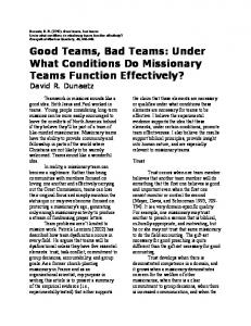
5.1.1 Box-Pushing Evaluation We here examine the use of the relation tool in the cooperative pushing task. Here, we contrasted three interfaces: a split-camera view only, a combination splitcamera and relation tool, and the use of the relation-tool alone. Nineteen human operators were tested on all three interfaces, again scrambling the order of their introduction to the different interfaces to prevent biasing the results due to human learning. Their performance was measured as the average absolute angle deviation from the imaginary horizontal line connecting the robots when they maintain ideal relative velocity. This angle was sampled at 20Hz during task execution. The results are averaged for all operators. However, the operator seeks to make the two pushing robots as horizontal as he could. In another words the operator goal is making the robots pushing at the same force. One robot is working autonomously, changing its velocity in respect to the box distance. The second robot is teleopereted. The operator must be careful not to push too quickly for the other robot, nor to lag behind. The results of this experiment are shown in Figure 5.1. The figure shows the average absolute angle error, averaged across all operators. Clearly, both combinations that use the relation tool are significantly superior to the interface relaying on camera alone. Moreover, the surprising results here is that the relation tool by itself is sufficient (in fact, even slightly better then its combination with the split view). This is due to this task being essentially a pure-coordination task: The operator does not need to worry about where the pushed object is going, as long as the relative velocity of the robots is maintained at 0 (i.e., their velocities are equal). Thus even a socially-attentive display by itself is sufficient. On the other hand, the non-social split-camera view (by itself), is difficult to use for coordination. A one-tailed t-test (assuming unequal variance) shows that the difference between using the tool by itself, and using the split camera view alone, is statistically significant. The probability of the null hypothesis is ρ < 0.014 when looking at the difference in the number of failures. In addition the standard deviation of the non-social split-camera view was 7.11 while any combination with the socially attentive display decrease unequivocally the standard deviation ( 0.79 in "only tool" and 0.93 in "split+tool").
29
7
Split&Tool Only Tool split
deviation[degree]
6 5 4 3 2 1 0 methods
Figure 5.1: Cooperative Pushing: Total failures We also want to measure the angle error results with respect to task completion time. The deviation from the ideal course (where the robots always synchronize pushing the box) is difficult for measuring (due to a physical aspects). Thus we needed to stop the operator (and time) at an estimated distance equivalent to the length of the ideal course. Because of the distance estimation our time measurement here is not accurate but it gives us an overall understanding of the operator control in this domain (a domain where the split camera view is not provide necessary data). Figure 5.2 shows the results of this experiment as average absolute angle error versus time to complete a 180cm walk. The Y axis is the average angle error and the X axis is the time for complete the task. Indeed, the shortest time for completing the 180cm walk was by the method that does not use our sociallyattentive display (the split view). By the Y axis we can see that this method has the maximum average angle error. The average angle error criteria shows the reason the split view scheme finish the task as quickly as possible. We believe that this happens because the operator has no idea what is the parallel state between the two robots, so she pushes the teleoperated robot as quickly as possible, finishing the course as quickly as possible (but poorly).
30
7 6
Only Tool Split&Tool split
Angle dev
5 4 3 2 1 0 48
50
52
54
56
58
60
Time[sec]
Figure 5.2: Cooperative Pushing: Failures vs task completion time
5.1.2 Coordinated Movement Evaluation We evaluate the contribution of the socially-attentive display in the coordinated movement task. The operator leads the robots in a triangular formation towards a target destination, while avoiding obstacles. If the operator causes the lead robot to turn too sharply, or move too quickly, the coordinated movement may break. We conducted experiments contrasting different combinations (see below) of the socially-attentive display with individual robot display (i.e., their incoming video streams). We ran multiple experiments with novice operators on all combinations. Operators were given an approximate 25-minute training session in operating a single and multiple robots, and only began the experiment when they reported they felt comfortable controlling the robots. Different operators were used for the different tasks (25 for coordinated movement), but every operator was tested with all combinations available in the task they operated. To avoid ordering effects, the order in which operators were exposed to the different settings was scrambled. In no setting were the operators able to see the robots directly while operating them. We compared three interfaces. The first presented the operator with the splitview video streams from all robots (e.g., Figure 3.5-c). We named it split. The second split+view combined the this split-view with the socially-attentive display previously described. The final interface consisted of a single camera (the lead robot’s) and the socially-attentive display. We named it one view. Each of the interfaces was tried with three different obstacle courses. The Easy course (Figure 31
5.3) consisted of an open space with no obstacles at all. The medium course (Figure 5.4) consisted of a single obstacle that had to be by-passed while giving the follower robots sufficient leeway. The difficult course (Figure 5.5) consisted two obstacles which the operator needs to navigate the robots in a slalom between the obstacles. For each of these trials, we counted the number of catastrophic and non-catastrophic coordinated movement failures, time for complete the task. Non-catastrophic coordinated movement failures were measured as the number of times a follower robot has temporarily lost track of the lead. Catastrophic failures were measured by the number of times the robots reported on permanent tracking failures (not seeing the in front robot ten frames continually), which would then be fixed manually by the experimenter—not the test-subject operator—by moving the robot by hand until it regained its tracking. stop
450 cm
start 90 cm
Figure 5.3: Easy course
Figures 5.6,5.7,5.8 shows the results of this experiment in terms of the average number of non-catastrophic failures per operator, versus the average task completion time. The horizontal axis shows the time (in milliseconds). The range of the horizontal axis in these figures is fixed at 12 seconds. The vertical axis shows the average number of non-catastrophic failures that took place during each of the trials (25 operators). The results show that in all course difficulty settings—easy, medium and difficult— the use of a socially-attentive display is preferable to using only individual displays. This lends support to the hypothesis that socially-attentive display can 32
stop
65 cm
240 cm 150 cm
start
Figure 5.4: Medium course
significantly improve monitoring of robots in coordinated tasks. In particular, both course completion time and the number of failures during execution were generally significantly reduced using the socially-attentive display. In the easy and medium-difficulty courses, the best monitoring approach was single camera and the socially-attentive display. However, in the difficult course the best monitoring approach used both the split-view and the socially attentive display, in spite of the additional information displayed to the operators. We believe that this is due to the operator using the split-camera view to look at obstacles that are being bypassed. Such obstacles were not much of a problem in the other, easier, courses. We leave further investigation of this to future work. Thus in both monitoring tasks, the use of socially-attentive interface (using the relation tool) proved superior to an approach that did not use this tool. These results are statistically significant in all cases (except, time completion task at difficult course). For instance, in the easy course, a one-tailed t-test (assuming unequal variances—see below) shows a significant difference between the use of the single camera view with the relation tool, and the use of the split camera view, both in the number of failures (the probability of the null hypothesis being
33
stop
120 cm
400 cm
150 cm
start
Figure 5.5: difficult course
p < 0.011), and in the time (p < 0.015). Similarly, in the medium course, there are significant differences between these two methods, both in the number of failures (p < 0.04) and in task completion time (p < 0.02). In the difficult course we compare between the tool+split (the winner method of this course) and split. We find tool+split is different in the number of failures (p < 0.014) while it not significant different in time to complete task (p = 0.48). However, a question may be raised as to whether the display qualitatively changes the way the operator interacts with the team. For instance, the experiment results above could also be indicative of the team going slower or faster, but maintaining the same number of failures per second—thus indicating that the drop in failures is due to the team moving faster, not to the display. Figure 5.9 shows the average number of failures per second, in the different courses. Clearly, the easy course is indeed easier than the medium-difficulty
34
120
one view tool&split split
Little losses
100 80 60 40 20 0 46000
48000
50000
52000
54000
56000
58000
Time[msec]
Figure 5.6: Coordinated Movement: Non catastrophic failures versus time in Easy path
120
one view tool&split split
Little losses
100 80 60 40 20 0 38000
40000
42000
44000
46000
48000
50000
Time[msec]
Figure 5.7: Coordinated Movement: Non catastrophic failures versus time in medium path
35
120
one view tool&split split
little losses
100 80 60 40 20 0 60000
62000
64000
66000
68000
70000
72000
Time [msec]
Figure 5.8: Coordinated Movement: Non catastrophic failures versus time in difficult path 0.002 0.0018 0.0016
one view tool&split split
Losses/Msec
0.0014 0.0012 0.001 0.0008 0.0006 0.0004 0.0002 0 Simple
Medium
Difficult
Figure 5.9: Coordinated Movement: Non-Catastrophic failures per millisecond course, which is easier than the difficult course. What we see in the results is that the use of the socially-attentive display does not only lead to a significant reduction in the time and total number of failures (as evident from the previous figures), but also reduces the failure rate. This signifies that the display leads to a qualitative in the way the operator control the robots. Additional evidence for this qualitative improvement in the operator control of the robots is found when we examine the standard deviation values for the number of failures and task completion time. Table 5.1 displays the standard deviation values of the number of failures, for the different courses. Table 5.2 displays the standard deviation values of the task completion time, for the different courses. 36
Course
Split View
Split View and Relation Tool (tool+split)
Single View and Relation Tool (one view)
Easy Medium Difficult
319.45 141.85 144.97
32.65 51.30 66.93
6.59 50.56 138.65
Table 5.1: A comparison of standard deviation in number of non-catastrophic failures. As can be seen, the standard deviation values for the socially-attentive display are generally much smaller than for the split camera display(except the one view in the difficult course). This indicates more consistent values, i.e., less variance between operators in terms of ability to control the robots. In the difficult path, the single camera view with the relation tool has a large standard deviation (though smaller than the one for the split camera view by itself in the number of failures), but the relation tool with the split camera view again has significantly smaller standard deviation. As we can see here, the standard deviation in the tool+split is almost the same in medium and difficult courses in both, standard deviation in non-catastrophic failure and time compilation task (tables 5.1 and 5.2). While the standard deviation in one view is changed (increasing) between the medium and difficult courses. Those results convinced us that the tool +split is the better scheme in the difficult course. This scheme beats the others in time compilation task, in (minimum) failure number and at standard deviation at the difficult course. However the results at the difficult course were not as we expected. We expected that the one view will be the best method in all the courses (in particular at the difficult course because of operator’s increased load). However those results proved that any combination with the relation tool leads to big advantage then any without using the relation tool. We can also say that the one view method is the best at the simple and medium courses, and the tool+split is the best at the difficult course. We also learned that at the difficult course the relation tool does not provide enough information, and the help of the split camera is essentially for better task execution (e.g. gives different angle’s view of the real world). 37
Course
Split View
Split View and Relation Tool (tool+split)
Single View and Relation Tool (one view)
Easy Medium Difficult
25.53 22.37 15.88
12.01 14.68 13.58
9.17 10.68 19.22
Table 5.2: A comparison of standard deviation in task completion time [sec]. 2.5
one view tool&split split
big losses
2
1.5
1
0.5
0 46000
51000
56000
61000
Time[msec]
Figure 5.10: Coordinated Movement: Catastrophic failures versus time in Easy path Figures 5.10,5.11,5.12 shows the results of this experiment in terms of the average number of catastrophic failures per operator, versus the average task completion time. This results are virtually identical to the results of the non-catastrophic failures. Figures 5.16, 5.17, 5.18 show the results of this experiment in terms of the average angle deviation per operator, versus the average distance deviation. The average angle and distance deviation, is from each robot at the ideal place it should be in the coordinated movement (for a perfect triangle). The horizontal axis shows the average distance deviation (in centimeters). The range of the horizontal axis in these figures is fixed at 10 centimeters. The vertical axis shows the average angle deviation (in degree) during each of the trials (25 operators). The results show that in all course difficulty settings—easy, medium and difficult— that any combination with our socially-attentive display is preferable then the split 38
2.5
one view tool&split split
No. big losses
2
1.5
1
0.5
0 38000
43000
48000
53000
Time[msec]
Figure 5.11: Coordinated Movement: Catastrophic failures versus time in medium path
2.5
one view tool&split split
No. big losses
2 1.5 1 0.5 0 63300
65300
67300
69300
71300
73300
75300
77300
Time[msec]
Figure 5.12: Coordinated Movement: Catastrophic failures versus time in difficult path
39
camera view alone. This lends support to the hypothesis that socially-attentive display can significantly improve monitoring of robots in coordinated tasks. From the results (in Figures 5.16, 5.17, 5.18) we cannot sharply determine what (tool+split or one view) control method is preferable. In the easy course the one view has less distance deviation and more angle deviation than the tool+split approach. In the medium course the one view has better results than the tool+split in both angle and distance deviation. In the difficult course the tool+split has better results than the one view in both angle and distance deviation. When tool+split get better results than the one view, it was slightly better. While when the one view gets better results (then the tool+split) it was significantly better. Those results are statistically significantly different in most courses. For instance, in the easy course, a one-tailed t-test (assuming unequal variances—see below) shows a difference between the use of the single camera view with the relation tool, and the use of the split camera view, both in the angle deviation (p < 0.068), and in distance deviation (p < 0.0005). In the medium course the results are significantly different only in angle deviation (p < 0.016), while in distance deviation p < 0.131. In the difficult course we show a significant difference between the tool+split (the best method at this course) and the split (the worst method at this course)–p < 0.026 in the distance deviation and p < 0.042 in the angle deviation. We again find evidence for a qualitative improvement in the operator control of the robots is found when we examine the standard deviation values for the angle deviation and distance deviation. Tables 5.3 and 5.4 displays the standard deviation values of the angle deviation and distance deviation (correspondingly), for the different courses. As can be seen, the standard deviation values for any combination with the socially-attentive display are generally (except the split+view in the medium course at distance deviation) much smaller than for the split camera display. Tables 5.3 and 5.4 show that in the medium course the standard deviation of one view scheme is smaller then tool+split, for both angle and distance deviation. In the difficult course the standard deviation of tool+split scheme is smaller then one view for both. In the easy course the smallest standard deviation changes between those two tables (in the one view and tool+split schemes). 40
Course
Split View
Split View and Relation Tool (tool+split)
Single View and Relation Tool (one view)
Easy Medium Difficult
2.49 3.43 2.40
1.44 3.39 1.44
1.61 1.69 2.35
Table 5.3: A comparison of standard deviation in angle deviation [degree]. Course
Split View
Split View and Relation Tool (tool+split)
Single View and Relation Tool (one view)
Easy Medium Difficult
11.22 6.71 8.20
5.75 7.98 5.63
5.10 3.57 7.15
Table 5.4: A comparison of standard deviation in distance deviation [cm]. In general, we see that the standard deviation results are consistent with our earlier conclusion. We see that the one view achieved the lowest standard deviation in the easy and medium courses, while the tool+split achieved the best result in the difficult course. One exception is found within table 5.3 where tool+split achieved better results than only one view. Figures 5.13, 5.14 and 5.15 show another look on the results, angle deviation error (Y axis) versus time (in milliseconds) to complete the task. The results here are in agreement with the results show in 5.6, 5.7 and 5.8 and support our hypothesis. We also examine the different interfaces (split, tool+split, one view) along a obstacle hit test. This test examines the number of instances where a robots hits an obstacle along the different courses (easy, medium, hard). Our goal here is to find the interface that behave well (minimum obstacle hitting) with respect to the other interfaces. We examine it on 7 different operators. Figure 5.19 shows us the result of the touch box test. We show here that in all courses, the one view interface gets the best results. Figure 5.19 also shows that in the medium course the tool+split interface is worse than the split interface. 41
8
one view tool&split split
Angle deviation [deg]
7.5 7 6.5 6 5.5 5 4.5 4 3.5 3 46000
48000
50000
52000
54000
56000
58000
Time[msec]
Figure 5.13: Coordinated Movement: Angle deviation per time in simple path 8
one view tool&split split
Angle deviation [deg]
7.5 7 6.5 6 5.5 5 4.5 4 3.5 3 38000
40000
42000
44000
46000
48000
Time[msec]
Figure 5.14: Coordinated Movement: Angle deviation per time in medium path 8
one view tool&split split
Angle deviation[deg]
7.5 7 6.5 6 5.5 5 4.5 4 3.5 3 60300
65300
70300
75300
Time[msec]
Figure 5.15: Coordinated Movement: Angle deviation per time in difficult path 42
8
one view tool&split split
Angle[deg]
7
6
5
4
3 10
12
14
16
18
20
Distance[cm]
one view tool&split split
Angle[deg]
Figure 5.16: Coordinated Movement: Angle deviation per distance deviation in Easy path
8 7.5 7 6.5 6 5.5 5 4.5 4 3.5 3 10
12
14
16
18
20
Distance[cm]
Figure 5.17: Coordinated Movement: Angle deviation per distance deviation in medium path
43
8
one view tool&split split
Angle[deg]
7
6
5
4
3 10
11
12
13
14
15
16
17
18
19
20
Distance[cm]
Figure 5.18: Coordinated Movement: Angle deviation per distance deviation in difficult path The (tool+split) interface includes all the interfaces together (relation tool and the split camera view). The operator for this medium course does not need all of the tools together. In addition she can’t concentrate all the tools together (information overload) things that cause an obstacle touch.
5.1.3 Summary Thus in both monitoring tasks—pushing and coordinated movement—a combination of socially-attentive interface (using the relation tool) proved superior to an approach that did not use this tool. We also found that the relation tool helps even in coordinated tasks where the split camera is effective (e.g the coordinated movement scenario). The experiments have shown that the use of the relation tool leads to qualitative change in the failure rate of the operators, and to an improvement in the consistency of task completion time across operators.
5.2 Evaluation of Call-Request Resolution In this section we will evaluate the effectiveness of the distributed approach in locating a stuck robot. In subsection 5.2.1 we compare between the distributed, teleoperated and autonomous approaches in term of time for locating stuck robot. We also tested a combination of the distributed approach and teleoperated approach 44
Obstacle-touch 0.6
one view tool&split split
Touch numbers
0.5 0.4 0.3 0.2 0.1 0 Easy
Medium
Difficult
Methods
Figure 5.19: Coordinated Movement: Number of obstacle touch along the different courses called semi-distributed. In subsection 5.2.2 we evaluate the quick switching control technique. We compare our distributed approach, that allows the operator to quickly switch control, to a distributed approach that did not allow the operator to quickly switch control (called switchDistributed). We find that the distributed quick-switching method significantly decreases the time for locating the stuck robot.
5.2.1 Evaluation of Distributed Call-Request Resolution We now turn to empirically evaluate these call-request resolution schemes. We use all schemes in failure scenarios in the context of a triangular coordinated movement of three robots. In each of the failure cases, we disable one of the robots to simulate a catastrophic failure, not letting it move or communicate. In accordance with previous approaches, a call-request is then issued to determine the whereabouts of the failing robot. We set up three robot failure scenarios. In all scenarios, the right follower robot was disabled, and color marked to allow its detection by the other robots (called active robots) and the operator. A potential advantage of the distributed and autonomous schemes is that they can utilize the robots’ own knowledge of the coordination to locate the stuck robot. In particular, because the robots have moved in coordinated movement prior to the call-request, they may have an easier 45
Robot A 30 cm 75 cm
Robot B
Stuck Robot
(a) Ground Truth
(b) Graphic
Figure 5.20: The predictable place where the stuck robot should be (Easy) Robot A 30 cm Robot B
40 cm
Stuck Robot
(a) Ground Truth
(b) Graphic
Figure 5.21: The semi-predictable place from the location the stuck robot should be (Medium) time guessing their peer’s location then the operator (who needs to orient herself in space via the teleoperated camera). To evaluate the importance of the robot’s coordination knowledge, we experimented with three locations for the disabled robot: The Easy (Figure 5.20) setup placed the disabled robot at approximately where it would be had it just stopped in its tracks prior to the team getting notification of the call request, i.e., a bit farther behind its location within the coordinated movement. The Medium setup (Figure 5.21) placed the robot behind the left follower robot. The Hard setup (Figure 5.22) placed the robot to the left of the left follower robot, and behind it, i.e., completely out of place compared to the coordinated movement. Thus the locations progress from a location easily predictable by the robots, to a location unpredictable to them. We tested 21 human operators with each of the three failure scenarios, using all the resolution schemes previously describes. The ordering of the scenarios was 46
Robot A 30 cm Robot B
52 cm
Stuck Robot
(a) Ground Truth
(b) Graphic
Figure 5.22: unpredictable location of the stuck robot (Hard) randomized between operators to prevent biasing the results. We distinguished two phases: The first phase of the resolution involved recognition of the disabled failure from any distance. The second phase involved its localization by another robot reaching to it. Each scenario began with the simulated disabling of the robot (and issuing of the call request), and ended with its localization by at least one robot—teleoperated or autonomous. For each of failure scenarios and for each method, we measure the time that it would get the operator to recognize the disabled robot in any one of the cameras (the operator uses the split-view interface in this task), i.e., the duration of the first phase. We then measure the time that it takes for an active robot—autonomous or teleoperated—to reach the disabled robot, i.e., the duration of the second phase. Since the motivation behind the distributed control scheme is to reduce the time spent awaiting resolution, we prefer shorter durations. A potential advantage of the distributed scheme is that it utilizes knowledge that the robots may have in locating the disabled robot. In particular, because the robots have moved in coordinated movement prior to the call-request, they may have an easier time guessing their peer’s location than the operator (who needs to orient herself in space via the teleoperated camera). We begin by examining the bottom line–the total time it takes to identify the location of the disabled robot. Figure 5.23 shows the average total duration for the 21 operators. The vertical axis measures the time in seconds, while the horizontal axis shows the three experiment setups. In each, six bars are shown corresponding to the different resolution schemes (left-to-right: Autonomous, semi-distributed,
47
120
100
Time[sec]
80 Autonomous semi Distributed Tele
60
40
20
0 easy
meduim
hard
Figure 5.23: Total Time to Resolution distributed and teleoperated). The results shows that all easy, medium and hard locations, the distributed approach is preferable to the both centralized teleoperation approaches. Full distributed search does better then the semi-distributed approach in all locations, and better or the same than the autonomous approach. Overall, the distributed collaboration between the operator and active robots in the distributed approach proves to be a powerful technique for significantly reducing the time to complete the task of locating the disabled robot. The results have been tested using a one-tailed t-test assuming unequal variances (see tables 5.6, 5.7 and 5.8). In the easy setup, the distributed scheme is not statistically significantly different then the autonomous scheme, and only moderately different (ρ < 0.12) then the semi-distributed and teleoperated schemes. However, as we move to the medium and hard setups, the situation changes. The total time for the distributed scheme is significantly lower then the total time for the autonomous scheme in the letter setups (ρ < 0.00004 and ρ < 0.1 × 10⁻¹¹ , resp.). The distributed scheme does better then the teleoperated scheme in the hard setup (ρ < 0.02), and is moderately significantly better in the medium setup (ρ < 0.13). An examination of the standard deviation in these examples reveals additional lessons. Table 5.5 shows the standard deviation for the different approaches, in the three experiment setups. Each row corresponds to a different method, and each column to different setup. We can see that in the easy setup, the autonomous, 48
Autonomous Semi-distributed Distributed Teleoperated
Easy
Medium
hard
11.21 11.3 11.28 7.68
36.64 5.07 5.16 5.96
23.82 7.78 7.89 15.87
Table 5.5: Standard deviation of call-resolution times. semi-distributed, and distributed schemes all have essentially the same standard deviation, indicating similar performance. However, the standard deviation for the autonomous scheme in the medium setup is much higher than for the other approaches. In the hard setup, both the autonomous and teleoperated approaches suffer from greater standard deviation in performance than the two distributed schemes. This shows an additional benefit of the distributed methods: A more consistent performance (across different operators) in the distributed and semidistributed. The figure also contains other lessons. First, the ability of the robots to use organizational knowledge of the coordinated movement can be useful in reducing the resolution time, and thus in assisting the operator. When the stuck robot was located approximately where it was predicted to be in terms of its position in the coordinated movements, the robots were able to quickly locate it, in fact outperforming the operator in terms of total time (see more below). However, the distributed scheme was superior even in these cases, because even where the robots were not as successful, the operator (working in collaboration with the robots) was able to compensate. This is particularly evident as the difficulty of the difference setups increased, and the location of the stuck robot became unpredictable to the robots. To better understand these results, we should consider separately the results for the first phase of the search (where an identification of the stuck robot remotely was possible), from the second phase, in which an active robot was to approach the stuck robot to localize it. Figure 5.24 shows the results of the different control schemes for the first phase, averaged across operators. The figure measures the average time (in seconds) it took the operator to recognize the disabled robot from afar, in the split-view camera display. In the autonomous approach, the operator 49
8 7
Autonomous semi Distributed Tele
Time[sec]
6 5 4 3 2 1 0 easy
meduim
hard
Figure 5.24: Phase 1 First recognition did not intervene in the operation of the robots, only indicated that the stuck robot was recognized. In the teleoperated scheme, the operator manually turned a robot around until a heading to the remote was recognized. Clearly, all approaches in which robots attempt to orient themselves towards the predicted location of the disabled are superior to a teleoperated (centralized) approach. Note that in all approaches, the operator recognizes the robot from afar, and as we will see below, may end up searching for it in wrong location. This significantly shorter initial recognition is a beneficial side-effect of the distributed approaches. However, the initial benefits of the robots to orient themselves towards the stuck robot is lost in more difficult settings. Figure 5.24 also shows the usefulness of human operators: Human ability to recognize the robot from afar is virtually identical in all three difficulty settings. Thus humans bring to bear consistent, robust (thought slow), capabilities. These can be useful in real applications, where the stuck robot may be partially hidden behind obstacles or otherwise not visible at all to the robot. An examination of the second phase of the search (once an approximate heading towards the stuck robot is determined) is also telling with respect to this issue. Figure 5.25 shows the results for this phase, where the task is to arrive within the proximity of the disabled robot. Despite its poor performance in phase 1, the teleoperated approach does quite well in phase 2. This is easily explained—here the disabled robot is already recognized, and the teleoperated approach simply allows the operator to drive the teleoperated robot as quickly as possible, outrunning 50
120
100
Time[sec]
80 Autonomous semi Distributed Tele
60
40
20
0 easy
meduim
hard
Figure 5.25: Phase 2 From initial to localization of stuck robot. Phase 1
0.1 0.0002 Semi-distributed 0.5 Autonomous Teleoperated
Phase 2
Total recognition
0.38 0.45 0.11
0.419 0.11 0.11
Table 5.6: Likelihood of null hypothesis, t-test of call-resolution times between distributed approach in easy stuck location. automatic approaches that move in constant (and typically conservative) speed. Thus again, the operator brings to bear capabilities that cannot be duplicated by the robots. However, the best performances was by the distributed approach, because it essentially turns this phase into a race between a teleoperated robot and an autonomous robot, as to who gets to the disabled robot first. In the first phase the results of the Autonomous were better than the Teleoperated. In the second phase vise versa. The Distributed and semi-distributed schemes enjoys the advantage of the autonomous scheme in the first phase and the benefit of the teleoperated scheme in the second scheme. Tables 5.6, 5.7 and 5.8 shows the one-tailed t-test (assuming unequal variances) between our distributed control approach to the other mentioned control approaches in phase 1, phase 2 and global recognition. Tables 5.6, 5.7 and 5.8 compare the above in easy, medium and hard stuck robot location correspondingly.
51
Phase 1
0.266 0.0001 Semi-distributed 0.49 Autonomous Teleoperated
Phase 2
Total recognition
0.00003 0.34 0.11
0.00003 0.12 0.102
Table 5.7: Likelihood of null hypothesis, t-test of call-resolution times between distributed approach in medium stuck location.
Autonomous Teleoperated Semi-distributed
Phase 1
Phase 2
Total recognition
0.014 0.025 0.297
6.8E-15 0.035 0.481
5.4E-15 0.019 0.453
Table 5.8: Likelihood of null hypothesis, t-test of call-resolution times between distributed approach in hard stuck location. In the all (medium, medium and hard) locations there is a significant change between the distributed to the teleoperated approaches in the first phase while there is no significant difference at the second phase. In the medium and hard locations there is a significant change between the distributed and the autonomous approaches in the second phase while there is no significant difference within the first phase. The reason for this is that in the first phase, our distributed approach adopts the autonomous approach. This leads it to behave like the autonomous at the first phase (where the autonomous approach is the quickest in this phase). In the second phase our distributed approach adopts the teleoperated approach, leading it to behave like the teleoperated at the second phase (where the autonomous approach is the quickest in this phase). The above explanation raises questions about the significance of the autonomous results in the second phase at the easy location (see table 5.6). We expected it to be significant (and not ρ < 0.38). We believe it happened because the stuck robot location here is easy and the operator quickly made this task, so it difficult to distinguish between those two phases here. Despite the fact that the semi-distributed scheme takes advantage of the Autonomous and Teleoperated schemes (the autonomous in the first phase and the teleoperated in the second phase) its performance was equal to the teleoperated 52
scheme at the easy and medium setups. That is the cause of losing the advantage of teamwork in the second phase (here, the only active robot is the controlled robot). While in the distributed scheme there is always teamwork (in the first and second phases), an additional advantage that leads it to the best performance. Indeed, contrasting the results of the Autonomous and Distributed approaches is telling. As we move from the easy location to medium to hard, the gap between the methods shrinks and begins to favor the Distributed approach. This happens as a result of the inability of the Autonomous approach, to locate the stuck robot in unpredictable places. The collaboration between the human operator and team is superior to either, alone.
5.2.2 Evaluation of Control Switching We now turn to empirically evaluate the quick switch control compared to the previous method. Without this approach, the operator would need to manually perform several preparatory actions (like, manually turning off a behavior) in order to teleoperate a robot. To test the effects of the control-switch methods, we added two control schemes: switchSemi-distributed and switchDistributed. This two control schemes are similar to the semi-distributed and distributed control schemes correspondingly except the transfer from the part of identifies the stuck robot in one of the displays to teleoperate one robot. If the operator in the switchSemi-distributed and switchDistributed approaches want to teleoperate a robot she needs to turn off it search behavior manually. While in the semi-distributed and distributed approaches its automatically happens and the search behavior is paused. The semi-distributed and distributed is use our quick-pause technique and the switchSemi-distributed and switchDistributed use the old manually technique. We tested 21 human operators with each of the three failure scenarios (as described in the previous section), and compare there results with 9 operators in the manually switching technique. The results is shown in figure 5.26 (leftto-right: switchSemi-distributed, switch-distributed, semi-distributed and distributed) shows the total time to complete the action (First and second phase). We compare each method to its corresponding method (i.e. SwitchSemi with semi53
40 35
SwitchSemi SwitchDistributed semi-distributed Distributed
Time[sec]
30 25 20 15 10 5 0 easy
medium
hard
Figure 5.26: Switching methods comparison of total time to resolution distributed, SwitchDistributed with Distributed). The SwitchSemi and SwitchDistributed are the manually switching methods. We can clearly see that the manual switching method is the worst method. We can also observe that the semi-distributed results were better than any result of the manual switching method in the medium and hard courses. This supports our hypothesis that the control switching is faster than the distributed approach. A closer look at the results shows that in the first phase all methods performed comparably well as can be seen from figure 5.27. This is because they all are based on the same method (operator recognize the stuck robot at the display of the autonomous robots). The differences become apparent in the second phase (Figure 5.28). The problem arises during the control switching from the first to the second phase. The switching here includes two main steps. First, the time it takes to switch from autonomous behavior to teleoperated control must be considered. A secondary issue arises due to this time loss. As the robots act autonomously until the operator assumes control, robots can often take a number of steps after their initial recognition. This results in the robots moving away from the location of their first recognition. We refer to this cascading failure as a secondary failure. Table 5.9 shows the difference and ratio between the distributed and SwitchDistributed methods at easy, medium and hard courses. The results of this table attempt to isolate the delay due to the switching control between the distributed and SwitchDistributed methods. As we previously mentioned the quick switching technique saves not only the switching time, but also the time resulting from the 54
6 5
Time[sec]
4 SwitchSemi SwitchDistributed semi-distributed Distributed
3 2 1 0 easy
medium
hard
Figure 5.27: Switching methods comparison of phase 1 First recognition
35 30
Time[sec]
25 SwitchSemi SwitchDistributed semi-distributed Distributed
20 15 10 5 0 easy
medium
hard
Figure 5.28: Switching methods comparison of phase 2 From initial to localization of stuck robot.
55
difference ratio
Easy
Medium
hard
3.905 1.21
2.84 1.15
9.015 1.39
Table 5.9: Difference and ratio between distributed and SwitchDistributed methods secondary failures. We hypothesized that these secondary failures exist, and constitute a non-fixed time. In order to support this claim, we studied the ratio between the distributed and SwitchDistributed techniques. As Table 5.9 demonstrates, the difference and ratio between these methods varied. Under this assumption that normal switching behaviors require a fixed amount of time this result implies that another factor exists that accounts for this variable length. We concluded that these secondary failures exist, and were not only caused by the time the operator to switch the robot’s behavior. We believe these secondary failures resulted from the robot’s movement after the time it first recognized the stuck robot which caused the operator to reorient the robot. This is responsible for the variable length of lost time. As a result, we proceeded to determine if the switching technique can minimize the length of these failures. The results have been tested using a one-tailed t-test assuming unequal variances. The Switch-Distributed scheme was not statistically significantly different for all courses (easy: ρ < 0.2, medium: ρ < 0.3, hard: ρ < 0.12) in respect to the distributed. The switchSemi-distributed scheme is statistically significantly than the distributed in all courses (easy: ρ < 0.012, medium: ρ < 0.006, hard: ρ < 0.05). An examination of the standard deviation in these examples reveals additional lessons. Table 5.10 shows the standard deviation for the different quick and manually, distributed and semi-distributed approaches, in the three experiment setups. We can see that in the easy setup, there was a small advantage for the manually semi-distributed (switchSemi-distributed) approach. However, the standard deviation of the quick switching approaches (distributed and semi-distributed) in the medium and hard setups is much smaller than for the manually switch approaches.
56
switchSemi-distributed Switch-Distributed Semi-distributed Distributed
Easy
Medium
hard
10.02 11.43 11.3 11.28
9.27 14.87 5.07 5.16
17.76 20.04 7.78 7.89
Table 5.10: Standard deviation of call-resolution times. 120 100
Time[sec]
80 Autonomous SwitchSemi SwitchDistributed
60 40 20 0 easy
medium
hard
Figure 5.29: Switching methods total time comparison with autonomous Combining these results and with the previous section’s standard deviation results (see table 5.5) reveals an additional conclusion – the control approach needs to be distributed and the switching from autonomous behavior to teleoperated should be fast. That will lead to consistent performance (across different operators) in the distributed and semi-distributed methods. The results in Figures 5.29 and 5.30 clarify the advantage of the quick switching control. Here, we compare the manually switch methods with the autonomous and teleoperated methods. We can see that the SwitchDistributed method does not give a substantial advantage over the autonomous approach and not any advantage over the teleoprated approach. While in previous (Figure 5.23) we compare the distributed and semi-distributed with the autonomous and teleoperated methods and find the results significantly in favor of the (quick) distributed approach. The conclusion is therefore that a distributed approach must include a quick switching control technique.
57
40 35
Tele SwitchSemi SwitchDistributed
Time[sec]
30 25 20 15 10 5 0 easy
medium
hard
Figure 5.30: Switching methods total time comparison with teleoperated
58
Chapter 6 Conclusions and Future Work This thesis takes steps towards techniques that allow a single human operator to control a team of robots that are tightly coordinated. In particular we point at two challenges that are unique to controlling tightly-coordinating teams: Explicit monitoring of the coordination, and resolving calls for operator attention. Existing techniques do not adequately address these challenges. Specifically, in such settings, their centralization of the operator as the only entity capable of resolving calls for attention is inappropriate, because it does not take advantage of the teamwork of the robots, and their implicit or explicit organizational knowledge. We demonstrate three techniques. First, we show that socially-attentive displays can significantly improve the number of failures, task completion time and failure rate in two tasks requiring maintenance of team coordination by the operator. Second, we show that a distributed control scheme, allowing teamwork between the operator and all robots, reduces the time of resolving failures (compared to the centralized and autonomous approaches), in many instances. Third, we allow the operator to switch quickly control between the robots, to prevent from cascading failures. For the first technique we find the relation tool is a simple an effective tool addressing this challenge. It has three main advantages. First, it significantly reduces the amount of inference needed by the operator to infer the relative state of robots—and thus the state of coordination between them. Second, it is not limited to reproducing a global view of the robots, but instead its dimensions can
59
be used to directly provide the operator with information about what is going wrong (in case of failure), e.g., as in the coordinated movement case. Third, it can easily complement other types of displays useful for the task, such as any that show the heading or distance left to the destination. We find the distributed approach that combines the second and third techniques significantly better then the other control approaches. Those, working as a team and quick control switch, the operator can take advantage all its resources (i.e. the robots) as smoothly as possible to solve problem. We conducted extensive experiments with up to 25 human operators to empirically evaluate the relation tool and up to 21 human operators for evaluating the different control schemes. We have shown that socially-attentive displays significantly improves the total number of failures, and task completion time in two tasks requiring maintenance of team coordination. Furthermore, we have shown that the use of the relation tool leads to qualitative change in the capabilities of the operator. Not only do failures and completion time decrease, but the failure rate (failures per second) improves significantly as well. In addition, methods utilizing the relation tool show less variance in terms of operator performance. The results of the control schemes shows that the distributed control scheme allows teamwork between the operator and all robots, reduces the time of resolving failures (compared to the centralized and autonomous approaches), and was superior in all cases. We also found that the SwitchDistributed method give not enough advantage then the autonomous approach and not any advantage then the teleoprated approach. So the quick switch control is essentially for controlling multiple robots. The results presented in the thesis also raise questions for future work. For example, the results for the relation tool in the difficult course indicate that while a socially-attentive display can be a significant advantage, it must complement regular displays. A key question is how to best integrate these displays. In addition it need further investigation of the phenomena that the split+tool has less noncatastrophic failure then the split view at the medium course, while it has more catastrophic failure in the same course. For the control scheme, we are particularly interested in integrating the new techniques with complete human-robot interaction systems, in order to evaluate its 60
effectiveness not only within call-request resolution, but in more general settings of operating the robots even in non-failure cases.
61
Bibliography [1] J. A. Adams. Human Management of a Hierarchical System for the Control of Multiple Mobile Robots. PhD thesis, University of Pennsylvania, 1995. [2] K. S. Ali. Multiagent telerobotics: Matching systems to tasks. PhD thesis, Georgia Institute of Technology, 1999. [3] H. Asama, A. Matsumoto, and Y. Ishida. Design of an autonomous and distributed robot system: Acters. In Proc. of the 1989 IEEE/RSJ International workshop on intelligent robots and system, pages 283–290, 1989. [4] M. Fields. Modeling the human/robot interaction in onesaf. In Proceedings of the 23rd Army Science Conference, 2002. (Poster). [5] T. Fong, C. Thorpe, and C. Baur. Multi-robot remote driving with collaborative control. IEEE Transactions on Industrial Electronics, 50(4):699–704, August 2003. [6] T. W. Fong, C. Thorpe, and C. Baur. Collaboration, dialogue, and humanrobot interaction. In Proceedings of the 10th International Symposium of Robotics Research. Springer-Verlag, November 2001. Lorne, Victoria, Australia. [7] C. A. Johnson, J. A. Adams, and K. Kawamura. Evaluation of an enhanced human-robot interface,. In Proceedings of the 2003 IEEE International Conference on Systems, Man, and Cybernetics, Washington, DC, 2003. [8] G. A. Kaminka and M. Tambe. Robust multi-agent teams via sociallyattentive monitoring. 12:105–147, 2000. 62
[9] H. K. Keskinpala and J. A. Adams. Usability analysis of a pda-based interface for a mobile robot,. Human-Computer Interaction, 2004. [10] H. K. Keskinpala, J. A. Adams, and K. Kawamura. Pda-based humanrobotic interface. In Proceedings of the 2003 IEEE International Conference on Systems, Man, and Cybernetics, Washington, DC, 2003. [11] R. Murphy, J. Casper, M. J. Micire, and J. Hyams. Mixed-initiative control of multiple hetrogeneous robots for urban search and rescue. submitted to IEEE Transactions on Robotics and Automation, 2000. [12] K. L. Myers and D. N. Morely. Human directability of agents. In Proceedings of the First International Conference on Knowledge Capture, K-CAP 2001, Canada, 2001. [13] Y. Nakauchi, T. Okada, N. Yamasaki, and Y. Anzai. Multi-agent interface architecture for human-robot cooperation. In Proc of the 1992 IEEE International Conference on Robotics and Automation, pages 2786 – 2788, 1992. [14] D. R. Olsen, Jr., and S. B. Wood. Fan-out: measuring human control of multiple robots. In Proceedings of the 2004 conference on Human factors in computing systems, pages 231–238. ACM Press, 2004. [15] L. E. Parker. ALLIANCE: An architecture for fault tolerant multirobot cooperation. IEEE Transactions on Robotics and Automation, 14(2):220–240, April 1998. [16] P. E. Rybski, I. Burt, T. Dahlin, M. Gini, D. F. Hougen, D. G. Krantz, F. Nageotte, N. Papanikolopoulos, and S. A. Stoeter. System architecture for versatile autonomous and teleoperated control of multiple miniature robots. In Proceedings of the IEEE International Conference on Robotics and Automation, May 2001. [17] P. Scerri, L. Johnson, D. Pynadath, P. Rosenbloom, M. Si, N. Schurr, and M. Tambe. A prototype infrastructure for distributed robot, agent, person teams. In AAMAS-03, 2003.
63
[18] P. Scerri, D. Pynadath, and M. Tambe. Adjustable autonomy in real-world multi-agent environments. In Proceedings of the International Conference on Autonomous Agents, pages 300–307, 2001. [19] R. Simmons, D. Apfelbaum, D. Fox, R. P. Goldman, K. Z. Haigh, D. J. Musliner, M. Pelican, and S. Thrun. Coordinated deployment of multiple, heterogeneous robots. In Proc. of the Conference on Intelligent Robots and Systems (IROS), Takamatsu Japan, October 2000. [20] T. Suzuki, K. Yokota, H. Asama, H. Kaetsu, and I. Endo. Cooperative between the human operator and the multi-agent robotic system: Evaluation of agent monitoring methods for the human interface system. In Proc. of the 1995 IEEE/RSJ International conference on intelligent robots and systems, pages 206–211, 1995. [21] The Tekkotsu Homepage. www.tekkotsu.org, 2002–2003. [22] A. D. Tews, M. J. Mataric, and G. S. Sukhatme. A scalable approach to human-robot interaction. In ICRA-03, 2003. [23] H. A. Yanco, J. L. Drury, and J. Scholtz. Beyond usability evaluation: Analysis of human-robot interaction at a major robotics competition. Journal of Human-Computer Interaction, 19(1 and 2):117 – 149, 2004. [24] K. Yokota, T. Suzuki, H. Asama, A. Masumoto, and I. Endo. A human interface system fot the multi-agent robotic system. In Proc. of the 1994 IEEE International conference on robotics and autonomous, pages 1039– 1044, 1994.
64