us to check that old features are preserved when adding a new feature to the system. Also, because .... provides a good foundation for stepwise feature introduction. ..... software, in a planning game that lets the customers list and rank the fea-.
Software Construction by Stepwise Feature Introduction Ralph-Johan Back
Turku Centre for Computer Science TUCS Technical Report No 496 December 2002 ISBN 952-12-1097-4 ISSN 1239-1891
Abstract We study a method for software construction that is based on introducing new features to an evolving system one by one. A layered software architecture is proposed to support this method. We show how to describe the software with UML diagrams. We provide an exact semantics for the UML diagrams employed in the software architecture, using refinement calculus as the logical framework and show how to reason about software correctness in terms of these UML diagrams.
Keywords: Feature oriented programming, UML, Software architecture, Layered architecture, diagrammatic proofs, requirements, refinement calculus, correctness
TUCS Laboratory Software Construction Laboratory
1
Introduction
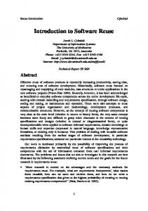
We consider here an approach to software construction that is based on incrementally extending the system with new features, one at a time. We refer to this method as stepwise feature introduction. Introducing a new feature may destroy some already existing features, so the method must allow us to check that old features are preserved when adding a new feature to the system. Also, because the software is being built bottom-up, there is a danger that we get into a blind alley: some new feature cannot be introduced in a proper way, because of the way earlier features have been built. Therefore, we need to be able to change the structure of (or refactor) the software when needed . We will here consider stepwise feature introduction from three main points of view: what is an appropriate software architecture that supports this approach, what are the correctness concerns that need to be addressed, and what kind of software process supports this approach. We use the refinement calculus [1, 17, 9] as our logical basis, but we will not to go in more detail into this theory here, for lack of space. A software system of any reasonable functionality will have a large number of different, interdependet features, and the overall behavior of the software becomes quite complex. We will therefore need good ways of visualizing the structure of software, in order to identify the features in the system, see how they are put together and how they interact with each other. Let us therefore start by describing stepwise feature introduction by means of an analogue. As all analogues, this one is not perfect, but it gives the proper feeling for the overall structure of software. A software system starts out as a village. We think of the village as a collection of houses that are connected by an infrastructure (roads, telephone lines, etc.). The houses correspond to the software components in the system. In the village center, we have service providers, like shops, schools, municipal authorities and so on, each providing some special service that is needed in the village community. We assume that each service provider is located in a house of its own. The service is used by the residential houses in the village, as well as by other service providers in the village. Thus, a software components can be a service provider, a user or both. The village has a development history: it was once founded with just a few houses, and has grown since then with new houses (providing new services or duplicating existing services). Some houses have been torn down, while others have been modified to accommodate changing service needs. Each house has a name (e.g., the street address of the building). A person living in a house can communicate with persons living in other houses using 1
the communication infrastructure (by telephone, mail, or by visiting them). They get service by asking a service provider to carry out some task, or to provide some information (so communication between software components is by message passing). The person is restricted in his communication by his address book (containing mail addresses and/or telephone numbers) and can communicate directly only with the people that are listed there (or with people whose addresses or telephone numbers he gets from other people who already are in his address book).
Bank
Kindergarten
Snacks
Cinema
Main street
Figure 1: A village When the village grows, this simple organization becomes more and more difficult to maintain. The services become more complex, containing more and more specialized services or service features, and there are more and more houses being built. The village is turning into a city. The simple shops in the city center are getting bigger, growing into many-store buildings, with one or more departments on each floor, each department providing some specialized service. For instance, what started out as a simple bank with only one counter, for depositing and withdrawing money from accounts, may grow into a big bank building, where the original service is still available on the ground floor, but on the second floor there is a department for trading with stocks, and on the third floor a department for mortgage loans. The floors of a building correspond to a layering of the software features in a component. At the lower floors are services that have been needed early on, while higher up are specialized services that have been created more recently. We assume that the building technique used for houses in the city is very flexible, so that whenever one needs to extend the service provided by a service provider, one can simply build a new floor on top of the house. It is also easy to tear down a floor, if it is not needed any more. A new service may depend on some older service, provided lower down in the building, but it may also replace some earlier service . We will assume that anybody who contacts a department at some floor will have access to the specialized service provided by that department, but also has access to all the service provided by the departments in the floors below. We assume that a customer that wants a service always contacts the top floor of the building (e.g., takes 2
the elevator to the top floor). This floor provides the most recent service features, as well as all older services. When a building is extended with a new floor, to provide some additional service, it may require some new service from other service providers in the city. These new service features may either be provided by newly built houses, or by existing houses that are extended with new floors to provide the additional service. Thus, introducing a new service may lead to a small building boom where a number of houses are built or extended at the same time, to provide for related services. The building material used in the houses ages quite rapidly and visibly, so that one can clearly distinguish the houses and extension floors build during one building boom from those built during other booms. In this way, the houses in the city center will get a curious striped appearance, not usually seen in city planning. The related service features in the different buildings show up as a layer in the city scape. (Repairing a house or a floor does not affect the outer appearance of the house, so this pattern is preserved also by renovations). Real estate Bank
Kindergarten Snacks
Cinema
Main street
Figure 2: City scape The departments are very conservative, in the sense that once they have decided to get service from some other service provider, they will not change the service provider, or request new service from the provider. In particular, this means that a department in a specific layer will not make use of the new service features that are made available by service providers on layers that have been built later. The department can communicate with floors on later layers, because these floors provide all the service features of lower layers, but it does not request any service features that have been introduced after its own layer was built. Of course, a layer higher up in the service provider that the department uses can redefine the contents of an existing service feature, so that the service the department gets is in fact different. The conservatism implies that each layer can function without the layers that have been built 3
later, continuing together with the lower layers to provide the service that was made available when the layer in question was built. The development of the city is evolutionary, with new layers being built on top of existing ones, without changing the old layers. Sometimes, however, it becomes too difficult to just simply add a new service feature on top of the existing ones. In these cases, one may need to reconstruct part of a building or maybe even part of the city, by changing the layers and the service features they provide so that it becomes easier to add the new service features. This corresponds to software refactoring [14]. The city planning authorities insist, however, that the restructuring should be done in such a way that the layered structure of the city is preserved. In particular, each layer should after the reconstruction be able to function without dependence of the layers higher up in the hierarchy, providing all the service features of its own and lower layers. This picture emphasizes the gradual evolution of a software system towards better and more powerful functionality, punctuated with larger refactorings when the layering scheme runs into trouble. The process is such that the system is always kept functional: at each stage, the system may only have a subset of the desired features implemented, but those that are implemented work ok. Throughout the development, each layer provides a working version of the overall system, with a certain subset of the desired overall service, but which can be tested, experimented with and even used in production. Hence, the system is useful already while it is being built, and the construction and testing of the system can proceed in parallel with its use. The picture also emphasize a four dimensional view of the city (and of software). Two dimensions are formed by the city buildings, how they are laid out on the map in the city, and how they communicate with each other. It corresponds to a view of the city from above. In software, this view will correspond to a UML class diagrams. A third dimension is added by the layering of the city, corresponding to a view from the side, the city scape. We will capture the layering as regions in UML class diagrams [12]. A final fourth dimension in the city is time, captured by the history of the city, how it has been developed. In software, this dimension is captured by the successive software releases, showing both the slow evolutionary changes and the more drastic software refactorings that have been carried out while constructing the software. The stepwise feature introduction method has much in common with the original stepwise refinement method [13, 18]. A large programming problem is broken up into a number of smaller programming problems. Solving these smaller problems one by one will build up the solution to the original problem 4
in an incremental fashion. As in the stepwise refinement method, we hope to make the overall structure of the software system clearer and more easy to understand, make it easier to check its correctness and easier to maintain and adapt the system to changing requirements. Another similarity is that we also emphasize that the software should be checked for correctness while it is being built, rather than in a separate phase after it has been built. A main difference to stepwise refinement is again that we are building the system bottom-up rather than top-down. Also, our emphasis in on objectoriented programming techniques, while stepwise refinement was designed for procedural programs. However, we will show that refinement calculus, originally developed as the logical foundation for stepwise refinement, also provides a good foundation for stepwise feature introduction. In the following sections, we will try to make this picture more precise. We will first describe how to build features into software in layers, and how to argue about the correctness of a system build in this way. We will look at how to describe specifications and implementations in this approach, how to express requirements and how to organize testing of layered software. We will then also describe a diagrammatic approach to reasoning about correctness in layered systems. We will finally give some comments on a software process that supports stepwise feature introduction and also relate some initial experiments from using this software construction method in practice.
2
Feature extensions, layers and components
A software component provides a service. The service consists of a collection of (service) features. From a programming language point of view, a feature will be implemented as a class that (usually) extends one or more other classes. This class introduces a new feature while at the same time inheriting all the features introduced in the classes that it extends. For instance, assume that we have a class that provides a simple text widget in a graphical user interface. This text widget can be placed in a frame in order to be shown on the screen, and it provides service for manipulating the text it contains with the mouse and from the keyboard. The text can be manipulated by inserting new text into it, deleting text, selecting text, and moving the insertion point by clicking the mouse or using the cursor keys. The text widget only works with simple ascii-text. We can think of a number of features by which we can extend the service provided by this simple text widget, like the following: saving Save the text in the widget to a file, or replace the text in the widget with the contents of a file. 5
cut and paste Cut (or copy) a selected piece of text into the clipboard, and paste the contents of the clipboard into the place where the insertion cursor is. styles Format pieces of text in the widget, e.g. by changing the selected text to boldface, italics, underlined, or colored text. Extending the simple text widget with a cut-and-paste feature will give us a new text widget that is able to do all the things that the original text widget does, and in addition allows cut, copy and paste in the text. Adding this new feature to the text widget has to be done very carefully: not only do we have to change the original text widget so that cut-copy-and paste is now possible, but at the same time we have to be careful to preserve the old features. Not preserving some old feature, or corrupting it, is considered an error. We refer to this step as a feature introduction step. Consider another extension of the simple text widget, where we add styles to the text. Again, we get a new text widget, with all the features of the original text widget, but which in addition is also capable of showing styled text. Hence, for correctness, we need to show that styles are correctly implemented, and that the old features have been preserved. Adding cut-and-paste and adding styles are two independent extensions of the simple text widget. We can then construct a new class that inherits from both the cut-and-paste text widget and from the styles text widget, using multiple inheritance. We have to be careful here, however, because inheritance alone is probably not what we want. In this case, the cut-andpaste operations were defined for ascii-text only, so cutting and pasting does not take the styles of the text into account (i.e., only the ascii text is copied, not the styles for the text). What we really want is to copy and paste the styles also. This means that we have a feature interaction: the two independent features cannot be combined directly, because they interact in an unwanted way. A feature combination step will resolve this unwanted feature interaction. It is a class that extends both the cut-and-paste text class and the style text class, by overriding the behavior of the methods in these classes so that the new features interact in the desired way (here that the styles are also copied and pasted). Sometimes this step can be very simple, at other times feature combination can require a major effort. The reason for introducing these two features in two separate steps is that we want to separate our concerns. First, we want to work out how to add cut-and-paste to a simple ascii text widget, without the complications of styled text. Then, we want to consider how to add styles to text, without the complications of also having to consider cut-and-paste of the text. Once we have worked out the implementations for these two features, we are ready 6
to tackle the problem of how to combine the two features. This will usually mean that part of the code for each feature has to be modified (by overriding some methods) to take the other feature into considerations. However, this is easier to do once the code for each feature in isolation has been explicitly written out and is open for inspection and analysis. The feature introduction and feature consolidation steps are shown in Figure 3. feature combination
feature introduction
BetterText
CutAndPaste
Styles
SimpleText
Figure 3: Feature introduction and combination Feature combination is thus realized by multiple inheritance, while feature introduction is realized by single inheritance. Feature combination and feature introduction are similar in that in both cases, the features of the superclasses have to be preserved. An alternative way of building up the better text widget would be to introduce first one feature, and then the other as an extension of the first feature. This means that we need to decide in which order the two features should be introduced. The alternative approaches are illustrated in Figure 4, where extension is indicated by stacking boxes on top of each other. It is not BetterText
Styles
CutAndPaste
CutAndPaste
Styles
SimpleText
SimpleText
SimpleText
(a)
(b)
(c)
CutAndPaste
Styles
Figure 4: Alternative extension orders clear which alternatives is best. Alternative (a) avoids an arbitrary choice between which feature to introduce first, and allows us to consider the two features in separation. On the other hand, it requires a combination step. Alternatives (b) and (c) introduce one feature before the other. This avoids the combination step, so the resulting hierarchy will be simpler, but this 7
can happen at the expense of making the second feature more difficult to introduce. A component is divided into layers, where one layer can be the combination of a number of independent feature introductions followed by a feature combination step, or just a single feature introduction. A layer will often cut across components, so that the same layer exist on a number of related components. In stepwise feature introduction, the software is constructed layer by layer, with the components in the same layer designed to work together. As an example, consider again the text widget. Now assume that we are also building an editor that will display this text widget. The editor will contain a pane that shows the text widget, but it will also have a menu for manipulating the text widget. In the first layer, we will have the simple text widget, and an editor which only can display this widget, maybe with a simple menu that only permits quitting the application. This simple editor can in fact also use the feature extensions of the text widget, the cut-andpaste extension and the style extension, and also the combination of these two extensions, the better text widget. However, the user of the simple editor cannot make use of these features, because there are no menu choices by which the new features can be activated. To access these new features, we need to construct an extension of the simple editor (a better editor), which has an edit menu for the cut-and-paste operations, and a style menu for setting and removing styles in the text. The situation is illustrated in Figure 5. Here we use directed arrows to indicate the situation where one class (here the Editor classes) can use another class (here the Text classes) by sending messages to it. content BetterEditor
BetterText
CutAndPaste
Better layer Simple layer
content SimpleEditor
SimpleText
Editor component
Text component
Figure 5: Interacting components 8
Styles
The new editor is, however, restricted to only work on the better text widget, because the features that it assumes in the menus are only available on this level. Hence, there are two layers in the design, the Simple layer and the Better layer. The layers are not part of the standard UML notation, but they can be indicated by regions in the diagram. Figure 6 shows the architectural design with components and features, split into layers. Here content Better layer Simple layer
BetterEditor
BetterText CutAndPaste
SimpleEditor
content
Editor component
Styles
SimpleText Text component
Figure 6: Layers and components the layers are defined by horizontal lines. This diagram emphasizes the two primary components, the text widget and the text editor.
3
Correctness concerns
We will assume that the classes that make up the software are annotated with information about how the classes are intended to be used. In particular, we assume that each class has a class invariant, which expresses the conditions on the attributes that must be established when the class is instantiated, and which must be preserved by each operation on the class. Also, we assume that the methods of the class have a precondition which states the assumptions that must hold when the method is called, and possibly a postcondition, which expresses properties that hold when the method call returns. These are all annotations that are assumed in, e.g., the design by contract approach advocated by Meyer and others [15]. A class that implements a feature must satisfy certain conditions in order to be correct, in the sense that it provides a solid step on which other extensions can be built. The main conditions that have to be satisfied are four: Internal consistency The class must be internally consistent, in the sense that it respects the constraints that are indicated for its part. The most important constraint is that it has to respect its class invariant. Other constraints that may be given in the class are loop invariants and postconditions for methods. In proving internal consistency, it may be assumed that the preconditions for the methods are satisfied upon start 9
of the method. Besides the safety properties expressed as invariants, consistency also requires that each method invocation terminates. Respect Besides being consistent with its own constraints, one also has to show that the class respects the constraints of other classes that it uses. This means in particular that the class has to satisfy the preconditions of all the methods that it calls. For dynamically typed programming languages, one also needs to check that the typing is correct, in the sense that no illegal operation is attempted on an object during execution. In practice, this has to be done also for statically typed languages, because the type system provided by the language is usually too crude, and one needs to make finer distinctions in the code (soft typing). Preserving old features One also needs to show that a feature extension preserve the features of the superclass, i.e., that it is a superposition refinement of the superclass. An arbitrary subclass will not automatically be a superposition refinement, it has to be designed and proved to be one. Satisfies requirements The feature has been introduced for a specific reason, i.e., we have certain requirements that need to be realized by the feature. We therefore also need to show that the feature does in fact satisfy the requirements given for it. A feature extension may satisfy all the previous correctness criteria, but still not be what we want, so this is also a crucial condition. In carrying out these proof steps, we are allowed to assume that all features on lower layers do satisfy their corresponding requirements. If we prove that each feature extension satisfies these correctness conditions, then by induction, it will follow that the software system as a whole will satisfy these four correctness conditions. Note that the final software system will be represented by one feature extension class, for which we then have shown the above properties. We will express the correctness conditions and reason about their satisfaction in the refinement calculus [9]. We will in this paper not go deeper into the formalization of the stepwise feature introduction method in the refinement calculus, as this will be considered in more detail elsewhere.
4
Specifications, Implementations and Views
The BetterText class described above may not be the only way in which we can construct a class with the required functionality. Maybe there is a 10
class library around with a text widget that already has this functionality. Or maybe the BetterText widget is ok as a description of what we want to achieve, but it is not efficient enough. We can then consider the BetterText widget as a specification of the service that we want, to be implemented by another class (or maybe we want to have different implementations of this service around). This is illustrated in Figure 7. Here we have implemented Better layer
Efficient layer BetterText
BetterEditor
CutAndPaste
SimpleEditor
EfficientText
Styles
SimpleText
LibraryText
Simple layer
Figure 7: Implementing the BetterText widget the BetterText widget with another widget, EfficientText. This text widget in turn makes use of a text widget called LibraryText, from an existing class library. The EfficientText class is essentially a wrapper for the LibraryText widget, translating the method calls for the BetterText widget to corresponding calls to the LibraryText widget, to bridge the differences in interfaces. The figure also shows that the SimpleText can be implemented directly by LibraryText, which we assume has all the methods of SimpleText directly available, so no wrapper is needed in this case. Implementations are indicated in the diagrams by dashed open arrows, going from the implementation to the specification. This figure shows that the specification of the BetterText widget is also built up in layers. Thus, we can use the stepwise feature introduction for constructing the software itself as well as for constructing the specifications for the software components. Many software components are very complex, and provide a number of different, highly interdependent features. The specification of such components can then be simplified by specifying the component one feature at a time, building up the specification in layers, as if it was an executable software component. A more thorough description of layered specifications is given in [7]. 11
We can describe specifications and implementation by our city analogue as well. Consider first SimpleText. It corresponds to a house in the village (or to the bottom floor in a building in the city). If you ask for a service from this service provider, it will pretend to do the service itself, but in reality it is just a front end for another service provider (LibraryText), situated in another city (which has a different layering than our city, or no layering at all). For the BetterText, the same kind of analogue holds: A service request to this department is forwarded to another service provider (in this case EfficientText), and the replies that it gets are given to you as if they had been computed on site. The EfficientText could be in our city, maybe built in a later layer than the BetterText. The user may be under the impression that the service provider is structured as BetterText, but in reality this is just a way of explaining the service that BetterText offers to the user, but is not the way in which the service is actually realized. For correctness of an implementation, we need to show that the implementation is a data refinement of the specification. This can be done using standard data refinement techniques [1, 10, 16, 6], requiring that an abstraction function (or abstraction relation) is given that maps the attributes of the implementing class to the attributes of the specification class. Superposition refinement is a special case of data refinement. A data refinement step may change the collection attributes used in a class to represent the data, adding new attributes and deleting some old attributes. Superposition refinement can only add new attributes, it cannot remove old attributes. Superposition refinement (applied to reactive systems) is described in more detail in [8]. If we prove that BetterText is data refined by EfficientText, then any usage of BetterText in the system can be replaced with using EfficientText, by monotonicity of data refinement. Thus, the diagram in Figure 7 can be simplified to the diagram in Figure 8. Here the BetterEditor is using EfficientText directly, and the SimpleEditor is using LibraryText directly. BetterEditor
EfficientText
SimpleEditor
LibraryText
Figure 8: Using implementation directly A view or interface of a class can also be seen as a specification of that class. For instance, consider the situation shown in Figure 9. Here the Bet12
ReadOnlyText
BetterText
EfficientText
MarkedText
CutAndPaste
Styles
SimpleText
LibraryText
Figure 9: Different views of the BetterText widget terText widget is itself seen as an implementation that supports two different views, one that only allows reading of the text but no changes to it (ReadOnlyText) and the other (MarkedText) that allows highlighting of the text using styles, but does not allow other kind of changes to the text. Views are thus just specifications. ReadOnlyText and MarkedText are thus two different specifications that are implemented by the same class, in this case BetterText. Again, correctness concerns require us to show that both specifications are correctly implemented by the BetterText widget, by showing a data refinement between the corresponding entities. Here we need to show that BetterText is a data refinement of, e.g., ReadOnlyText, while in the previous example, we had to show data refinement in the other direction, that BetterText is data refined by EfficientText. The figure also shows that we can cascade implementations: MarkedText is implemented by BetterText which in turn is implemented by EfficientText.
5
Reasoning based on diagrams
The diagrams that we have been showing above are more or less standard UML diagrams. However, we can also consider these diagrams as proof diagrams, by adding a simple notational device to the diagrams: an exclamation mark next to a diagram entity means that the correctness condition associated with this entity has been established. More precisely, • an exclamation mark in a class box means that the class is internally consistent, • an exclamation mark on one end of an association means that the 13
class in the other end is respecting the usage of the other class, and an exclamation mark next to an attribute that the class is respecting the usage of the attribute, • an exclamation mark on an inheritance arrow means that the subclass is a superposition refinement of the superclass, • an exclamation mark on the implementation arrow means that the implementing class is a data refinement of the original class. We can say that a class, association, inheritance arrow or implementation arrow in a diagram is correct, if we are allowed to place an exclamation mark next to it. A question mark next to a diagram entity means that we do not know if the correctness condition associated with this entity is true. No marking for an entity means that we have not yet considered the associated correctness condition, or prefer to ignore this condition. What it means that the correctness condition has been established can vary from one software project to the next. Sometimes, it just means that we have done a careful check (e.g., a code review) and are convinced that the correctness condition holds here. Sometimes it can mean that we have tested the correctness criterion, and found no violations. Sometimes it can mean that we have carried out a semi-formal or formal proof of the correctness condition. From a given diagram with markings for the correctness conditions that have been established, we can infer other features of the diagram. An example of this was given in Figure 8, where we inferred that we could replace the use of BetterText in the BetterEditor with the use of EfficientText. This inference is shown in more detail in Figure 10. In the upper diagram, we BetterEditor !
!
BetterText !
!
BetterText !
!
EfficientText !
! BetterEditor !
EfficientText !
Figure 10: Reasoning with diagrams indicate that all the classes shown are internally consistent, the association 14
is correct and the implementation is correct. The lower diagram shows that we have changed BetterEditor to use EfficientText rather than BetterText. However, the check marks in the lower diagram are as before, indicating that this change of usage does not invalidate any of the correctness conditions. The fact that the BetterEditor respects the EfficentEditor, as indicated in the lower diagram, follows from the fact that EfficientEditor is a data refinement of the BetterEditor. Data refinement also implies that the BetterEditor component is still internally consistent. As the internal consistency of a component can depend on any semantic properties of the components used, this means that the EfficientEditor satisfies all requirements that the BetterEditor did. Consider now the case where we have not proved data refinement of BetterText with EfficientText. The situation is shown in the upper diagram in Figure 11. The lower diagram now shows that we do not know whether BetterEditor !
!
BetterText !
?
BetterText !
?
EfficientText !
? BetterEditor ?
EfficientText !
Figure 11: Reasoning with less information BetterEditor respects EfficientEditor (even if it did respect BetterText). We also do not know whether BetterEditor itself is internally consistent anymore, because the behavior of the component that it is using may have changed. BetterEditor may be internally consistent, but we have to establish this by a new proof. The transitivity and monotonicity properties of data refinement and superposition refinement mean that we can infer a number of other correct associations and arrows from the existing ones. As these are implicit in the diagram, we do not need to write out them explicitly. In fact, we do not want to write them out explicitly, as they would only make the diagrams less readable, without adding any information that is not there already. We show in Figure 12 some of the implicit correct arrows that can be inferred from the existing correct arrows in Figure 7. The implicit arrows are thin, the given ones are thick. We omit the exclamation marks in the diagram for simplicity. The diagram shows that SimpleEditor also can use BetterText, CutAndPaste 15
BetterEditor
BetterText
CutAndPaste
SimpleEditor
EfficientText
Styles
SimpleText
LibraryText
Figure 12: Implicit correct associations and arrows and LibraryText (among others) as content, respecting these classes. This is a consequence of the monotonicity of ordinary program constructs under refinement. It also shows that BetterText is a superposition refinement of SimpleText directly. In addition, it shows that EfficienText is a data refinement also of Styles and SimpleText (because superposition refinement is a special case of data refinement). These are again consequences of the transitivity of data refinement. An earlier attempt to formalize refinement calculus using diagrams can be found in [3].
6
Requirements and testing
The previous discussion has concentrated on showing that a software system is internally consistent, that components are used in a responsible way, that layering is a superposition refinement in order to preserve features from one layer to the next, and that implementations are data refinements, so that the implementation can be used instead of the specification. But we have not said anything about satisfying requirements yet. The system that we are building might well be working perfectly but doing something completely different than what we intended. We will model requirements by customer classes. An customer of a component uses the service provided by the component in a certain way, checking that the service it gets is what it expected. We can express a service requirement by a statement of the form R = [P ]; S; {Q} 16
Here P and Q are conditions (predicates) on the program variables (object attributes). The assume statement [P ] will succeed directly, if condition P does not hold, but acts as a skip statement otherwise. The assertion statement {Q} will fail directly if Q does not hold, but otherwise it also acts as a skip statement. The requirement R is an executable statement, which may succeed directly (if P does not hold initially), it may terminate in an ordinary way after executing S (if Q holds after executing S), or it may fail, if Q does not hold after executing S. It is also possible to have assume and assert statements inside S, so that execution of S itself may also fail or succeed. An customer class CheckSimpleText for the SimpleText class could be structured as in Figure 13. The customer class can have one method for server
CheckSimpleText createServer checkInsert ...
SimpleText insert get length ...
Figure 13: Checking requirements on SimpleText checking a number of requirements, or a number of methods, one for each requirement. An example requirement is expressed by the method checkInsert, which expresses that inserting text at a specific place changes the text in the appropriate way. This method is defined as follows (using a Python-like syntax []): def checkInsert(self, t,s,i): [0 ≤ i ≤ |t|] server:= self.createServer(t) server.insert(i,s) s1:=server.get() {s1 = t[: i] + s + t[i :]} Assume that the method insert(i, s) inserts string s at position i in the widget, and that get() returns the text string in the widget. The customer expects (and requires) that the method checkInsert should never fail, no matter how initial text string t, the position index i and the inserted string s are chosen. Here t[: i] denotes the prefix of t up to (but not including) i, and t[i :] denotes the suffix of t starting from i. String concatenation is denoted by +. The method createServer creates an instance of the SimpleText class: def createServer(t): return SimpleText(t) 17
Requirements as described above are very similar to unit tests, except that the methods cannot be executed automatically, they require some parameters to be given during call time. A requirement that does not require any parameters can be seen as a test. For instance, the following is a test methods: def testInsert(self): self.checkInsert(”abcdefg”, ”XYZ”,2) As no input parameters are needed, this test can be executed automatically, without user interaction. Consider next the requirements for the CutAndPaste class. We may want to check that cutting a piece of the text and then pasting it to another place has the desired effect. For this purpose, we can define a customer class, CheckCutAndPaste, that has a method that expresses this requirement. This methods could work as follows: def checkCutFollowedByPaste(self,t,i,j,k): [0 ≤ i ≤ j ≤ |t| ∧ 0 ≤ k ≤ |t| − j + i ] server:= self.createServer(t) server.cut(i,j) server.paste(k) s1:= t[:i]+t[j:] s2:= s1[:k]+t[i:j]+s1[k:] {server.get() = s2} In this class, we redefine the createServer method to instantiate an object of class CutAndPaste: def createServer(t): return CutAndPaste(t) We check that class CutAndPaste correctly implements the features that we require, by methods such as checkCutFollowedByPaste . However, when extending the SimpleText with the new cut-and-paste feature, we also need to check that we do not loose any features that we have in the original class. This means that all the requirements that we have expressed for SimpleText should still hold for the new class CutAndPaste. We can check this by defining the class CheckCutAndPaste to be a subclass of CheckSimpleText. In this way, the former class inherits all the requirements expressed as methods in CheckSimpleText. These methods will be applied to an instance of class 18
CutAndPaste, rather than to an instance of class SimpleText, because we have redefined createServer in CheckCutAndPaste. The way the requirements are checked in these cases is shown in Figure 14. The figure shows the two classes being observed, and the two customer classes. The dashed line shows the instantiation of the text widget when SimpleText requirements are checked from CheckCutAndPaste. server
CheckCutAndPaste
CutAndPaste
server server
CheckSimpleText
SimpleText
Figure 14: Layered checking of requirements In general, the customer classes will be structured by inheritance in the same way as the classes of the system itself. This is illustrated in Figure 15, where we have indicated the observation classes as shadows for the main classes. The naming of these observation classes can be uniform, the name being derived from the observed class, so we do not need to indicate the names of the classes here. Also, we do not need to indicate the inheritance hierarchy of the customers, as it is the same as that of the observed classes. An exclamation mark on a customer class indicates that the associated requirements are satisfied. In [5] we describe in more detail methods for testing layered software that has been built by stepwise feature introduction. BetterText
CutAndPaste
Styles
SimpleText
Figure 15: Service providers (light boxes) and customers (dark boxes) Our analogue extends to testing and requirements, by considering the requirements, here modelled as customer classes, as the ordinary houses in the village or city. The inhabitants in these houses are the customers of the 19
services provided by the buildings in the village or city center. The customers can have different requirements on the service. We can have two different customers that make requirements on the same service class, or we can have a customer that make requirements on different service classes. Figure 15 shows the special case with one customer for each service class.
7
Software Process
The stepwise feature introduction method does not fit well with the traditional software process, with its strong separation of requirements analysis, design, coding, testing and maintenance. However, it does fit quite well with the extreme programming approach that has been advocated by Kent Beck and others [11]. Extreme programming is a collection of techniques and practices that together form an interesting software process for small team system development. Among the practices advocated are short iteration cycles in the development, a concentration on producing code rather than documentation, avoiding to plan for future extensions, and frequent testing and integration of software during development. It also encourages practices like pair-programming and on-site customers, in order to create the right dynamics in the software team. Extreme programming also emphasizes the incremental construction of software, in a planning game that lets the customers list and rank the features they need in the software, while the programming team estimates the time and other resources needed to implement each feature. The next iteration cycle is then carried out in a fixed time, and includes only those features that the customer has deemed to be most important and which all can be implemented in the time frame provided for the iteration cycle. However, extreme programming literature does not seem to be very precise about how to structure the software that is developed in this way. Stepwise feature introduction can be seen as a complement to the extreme programming process, describing more precisely how to structure the software and build the components that are developed in the incremental fashion that extreme programming proposes. Extreme programming has also been seen as a new coming of hackerism, as it de-emphasizes documentation and careful design of the software, and emphasizes the coding part of the software process. We have tried above to show that this is not a necessary feature of extreme programming, it is possible to add documentation and correctness concerns as central parts of the incremental software construction process. The stepwise feature introduction method defines the layering structure of 20
the software, but does not take any position on the order in which the layers are built (except the obvious one, that they should be built from bottom up). In particular, we have not said when requirements and tests should be written and when they should be checked. From the correctness point of view, it does not matter in which order the customer classes and the service classes are written, as long as consistency can be proved for all classes and correctness for all arrows. One well-motivated approach generalizes the testing approach in extreme programming. They propose that a tester (unit test class) for a class should be written before the class itself is written. Also, they propose that all tests are executed automatically after each iteration cycle in the software development cycle. Let us look at a this approach in more detail. Referring to the example in Figure 14, each iteration will build one layer in the software. In each iteration, we will define the requirements for the layer, design the layer, code the classes that are needed, and check the correctness of the layer. The sequence for the bottom layer in our text editor could be, e.g., as follows: 1. Construct the class CheckSimpleText that expresses the requirements for a simple text widget, and also contains test cases for this text widget, to be executed once the widget has been written. 2. Construct the class SimpleText, using the requirements and tests in CheckSimpleText as design guidelines. 3. Check that the class SimpleText is internally consistent. 4. Check that the CheckSimpleText class is internally consistent and respect the SimpleText class. This will show that the class SimpleText satisfies its requirements. We can check consistency and correctness by formal or semi-formal proofs, by hand testing the requirements for selected parameter values, or by executing these tests. To build the next layer, which introduces the cut-and-paste feature, we proceed in a similar way, applying steps 1 - 4 to the classes CheckCutAndPaste and CutAndPaste. In addition, we have to continue with two more steps, that are needed for every extension: 5. Check that the requirements for SimpleText are still satisfied, after the cut-and-paste feature has been introduced. We do this by checking the requirements and running the tests inherited from CheckSimpleText, but using an instance of class CutAndPaste rather than an instance of class SimpleText. 21
6. Check that CutAndPaste is a superposition refinement of SimpleText. The above is, of course, a simplification of the actual software construction process. In practice quite a lot of planning is needed to identify the right features to be introduced, plan the layer structure, and solve special technical implementation problems. We have here also not discussed in more detail the need for refactoring of the software, when the layering structure runs into problems. Usually the need for refactoring becomes evident when it becomes increasingly difficult to add new features, with elaborate constructions to get around bad design decisions made in constructing earlier layers. A refactoring will often change the layering structure, sometime more and sometimes less, but the main purpose is to allow the software construction to proceed in a layered fashion after the problematic design decisions have been corrected.
8
Conclusions
We have above described the stepwise feature introduction method in outline. The method in itself is probably not new, a larger piece of software has to be implemented in more or less this way, building one feature at a time. Using inheritance for the layering is also not new, but rather one of the main motivations for having inheritance in the first place. What we have tried here is to make this method more precise, by identifying the correctness conditions that must be satisfied for the final system to be correct. The central idea here is that the layers should be built as superposition refinements on top of each other, i.e., at the same time as new features are introduced one has to check that the old features are preserved. This will distribute the total verification effort over the layers in an even way. A difference between the diagrams that we use and ordinary UML diagrams is that our diagrams have a precise mathematical meaning, being essentially logical statements in the refinement calculus about the classes that make up the software and the relationship between these different classes. We can even describe logical inference steps with the diagrams. Layering in order to make software easier to construct and understand is also a well-known and important technique, often used in large software systems. However, the layers are usually quite thick, containing a lot of functionality and features, whereas we are here proposing that the software should be built up in very thin layers, each layer only introducing one feature at a time. Also, we insist that each layer, together with the layers lower down in the hierarchy, should be able to function on its own, and that this property should be preserved also after restructuring of the software. This means that the software system is really a collection of software systems, 22
with progressively more functionality. When one is having problems with one layer in the software, it is always possible to regress to a lower layer that works correctly, albeit with less functionality than the higher layer. Also, this approach provides an easy way to branch off the software into different directions, providing different sets of extension features on a common basic set of features. Thus, the approach supports the design of software platforms and software families based on platforms. We have also considered in more detail the role of specifications, implementation, requirements and testing in this context. It turns out that these notions are all easily expressed in UML and can be explained in refinement calculus terms. They also fit well into the layered software architecture. We have carried out a few case studies in stepwise feature introduction, and the results have been quite encouraging. In [4], we report on a programming project with 6 undergraduate students and 3 Ph.D. students that combined extreme programming and stepwise feature introduction in a very successful way. The intention now is to continue with a number of larger case studies, some with industrial partners and some done in an academic environment, to check out different aspects of the method. We are also building UML based tools to help in software construction, testing and software project management. In a parallel development, we are exploring the strengths and weaknesses of extreme programming, and in particular the combination of extreme programming with stepwise feature introduction.
References [1] R.J. Back. Correctness Preserving Program Refinements: Proof Theory and Applications, volume 131 of Mathematical Centre Tracts. Mathematical Centre, Amsterdam, 1980. [2] R.J. Back. A calculus of refinements for program derivations. Acta Informatica, 25:593–624, 1988. [3] .R.J. Back. Refinement diagrams. J. M. Morris and R. C. Shaw, editors, 4th Refinement Workshop, pages 125 - 137, Cambridge, UK, January 1991. Springer-Verlag. [4] R.J. Back, L. Milovanov, I. Porres-Paltor and V. Preoteasa. A Case Study in Extreme Programming and Stepwise Feature Introduction. TUCS Technical Report, in preparation. [5] R.J. Back, L. Milovanov and V. Preoteasa. Testing layered software. TUCS Technical Report, in preparation. 23
[6] R.J. Back, A. Mikhajlova and J. von Wright. Class Refinement as Semantics of Correct Object Substitutability. Formal Aspects of Computing, 12: 18-40, 2000. [7] R.J. Back and V. Preoteasa. Layered Specifications: A Case Study. TUCS Technical Report, in preparation. [8] R.J. Back and K. Sere. Superposition Refinement of Reactive Systems. Formal Aspects of Computing, 8(3):324–346, 1996. [9] R.J. Back and J. von Wright. Refinement Calculus: A Systematic Introduction. Springer-Verlag, 1998. [10] R. J. Back and J. von Wright. Encoding, decoding, and data refinement. Formal Aspects of Computing, 2000. [11] K. Beck. Extreme Programming Explained Addison-Wesley, the XP Series, 1999. [12] G. Booch, J. Rumbaugh and I. Jacobson. The Unified Modeling Language User Guide. Addison-Wesley, 1998. [13] E.W. Dijkstra. Notes on structured programming. In O. Dahl, E.W. Dijkstra, and C.A.R. Hoare, editors, Structured Programming. Academic Press, 1971. [14] M. Fowler. Refactoring : Improving the Design of Existing Code. Addison-Wesley Object Technology Series 2000. [15] B. Meyer. Object-Oriented Software Construction, Prentice Hall, second edition, 1997. [16] W.P. de Roever and K. Engelhardt. Data Refinement: Model-Oriented Proof Methods and their Comparison. Cambridge Tracts in Theoretical Computer Science 47, 1998. [17] C.C. Morgan. Programming from Specifications. Prentice-Hall, 1990. [18] N. Wirth. Program development by stepwise refinement. Communications of the ACM, 14:221–227, 1971.
24
Turku Centre for Computer Science Lemmink¨aisenkatu 14 FIN-20520 Turku Finland http://www.tucs.fi
University of Turku • Department of Information Technology • Department of Mathematics
˚ Abo Akademi University • Department of Computer Science • Institute for Advanced Management Systems Research
Turku School of Economics and Business Administration • Institute of Information Systems Science