Abstract. In this paper we study the problems of sorting and selection on the. Distributed Memory Bus Computer (DMBC) recently introduced by Sahni. In.
(Presented in the International Conference on Parallel Processing 1995)
Sorting and Selection on Distributed Memory Bus Computers S. Rajasekaran and S. Sahni Department of CIS, University of Florida
Abstract. In this paper we study the problems of sorting and selection on the Distributed Memory Bus Computer (DMBC) recently introduced by Sahni. In particular we present: 1) An efficient algorithm for computing the sum of n bits; 2) An optimal O(1) time sorting algorithm; 3) An optimal randomized logarithmic time integer sorting algorithm; and 4) An optimal randomized constant time selection algorithm. Our algorithms will run without change in performance on many related models as well. For example, these algorithms apply to the RMBM model of Vaidyanathan et al.
1
Introduction
Mesh connected computers are impressive models of computing owing to their numerous special features. In recent times, meshes with underlying buses have attracted the attention of many researchers [3, 9, 12, 13, 18]. The bus system could either be static or reconfigurable. Many attempts have been made to build computers based on these models and the results obtained have been promising. Mesh connected computers with bus systems are also interesting as theoretical models of computing. For example, n numbers can be sorted in O(1) time using an n × n reconfigurable mesh [12, 16]. On the other hand, given only a polynomial number of processors, even the CRCW PRAM needs Ω( logloglogn n ) time to sort n numbers [1]. Several variants of the reconfigurable mesh can be found in the literature. The DMBC model was proposed by Sahni [21] in an attempt to separate the cost of switching elements (and hence the I/O bandwidth) from that of full fledged processing elements. It is conceivable that the switching elements cost less than full powered processing elements. Often, many of the processors in a reconfigurable mesh get used only as switching elements. Thus it makes 1
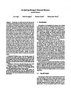
sense to separate processors from switching elements. A related model known as RMBM has been proposed by Thiruchelvan, Trahan, and Vaidyanathan [22]. This model also attempts to separate the I/O bandwidth from the processing power. A DMBC of size (n, m) is a rectangular array wherein the first row consists of full fledged processing elements and the rest of the rows comprise of switching elements. The rows are numbered 1 through m and the columns 1 through n. Think of the rows as broadcast buses. A row can be broken at any point using segment switches. There is a segment switch between any two columns in each row. These segment switches are locally controllable. Also, a processor can fuse the buses in any manner in its column. For example, processor i can fuse the first 10 buses in column i, in which case the first 10 rows will be connected in column i. In Figure 1, the fuse switches are indicated with triangles and the segment switches are indicated with boxes. At any time, a processor can read from a bus or write into a bus and connect appropriately all its (m) segment switches and (m − 1) fuse switches. See Figure 1.
B1 B2 B3 B4
M1
M2
M3
M4
M5
M6
M7
M8
P1
P2
P3
P4
P5
P6
P7
P8
.. .. .. .. .. .. .. .. .. .. .. .. ∆.... .. .. .. ∆.... .. .. .. ∆.... .. .. .. ..
.. .. .. .. .. .. .. .. .. .. .. .. ∆.... .. .. .. ∆.... .. .. .. ∆.... .. .. .. ..
.. .. .. .. .. .. .. .. .. .. .. .. ∆.... .. .. .. ∆.... .. .. .. ∆.... .. .. .. ..
.. .. .. .. .. .. .. .. .. .. .. .. ∆.... .. .. .. ∆.... .. .. .. ∆.... .. .. .. ..
.. .. .. .. .. .. .. .. .. .. .. .. ∆.... .. .. .. ∆.... .. .. .. ∆.... .. .. .. ..
.. .. .. .. .. .. .. .. .. .. .. .. ∆.... .. .. .. ∆.... .. .. .. ∆.... .. .. .. ..
.. .. .. .. .. .. .. .. .. .. .. .. ∆.... .. .. .. ∆.... .. .. .. ∆.... .. .. .. ..
.. .. .. .. .. .. .. .. .. .. .. .. ∆.... .. .. .. ∆.... .. .. .. ∆.... .. .. .. ..
Figure 1: A DMBC of Size (8,4) More details about the model can be found in [21]. Several fundamental algorithms for the DMBC were given in [21]. In this paper we consider the problems of sorting (both general keys and integer keys) and selection. The following results are supplied: 1) An algorithm to add n bits in O(1) time on an (n, n� ) DMBC, for any fixed � > 0. An algorithm on an (n, n) DMBC has been given in [21]; 2) 2
A randomized algorithm for sorting n integers in the range [1, n(log n)c ] (for any constant c > 0) on a DMBC ( logn n , n) that runs in time O(log n) with high probability. In contrast Thiruchelvan, Trahan, and Vaidyanathan [22] present a deterministic algorithm with a run time of O(log n log∗ n) on an RMBM of size ( log nnlog∗ n , n). 3) A sorting algorithm that can sort n numbers in O(1) time on a DMBC (n1+� , n) for any fixed � > 0. We show that this algorithm is optimal. The same algorithm also runs in time O(1) on a PRAM with reconfigurable buses of size (n1+� , nδ ), for any constants � > 0 and δ > 0. A description of this model can be found in [24]; and 4) A constant time randomized selection algorithm that employs an (n, n� ) DMBC. The rest of this paper is organized as follows: In section 2 we present some preliminaries. In section 3 we present our bit sum algorithm. Our integer sorting algorithm is presented in section 4. Sections 5 and 6 contain our sorting and selection algorithms. Section 7 concludes the paper.
2
Preliminaries
In this section we provide some preliminary facts and results that will be employed in the paper. � (n)) amount of any resource (like time, space, We say a randomized algorithm uses O(f etc.) if the amount of resource used is no more than cαf (n) with probability ≥ (1 − n−α ) � o�(.), etc. in a similar manner. for any α, c being a constant. We could also define Θ(.), By high probability we mean a probability of ≥ (1 − n−α ) for any constant α ≥ 1. Chernoff Bounds [5]. These bounds can be used to closely approximate the tail ends of a binomial distribution. A Bernoulli trial has two outcomes namely success and failure, the probability of success being p. A binomial distribution with parameters n and p, denoted as B(n, p), is the number of successes in n independent Bernoulli trials. Let X be a binomial random variable whose distribution is B(n, p). If m is any integer > np, then the following are true: P rob.[X > m] ≤
�
np m
�m
P rob.[X > (1 + δ)np] ≤ e−δ
em−np ; 2 np/3
P rob.[X < (1 − δ)np] ≤ e−δ for any 0 < δ < 1. 3
; and
2 np/2
A Sampling Lemma. Let Y be a sequence of n numbers from a linear order and let S = {k1 , k2, . . . , ks } be a random sample from Y . Also let k1� , k2� , . . . , ks� be the sorted order of this sample. If ri is the rank of ki� in Y , the following lemma provides a high probability confidence interval for ri . (The rank of any element k in Y is one plus the number of elements < k in Y .) �
Lemma 2.1 For every α, Prob. |ri − i ns | >
√
� √ 3α √ns log n < n−α .
A proof of the above lemma can be found in [19]. This lemma can be used to analyze many of the selection and sorting algorithms based on random sampling. Our selection algorithm makes use of random sampling.
3
Addition of n Bits
In this section we show that the addition of n bits can be performed on an (n, n� ) DMBC in O(1) time, for any constant � > 0. The following lemma has been proved by Sahni [21] for the DMBC. Similar results for the PARBUS was proven in [15]. Lemma 3.1 We can add n bits in a unit of time using a DMBC (3n, 2n). We can also add n bits in O(1) time using a DMBC (n, n). Our algorithm is based on a similar algorithm for the PARBUS model [11]. Like the algorithm of [11], we use several number systems in the algorithm. In the N1 system, any number 1 ≤ i ≤ n is represented using n processors as follows: If the processors are numbered from 1 through n, processor i will have a 1 and the rest of the processors will have a 0. In the N2 system, a subset of i processors have a 1 and the others have a 0. Evidently, both of these systems are unary.
3.1
Addition of Two Numbers
Now we prove that two numbers in unary can be added in constant time using an appropriate DMBC. Lemma 3.2 A number, say i, in N1 form and a number, say j, in N2 form can be added in O(1) time using a (4n + 1, 4n + 1) DMBC, when 0 ≤ i ≤ n and 0 ≤ j ≤ n.
4
0
1
1
0
1
0
1
(a)
Figure 2: Adding Two Numbers: An Example
Proof. The idea is to use bus dropping as in [11]. Assume that the number in N2 form is in the top row in every other column of the DMBC M. Every column that has a 0 in the top row, does not drop the bus whereas every column that has a 1 drops the bus by two rows. See Figure 2 for an example. In this example, i = 2 and j = 3. A 1 is written by the leftmost processor in bus 2i + 1. The figure shows only a portion of the machine M. In the right (not shown in the figure), there are 2n + 1 processors that will read buses 1, 3, 5, . . . respectively, one each. A unique processor will read the message 1 and this processor will know the sum of i and j. ✷ + 2, 2n + 1) in Lemma 3.3 A number i in N1 form can be divided by 2 using a DMBC ( 5n 2 O(1) time, when 0 ≤ i ≤ n. Proof. Switch connections for various rows and columns are made as follows: For any i and j (1 ≤ i ≤ n + 1 and 1 ≤ j ≤ n), the connection from the point (2i − 1, 2j − 1) to column 2j + 1 is a bus rising if i > j; otherwise the connection is straight . If i we have to compute the quotient of i/2 (i.e., 2 ), the leftmost processor writes a 1 in bus 2i + 1. There will be n2 + 1 right most read processors. These processors set their portions of the 2n + 1 buses in pass through mode and then read from buses 1, 3, 5, . . . , 2 n2 + 1. The unique processor that reads a 1 will have the correct result. See Figure 3 for an example. Clearly, the algorithm is correct. 5
0
1
2
3
4
5
6
7
1 2 3 4 5 6 7
(a)
Figure 3: Division by Two: An Example
3.2
Carry Look-Ahead Addition
In this section we show that n k-bit numbers whose sum is also a k-bit number can be added in O(1) time using a DMBC ((6.5n + 3)k, 4n + 1). The idea is to use carry look-ahead addition (CLA). CLA has been employed before by Jang and Prasanna on the RMESH [11]. But our implementation is different. Let the n numbers to be added be N1 , N2 , . . . , Nn . Ni in binary form is b1i b2i . . . bki , for i = 1, 2, . . . , n, where b1i is the least significant bit (LSB) and bki is the most significant bit (MSB). The machine will consist of k blocks each of size ((6.5n + 3), 4n + 1). The qth block � computes the sum of the carry from the previous stage (call it Cq ) and Sq = ni=1 bqi . The value of Sq is read off using 2n + 1 processors. Clearly, the final sum bit for the qth stage is the LSB of Sq + Cq . This is easily computed by the processor of the sum block that reads a bus signal. In the same block, the carry for the next stage (i.e., Cq+1 ) is computed using the division by 2 algorithm. Figure 4 depicts block q of the machine. Thus we have the following lemma: Lemma 3.4 The sum of n k-bit numbers can be computed in O(1) time on a DMBC ((6.5n+ 3)k, 4n + 1).
6
q
qth bits b i
Division by 2
SUM Cq
Cq+1 (2.5n+2) X (4n+1)
(4n+1) X (4n+1)
(a)
Figure 4: The qth Block of DMBC for CLA
3.3
Binary Bits to a Single Number Conversion
Here we consider the following problem: Say we have a q-bit binary number such that the bits are input on successive processors one bit per processor. We want to convert these bits into a single number and broadcast to every processor. This problem has applications in our main theorem. Lemma 3.5 The above problem of converting bits into a single number can be performed in O(1) time on a (q + 2q , 2q ) DMBC. Proof. Assume that the number is input in the first q processors so that the MSB is in processor 1 and so on. We make use of weighted bus dropping, i.e., processor i will drop the bus by 2q−i if the bit in this processor is 1; otherwise it will drop the bus by 0. A 1 is sent at the left top corner and there is a unique bus in the (q + 1)st column that will get a 1. This bus is identified using the standard trick of reading every bus. See Figure 5 for an example. ✷
3.4
The main Theorem
Finally, we prove the main result of this section, namely that the sum of n bits can be computed in O(1/�2) time using a DMBC (n, n� ), for any 1 > � > 0. The input is given to the top row (of processors) one bit per processor. The basic idea is to partition the DMBC into m × m submeshes (where m = n� ) and add the bits in n numbers to be each submesh in O(1) time using lemma 3.1. After this, there will be m 7
1 0
1 1
(a)
Figure 5: Binary to Single Conversion: An Example
added where each number is at most m. We group these numbers again with m numbers in each group and add the numbers in every group using lemma 3.4. We perform this task of grouping and adding until we have ≤ m numbers which can be added using lemma 3.4. More details follow. Step 1 Group the machine into DMBCs of size (n� , n� ). Let m = n� . Using lemma 3.1, we can add the m bits in each group in O(1) time. There will be 3 passes where in each pass we add m3 bits. The final sum is n numbers each with a single number. After this step, we will have m � �log n ≤ � log n + 1 bits. Step 2 Now partition the DMBC such that each part is a DMBC (m2 , m). There are m (log m + 1)-bit numbers to be added in each part. Add these numbers using lemma 3.4. According to lemma 3.4, this addition can be done in O(1) time on a DMBC ((6.5m + 3)(log m + 1), 4m + 1). But (6.5m + 3)(log m + 1) is ≤ m2 . Therefore, the same addition can also be done on an (m2 , m) DMBC in O(1) time. (There will be 4 passes where in each pass we add m4 numbers). 8
There is a crucial problem in this step. If we have to employ the CLA algorithm, the input should be such that all the LSBs are in the first block (see Figure 4); the next LSBs should be in the second block, and so on. But at the beginning of this step, each group of size (m, m) has a ≥ log m-bit number. In all there are ≥ m log m bits to be rearranged within a DMBC (m2 , m). Since the bisection is only m, we cannot afford to transport these numbers in bit form. We remedy this problem as follows: The m numbers of every DMBC (m2 , m) will be broadcast (not as bits but as whole numbers) along the m row buses, one per bus. Each processor reads the number it wants and also computes the bit it needs. Therefore, at the end of this step, we will have number has at most 2 log m + 1 bits.
n m2
numbers where each
Step 3 Convert the binary sum (which is in the form of bits in successive processors) of every (m2 , m) DMBC into a single number. This can be done using lemma 3.5 in O( logq m ) time, where q is the number of bits in the sum. The idea is to have logq m phases, where we convert log m bits of the sum into a single number. Finally, we will add the logq m numbers thus obtained (weighted appropriately). This number is broadcast to every processor in the DMBC (m2 , m). Step 4 Repeat steps 2 and 3 grouping m numbers each time. The group size will change appropriately. In the last step there will be m or less n ) bits each which can be added in O(1) time numbers of size O(log m using lemma 3.4. Clearly, the number of times step 2 will be executed is O( 1� ) and execution i takes O(i) time. Thus we get the following: Theorem 3.1 The sum of n bits can be computed in O( �12 ) time using a DMBC (n, n� ).
9
4
Integer Sorting
In this section we consider the problem of sorting n numbers where each number is an integer in the range [0, n(log n)c ] for any fixed c. The algorithm is randomized and runs in � time O(log n) on a DMBC ( logn n , n). We adopt the algorithm of Rajasekaran and Reif [20]. There are two basic ideas in the algorithm: 1) the radix sorting and 2) random sampling. Radix Sorting. The idea is captured by the following lemma (which applies to a variety of models including the PRAMs, PARBUS, DMBC, etc.): Lemma 4.1 If n numbers in the range [0, R] can be stable sorted using P processors in time T , then we can also stable sort n numbers in the range [0, Rc ] in O(T ) time using P processors, c being any constant.
Summary. A summary of [20]’s algorithm is as follows: There are two phases in the algorithm (called Coarse Sort and Fine Sort). In Coarse Sort, the n given numbers are sorted with respect to their log n − 3 log log n LSBs. This algorithm is a non-stable sort. Followed by Coarse Sort, the numbers are stable sorted with respect to the remaining bits. This step is called Fine Sort. (A sorting algorithm is said to be stable if equal keys remain in the same relative order in the output as they were in the input). We follow these phases in our adaptation also. Fine Sort. If the n given numbers are in the range [0, n(log n)c ], in this phase we are interested in sorting these n numbers with respect to their (c + 3) log log n MSBs. That is, we are interested in sorting n O(log log n)-bit numbers. An optimal algorithm for this problem has been given in [20]. A similar algorithm has been employed for the RMBM model [22]. The same algorithm when applied to the DMBC yields: Lemma 4.2 We can stable sort n O(log log n)-bit numbers on a ( logn n , n) DMBC in O(log n) time. � Coarse Sort. This algorithm sorts n numbers in the range [0, logn3 n ] in O(log n) time using n a DMBC ( log n , n). The sort is non-stable. The idea is to count how many keys are there in the input of a given value and use hashing to rearrange the keys according to their values. Let k1 , k2, . . . , kn be the n given keys. Let N(i) be the number of keys in the input whose
10
value is i, for 1 ≤ i ≤ logn3 n . Important steps in the algorithm are: 1) Randomly sample logn n keys from the input and sort this sample in O(log n) time using Cole’s algorithm; 2) In the sorted sample, we can determine how many keys are there of value i, 1 ≤ i ≤ logn3 n . If S(i) is the number of sample keys of value i, we obtain A(i)’s that are approximations to N(i)’s as follows. A(i) = d max{S(i) log n, log n} where d is a constant. A(i)’s thus obtained satisfy � [20]: a) A(i) ≥ N(i) for each i and b) i A(i) = O(n) with high probability; 3) Finally use hashing to rearrange the keys according to the sorted order. Implementation on the DMBC. We assume the CRCW version of the DMBC. In particular we assume the following: At any given time, more than one processor can try to write to the same bus in which case a random processor succeeds. Step 1 of the above algorithm can be performed on a ( logn n , n) DMBC in O(log n) time using Cole’s algorithm. Note that a DMBC (n, n) can simulate an n-processor O(n)-memory EREW PRAM retaining the time bound. In step 2, approximations to N(i)’s can be computed in O(1) time. In step 3, hashing is done as follows. We use a slightly different scheme than that has been employed in [20]. If a key kj is of value i, we say kj belongs to bucket i. Bucket i A(i) will be assigned � log successive processors. Processors are assigned in the order of bucket n values, i.e., processors of bucket 2 will follow processors for bucket 1; processors for bucket 3 will follow processors of bucket 2; and so on. Any key that belongs to bucket i will be hashed onto a random processor assigned to bucket i. To begin with, each processor π has log n keys that it has to hash onto other processors. At any given time processor π chooses a random remaining key kj and tries to write it in bus i� , where i� is the id of a random processor of the bucket that kj belongs to. If π succeeds in this attempt, it will eliminate kj from its queue and proceed with the remaining keys. If it does not, it will choose a random remaining key in the next step and proceed in a similar manner. It works until all its keys have been hashed onto appropriate processors. Also in every time step, each processor π will read from bus π and collect the key from the bus into its local queue. � n). The We claim that all the processors will complete their tasks within time O(log proof is as follows. Consider any bucket i. Let mi be the number of processors assigned to bucket i. This will mean that the number of keys in bucket i is ≤ mi log n with high probability. In step t of the algorithm, let nit be the number of keys of bucket i (from among � i all the processors) that have not yet been hashed onto. Let Nt = i nt . Nt i Then, the expected value of nt is n N(i). The expected number of remaining keys of
11
bucket i that will be chosen by their respective processors in time t is N (i) log n
nit n . log n Nt
That is, the
≤ mi . This in turn expected number of keys of bucket i that will be chosen in time t is means that the expected number of remaining keys of bucket i that will succeed in time t is N (i) ). Therefore, the expected number of keys (from among all buckets) that will succeed Ω( log n in time t is Ω( logn n ). Applying Chernoff bounds, the number of keys that will succeed in time t is Ω( logn n ) with high probability. Put together, all the processors will complete their � hashings within time O(log n). � After hashing has been completed, there will be O(log n) keys in each processor. We perform a prefix computation followed by a routing so that there will be exactly log n keys � n) in each processor. Prefix computation takes O(log n) time and the routing takes O(log time. Therefore we get the following theorem. � n) time provided the numbers Theorem 4.1 A DMBC ( logn n , n) can sort n numbers in O(log c are in the range [0, n(log n) ], c being any constant.
5
General Sorting
We consider the problem of sorting n general keys in this section. The input is assumed to be from a linear order and nothing else is assumed about the keys. Several optimal sequential algorithms have been designed for sorting which run in time O(n log n), n being the number of keys to be sorted (see e.g., [10]). Optimal parallel sorting algorithms are also known for several models of computing. For instance Cole’s algorithm runs in O(log n) time, given n EREW PRAM processors [6]. Since a DMBC (n, n) can simulate an n-processor O(n)-memory EREW PRAM, it follows that sorting can also be done in O(log n) time on an (n, n) DMBC. Thus we will focus our attention on the problem of constant time sorting on the DMBC. Fact 5.1 If sorting has to be performed in O(1) time on a DMBC, then the number of processors has to be Ω(n1+� ) for some constant � > 0. Also, the number of rows has to be Ω(n). Proof. The parallel comparison tree machine was introduced by Valiant in [23]. This model is similar to the sequential comparison tree model except that in every node of the parallel comparison tree, p pairs of comparisons (p being the number of processors) will be made and depending on the outcomes of these comparisons computation will branch to an appropriate 12
child. In this model one is charged only for the comparisons made and any other operation can be performed for free. Therefore, a parallel comparison tree can simulate a DMBC with the same number of processors. It then follows that any lower bound for sorting on the former will also hold on the latter. Any sorting algorithm that makes use of p parallel log n comparison tree processors will need Ω( log(1+ p ) time to sort n numbers [4]. This proves the ) n lower bound on the number of processors. The lower bound on the number of rows is proved using a bisection argument. Consider the permutation where the keys from the left half of the input have to be interchanged with keys from the right. In order to achieve this permutation in O(1) time, the bisection width has to be Ω(n). ✷ The following lemma due to Sahni [21] will be employed: Lemma 5.1 We can sort n numbers in O(1) time using an (n2 , n) DMBC. In this section we present an O(1) time optimal sorting algorithm, i.e., an algorithm that uses a DMBC (n1+� , n) for any fixed � > 0. This algorithm is based on the column sort algorithm of Leighton [14], which has been previously used for sorting on the PARBUS (see e.g. [2]). Let k1 , k2, . . . , kn be the n given numbers. These numbers are thought of as forming a matrix M with r = n2/3 rows and s = n1/3 columns. There are 7 steps in the algorithm: 1) Sort the columns in increasing order; 2) Transpose the matrix preserving the dimension as r × s. I.e., pick the elements in column major order and fill the rows in row major order; 3) Sort the columns in increasing order; 4) Rearrange the numbers applying the reverse of the permutation employed in step 2; 5) Sort the columns in a way that adjacent columns are sorted in reverse order; 6) Apply two steps of odd-even transposition sort to the rows; and 7) Sort each column in increasing order. At the end of step 7, it can be shown that, the numbers will be sorted in column major order. Implementation Details on DMBC. We will store the n given numbers in the first row of the DMBC with no more than one key per processor. At any given time each key will know which row and which column of the matrix M it belongs to. Whenever we need to sort the columns, we will make sure that the numbers belonging to the same column will be found in successive processors. On a DMBC (n, n), note that any permutation can be performed in O(1) time. This means that steps 2 and 4 can be performed in O(1) time. Step 6 can be performed in O(1) time as well as follows: Rearrange the numbers such that elements in the same row are in
13
successive processors and apply two steps of the odd-even transposition sort. After this, move the keys to where they came from. Next we describe how we implement steps 1,3,5, and 7. We first assume that we have a DMBC (n5/3 , n). Later we will indicate how to reduce the size to (n1+� , n) for any � > 0. Partition the DMBC into n1/3 parts each of size (n4/3 , n). Rearrange the n given numbers such that there are n2/3 numbers in each part located in the first n2/3 processors of each part. Think of each part as having a column of the matrix M. Now sort the numbers in each part (i.e., each column of M) using Sahni’s algorithm (see lemma 5.1). This can be done in O(1) time. This implies that steps 1,3,5, and 7 of column-sort can be performed in O(1) time. Therefore it follows that n numbers can be sorted in O(1) time on an (n5/3 , n) DMBC. We can reduce the size of DMBC to (n13/9 , n) as follows: Divide the n13/9 processors into n1/3 groups of size n10/9 each. We still use Leighton’s sort with r = n2/3 and s = n1/3 . In steps 1,3,5, and 7, n2/3 numbers are to be sorted using a DMBC (n10/9 , n). This is done using the DMBC algorithm above. In a similar way we can reduce the size to (n35/27 , n), (n97/81 , n), and so on. Thus we get the following theorem: Theorem 5.1 A DMBC (n1+� , n) can sort n numbers in O(1) time, � being any constant > 0. Sorting on a PRAM with Reconfigurable Buses. A PRAM with reconfigurable buses (call it PRAM-RB) of size (n, m) is nothing but a DMBC of size (n, m) where the n processing elements also have a shared common memory for communication. An integer sorting algorithm for this model has been given in [24]. Using the sort ideas in [21] and the bit sum algorithm of section 3, n numbers may be sorted on a PRAM-RB of size (n2 , nδ ) in O(1) time, for any fixed δ > 0, where the shared memory size is O(n). While the lower bound of Ω(n1+� ) on the number of processors holds on the PRAM-RB as well, the lower bound on the bisection width is no longer valid, since any permutation can now be realized in O(1) time using the shared memory. As a result, the above adaptation of Leighton’s sorting algorithm can be implemented on a PRAM-RB of size (n1+� , nδ ) for any fixed � > 0 and δ > 0. Hence we get the following: Theorem 5.2 Sorting of n numbers on the PRAM-RB of size (n1+� , nδ ) can be performed in O(1) time, for any constants � and δ greater than zero.
14
6
Selection
Given a sequence of n numbers k1 , k2, . . . , kn and an i ≤ n, the problem of selection is to identify the ith smallest of the n numbers. An elegant linear time sequential algorithm is known for selection (see e.g., [10]). Floyd and Rivest have given a simple linear time randomized algorithm for sequential selection [8]. Optimal parallel algorithms are also known for selection on various models of computing (see e.g., [17]). Most of the parallel selection algorithms (both deterministic and randomized) make use of the technique of sampling. � time on a DMBC (n, n� ) for In this section we show that selection can be done in O(1) any fixed � > 0. The basic idea is the following: 1) Pick a random sample S of size q = o(n); 2) Choose two elements &1 and &2 from the sample whose ranks in S are i nq − δ and i nq + δ for some appropriate δ. One can show that these elements ‘bracket’ the element to be selected with high probability; 3) Eliminate all keys whose values are outside the range [&1 , &2 ]; 4) Perform an appropriate selection from out of the remaining keys. We implement the above scheme on the CRCW version of the DMBC. In particular we assume the following: At any given time, more than one processor can try to write to the same bus in which case one of them succeeds and we don’t know which one. More details follow. We assume a DMBC (n, n). It is easy to reduce the size to (n, n� ) for any fixed � > 0. Algorithm Select Step 1 Each key decides to include itself in the sample S with probability � √n) keys in the sample. will be Θ(
√1 . n
There
Step 2 Concentrate the sample keys in the first n3/4 processors. This is done as follows. Every sample key chooses a random processor in the range [1, n3/4 ] and tries to write in the corresponding bus. If it does not succeed in one attempt it will make more attempts until it succeeds. Step 3 Sort the numbers in the first n3/4 processors using Theorem 5.1. Processors which do not get a sample key will have a key valued ∞. Let q be the number of keys � � √ iq in the sample. Choose keys &1 and &2 from S with ranks n − d q log n and � � √ √ iq � + d q log n, respectively, d being a constant > 3α. This takes O(1) time. n 15
Step 4 Eliminate keys that fall outside the range [&1 , &2 ]. Count the number, s, of sur� √n log n). viving keys. It can be shown that this number is O( Step 5 Count the number del of keys deleted that are < &1 . If the key to be selected is not one of the remaining keys (i.e., if del ≥ i or i > del + s), start all over again (i.e., go to step 1). Step 6 Concentrate the surviving keys in the first n3/4 processors just like in step 2. Sort the first n3/4 processors and output the (i − del)th smallest key from out of the remaining keys. � time on an (n, n) CRCW DMBC. Theorem 6.1 The above algorithm runs in O(1)
Proof. Step 1 takes O(1) time. The number of keys in the sample S is B(n, √1n ). Using � √n). In step 2, the probability that a key does not get Chernoff bounds, this number is Θ( √ n concentrated in a single attempt is O( n3/4 ). This implies that the probability of failure in −α−1 ). Thus this concentration step terminates in time 4(α + 1) successive attempts is O(n � O(1). Step 3 takes O(1) time in accordance with Theorem 5.1. Counting in steps 4 and 5 can be performed in time O(1) as well (cf. lemma 3.1). In step 6, the concentration task can be � time. Sorting analyzed along the same lines as that of step 2 to realize that it takes O(1) takes O(1) time (cf. Theorem 5.1). ✷ The following Theorem is easy to prove now: � time on a DMBC of size (n, n� ), for any Theorem 6.2 Selection can be performed in O(1) fixed � > 0.
Proof. The only modifications needed in the algorithm are: 1) In step 1 every key includes 1 so that the number of keys in the sample will be itself in the sample with probability n1−�/2 �/2 � Θ(n ). 2) In step 2, we concentrate the keys in the first n� processors. Counting in steps 4 and 5 can be done using lemma 3.1. ✷
16
7
Conclusions
In this paper we have presented efficient algorithms for sorting and selection on the DMBC. We have considered both integer sorting and general sorting problems. An interesting open problem is to obtain a matching deterministic selection algorithm. Also, it is not clear if we need n� rows in order to perform selection. However the processor bound of our selection algorithm is optimal. Also it is an open problem to reduce the processor bound of our O(1) time sorting algorithm when applied to integers. For example, if we have to sort n bits, we could do so in O(1) time on a DMBC (n, n� ), for any fixed � > 0 (cf. lemma 3.1).
References [1] P. Beame and J. Hastad, Optimal Bounds for Decision Problems on the CRCW PRAM, Journal of the ACM, 36(3), 1989, pp. 643-670. [2] Y. Ben-Asher, D. Peleg, R. Ramaswami, and A. Schuster, The Power of Reconfiguration, Journal of Parallel and Distributed Computing, 1991, pp. 139-153. [3] S.H. Bokhari, Finding Maximum on an array processor with a global bus, IEEE Trans. Computers 33, 1984, pp. 133-139. [4] R. Bopanna, A Lower Bound for Sorting on the Parallel Comparison Tree, Information Processing Letters, 1989. [5] H. Chernoff, A Measure of Asymptotic Efficiency for Tests of a Hypothesis Based on the Sum of Observations, Annals of Mathematical Statistics 2, 1952, pp. 241-256. [6] R. Cole, Parallel Merge Sort, SIAM Journal on Computing, 17, 1989, pp. 770-785. [7] T.H. Cormen, C.E. Leiserson, and R.L. Rivest, Introduction to Algorithms, The MIT Press, 1990. [8] R.W. Floyd, and R.L. Rivest, Expected Time Bounds for Selection, Communications of the ACM, Vol. 18, No.3, 1975, pp. 165-172. [9] E. Hao, P.D. McKenzie and Q.F. Stout, Selection on the Reconfigurable Mesh, Proc. Frontiers of Massively Parallel Computation, 1992. [10] E. Horowitz and S. Sahni, Fundamentals of Computer Algorithms, Computer Science Press, 1978. 17
[11] J. Jang, H. Park, and V.K. Prasanna, A Fast Algorithm for Computing Histograms on a Reconfigurable Mesh, Proc. Frontiers of Massively Parallel Computing, 1992, pp. 244-251. [12] J. Jang and V.K. Prasanna, An Optimal Sorting Algorithm on Reconfigurable Mesh, Proc. International Parallel Processing Symposium, 1992, pp. 130-137. [13] J. Jenq and S. Sahni, Reconfigurable Mesh Algorithms for Image Shrinking, Expanding, Clustering, and Template Matching, Proc. International Parallel Processing Symposium, 1991, pp. 208-215. [14] T. Leighton, Tight Bounds on the Complexity of Parallel Sorting, IEEE Transactions on Computers, C-34(4), 1985, pp. 344-354. [15] R. Miller, V.K. Prasanna-Kumar, D. Reisis, and Q.F. Stout, Parallel Computations on Reconfigurable Meshes, IEEE Transactions on Computers, 1993. [16] M. Nigam and S. Sahni, Sorting n Numbers on n×n Reconfigurable Meshes with Buses, Proc. International Parallel Processing Symposium, 1993, pp. 174-181. [17] S. Rajasekaran, Sorting and Selection on Interconnection Networks, DIMACS Series in Discrete Mathematics and Theoretical Computer Science 21, 1995, pp. 275-296. [18] S. Rajasekaran, Mesh Connected Computers with Fixed and Reconfigurable Buses: Packet Routing, Sorting, and Selection, Proc. First Annual European Symposium on Algorithms, Oct. 1993. Springer-Verlag Lecture Notes in Computer Science 726, 1993, pp. 272-283. [19] S. Rajasekaran and J.H. Reif, Derivation of Randomized Sorting and Selection Algorithms, in Parallel Algorithm Derivation and Program Transformation, Edited by R. Paige, J.H. Reif, and R. Wachter, Kluwer Academic Publishers, 1993, pp. 187-205. [20] S. Rajasekaran and J.H. Reif, Optimal and Sublogarithmic Time Randomized Parallel Sorting Algorithms, SIAM Journal on Computing 18, 1989, pp. 594-607. [21] S. Sahni, Data Manipulation on the Distributed Memory Bus Computer, to appear in Parallel Processing Letters, 1995. [22] R.K. Thiruchelvan, J.L. Trahan, and R. Vaidyanathan, Sorting on Reconfigurable Multiple Bus Machines, Proc. International Parallel Processing Symposium, 1994. 18
[23] L.G. Valiant, Parallelism in Comparison Problems, SIAM Journal of Computing, vol. 4, 1975, pp. 348–355. [24] R. Vaidyanathan, Sorting on PRAMs with Reconfigurable Buses, Information Processing Letters 42, 1994, pp. 203-208.
19