SPAMMS: A Sensor-based Pipeline Autonomous Monitoring and Maintenance System Jong-Hoon Kim‡ , Gokarna Sharma‡ , Noureddine Boudriga§ , and S. Sitharama Iyengar‡ ‡ Department
of Computer Science Louisiana State University, Baton Rouge, Louisiana 70803, USA Email:
[email protected], {gokarna, iyengar}@csc.lsu.edu § CN & S Research Lab, School of Communication Engineering University of Carthage, 2083 Ariana, Tunisia Email:
[email protected]
Abstract—Pipeline-based applications have become the indispensable part of life. Active monitoring and frequent inspections are critical to maintaining pipeline health. However, these tasks are highly expensive using the traditional maintenance systems, knowing that the pipeline systems can be largely deployed in an inaccessible and hazardous environment. In this paper, we propose a novel cost effective, scalable, customizable, and autonomous sensor-based system, called SPAMMS. It combines robot agent based technologies with sensing technologies for efficiently locating health related events and allows active and corrective monitoring and maintenance of the pipelines. SPAMMS integrates RFID systems with mobile sensors and autonomous robots. While the mobile sensor motion is based on the fluid transported by the pipeline, the fixed sensors provide event and mobile sensor location information and contribute efficiently to the study of health history of the pipeline. In addition, it permits a good tracking of the mobile sensors. Using the output of event analysis, a robot agent gets command from the controlling system, travels inside the pipelines for detailed inspection and repairing of the reported incidents (e.g., damage, leakage, or corrosion). The key innovations of SPAMMS are 3-fold: (a) the system can apply to a large variety of pipeline systems; (b) the solution provided is cost effective since it uses low cost powerless fixed sensors that can be setup while the pipeline system is operating; (c) the robot is autonomous and the localization technique allows controllable errors. The simulation experiments described in this paper along with prototyping activities demonstrate the feasibility of SPAMMS.
I. I NTRODUCTION Gas, oil, water, and sewer pipelines have become the indispensable part of life. Active monitoring and frequent inspections are critical to maintaining pipeline health. Hence, the continuous active monitoring and maintenance system for these pipelines is essential, however, deployment, monitoring, and maintenance of them should remain cost effective, scalable, and easily customizable. There are a number of technologies to monitor, control, and maintain gas, oil, water, and sewer pipelines. Most of these technologies rely on some kind of communication networks to transfer data collected from inside and outside of the pipelines to the control stations. Different network architectures have been used to provide reliable communication in pipeline systems [1], [2], [3] and attempted to support pipeline monitoring. These architectures can be based on wired networks, wireless c 2010 IEEE 978-1-4244-5489-1/10/ $26.00
networks, or may set up a combination of wired and wireless networks. These architectures are primarily based on major reliability factors, say the connectivity of the network, the continuity of power supply, and the maintainability of the network [2]. Since the pipeline network extends generally in a line, it is important for the network to be continuously connected to collect and transfer information from the sensor nodes distributed over the pipeline to the control station and also to transfer control commands to the actor and sensor nodes, which are often located inside the pipeline. Moreover, power supply continuity is a critical feature for the pipeline to be able to operate properly. Power is needed not only to operate the network but also to operate the sensors and actor nodes. Lastly, network maintainability should also be performed, as faults in the network or in the nodes can occur at any time for different reasons. Pipeline monitoring systems should provide mechanisms to quickly and seamlessly recover from faults and report problems and their locations to the control station(s) to be handled. Nowadays, most of the pipeline monitoring systems are based on wired networks to connect and communicate with pipeline sensors. A number of problems can be noticed for the monitoring systems using wired networks [2], [3]. Three major problems can be mentioned. Firstly, any damage in any part of the wires of the network may significantly degrade the performance of the pipeline monitoring system. Secondly, the physical security of such systems cannot be achieved when the pipeline expands on large areas. Lastly, since most of the pipelines that carry gas, oil, water, or sewer are located underground or in zones difficult to reach, it is hard to locate faults and repair them. This makes the process of maintaining a faulty network a very complex task. One of the possible solutions of the aforementioned problems is to use redundant networks and provide fault tolerance [3]. However, this solution may not be sufficient to support high bandwidth, in the case of large instant information is collected, and guarantee radio communication continuity. In addition, this solution does consider the duplication of sensors, in case of failure. Ad hoc and sensor networks is an area of research which is rapidly growing due to the development of inexpensive sensing technologies. Sensor networks are gaining attention in a large
variety of applications including environmental monitoring, ecology, agriculture, robotics, military, and health care. They can also be used in the protection and monitoring of critical pipeline infrastructures carrying oil, gas, water, sewage, and many other chemicals. Advancements in sensor technology have made possible the automated real-time monitoring of the health of the pipeline systems. A number of sensor network based technologies have been designed to monitor pipelines and to provide remote facilities to detect and report the positions of any leakage, damage, or corrosion [2], [4], [5], [6], [7]. One can notice, however, that these systems are passive in the way that they only report on incidents and do not contribute to their repairing. On the other side, a number of robotic agent based technologies to monitor pipelines and maintain them from damage has also been developed in literature [8], [9]. These technologies are designed to detect and locate any leakage, damage, or corrosion. While a huge number of robot based systems have been proposed that are manually controlled, a few number have considered semi-autonomous/autonomous solutions. Based on these observations, we believe that a monitoring system for pipelines should combine sensor technologies, which are well suited for event localization, and robotic techniques, which allow active and corrective monitoring. In addition, we believe that a more efficient technique for locating objects and incidents should be integrated in such systems. In this paper, we aim at designing a cost effective pipeline maintenance and monitoring system. Such a system would allow frequent inspection, early detection of problems, targeted recovery measures, and precise localization. To this end, we propose SPAMMS, a novel method which combines sensor technologies and robotic techniques for efficient event localization and active and corrective monitoring of any kind of pipelines. Our solution will integrate RFID systems as fixed sensors with mobile sensors and topology-aware robots. In this paper, we make the following contributions for the efficient and cost effective pipeline monitoring and maintenance: • We show the feasibility of using MICA based mobile sensors with attached RFID reader/writers and different sensing functions in pipeline monitoring and maintenance by analyzing their potential applications in pipeline systems. • We propose a RFID systems based localization technique, which functions correctively in any kind of pipelines and environment with controllable errors. The experiments based on the simulation confirm viability of the use of such RFID systems. • We design a prototype model of an autonomous, topology-aware robot agent by integrating different sensing functions and actuators to perform detailed inspection and react to the detected incidents for corrective monitoring. • We show the cost effectiveness and scalability of using sensor networks and robot agent based technologies in active and corrective monitoring of pipelines carrying
different materials such as gas, oil, water, or sewer. The rest of the paper is organized as follows: Section II provides state of the art on the development of sensor networks and robotic agent based pipeline monitoring and maintenance systems and their various limitations. Section III discusses the requirements for the efficient pipeline monitoring and maintenance system. In addition, it discusses the high level overview of the newly developed sensor-based pipeline autonomous monitoring and maintenance system, SPAMMS. Section IV describes the architecture of SPAMMS system and its components: RFIDs, mobile sensors, and robotic agents in detail. The implementation and evaluation of the proposed system is given in section V and VI. Section VII concludes the paper. II. S TATE OF THE A RT A number of sensor network based technologies to monitor pipelines to transfer sensed information collected from the pipelines has been studied in literature [2], [4], [5], [6], [7]. These technologies are designed to provide remote facilities to detect and to report the positions of any leakage, damage, or corrosion. One can notice, however, that these systems are passive in the way that they only report on incidents and do not contribute to their repairing. The following three major works we describe share this limitation. Jawhar et al. [1] and Mohamed and Jawhar [2] presented an architectural model based on sensor networks that can be used to provide pipeline monitoring and control functions. These papers provide discussions and recommendations concerning issues and challenges in the protection and monitoring of the critical and essential infrastructures of pipelines carrying oil, gas, water, and other important resources and proposed a faulttolerant sensor network architecture for monitoring pipeline infrastructures. This architecture is an integrated wired and wireless network, where the wireless part is used as a backup to collect detected events from sensor nodes when there is any failure in the wired network. This architecture only solves some of the reliability issues of wired networks for pipelines monitoring and control. In addition to the aforementioned drawback, one can notice that the solution does not include a model providing an optimized management of the energy assigned to sensor nodes. In particular, nodes close to the control station will consume more power than other nodes due to heavy packet routing. Jin and Eydgahi [5] developed a sensor network platform for pipeline system monitoring using active sensing devices such as Lead Zirconate Titanate (PZT) sensors for simultaneous actuation and sensing to detect, localize, and quantify fluid bursts, leakages, and other anomalies. The existence of multiple propagation modes and the dispersive nature of the modes in such kind of guided waves propagation makes sensing, communication, and control difficult to address. This paper assumes that a set of sensors are mounted on the curve of the pipeline for generating and measuring guided waves that propagate along the pipeline. Since this solution is based on the transmission and the detection of lamb waves and uses
TABLE I: Comparison of various pipeline monitoring techniques Quality on Localization Project
Active/ Passive
Sensing Mode
Use of Robot
Method
Efficiency
Cost
Autonomy
Capability of Repairing
Jawhar et al. [1] Jin and Edygahi [5] PipeNet [7] Murphy et al. [4] PipeProbe [10] SewerSnort [6] KANTARO [8] MAKRO [9] Our Solution
passive passive passive active active active active active active
static static static mobile mobile mobile mobile mobile mobile
no no no no no no yes yes yes
Wired Sensor Networks signal triangulation signal cross-correlation RF-based quorum signal beacons + interpolation RSSI-based beacons robot wheel rotations sewer blueprint based RFID systems
low (subject to failure) fair (sometime complicated) fair (not error-free) low (depends on detection) low (limited beacons) fair (subject to drifter speed) low (many slip errors) fair (map may not available) high
high high high high high high N/A N/A low
no no no yes no yes yes yes yes
no no no limited no no no no controllable
simple triangulation methods based on time-of-arrival, several drawbacks can be noticed. First, the sensors are customized for a specific task and are pre-deployed on the pipeline, making the solution inappropriate for other types of pipeline technologies. Second, the topology of the pipeline is made very simple, making the location technique inefficient for more complex pipeline topologies. PipeNet [7] collects hydraulic and acoustic/vibration data at high sampling rates. It also provides algorithms to analyze this data to detect and locate leaks. A wired network is set up to collect events and control the sensors and allowing every sensor to monitor its local leak status signal and adapting existing algorithms for leak detection and localization via cross-correlation of acoustic/vibration signals. In addition to the drawbacks mentioned for the second work, one can highlight the fact that uniformity of the liquid characteristics is important for the efficiency of the location computation. Several solutions have been made available to monitor pipelines using mobile sensors. The basic idea in these solutions is to use drifting sensors to monitor the pipeline, the liquid flowing in the pipeline, and different chemicals generated inside the pipeline; let the moving sensors inspect the monitored objects; and finally collect these data (through beacons, for example). The localization of incidents may experience some inefficiencies due to the lack of control of the sensor’s mobility or the constraints on the network costs. Several other limitations can be observed as shown by the following three important works. Murphy et al. [4] developed a wireless network system (WSN) for a team of underwater Collaborative Autonomous Agents (CAAs) that are capable of locating and repairing scale formations in tanks and pipes within inaccessible environments. The hardware is small but it includes some functionalities and wireless communications for detecting scale formation in oil pipelines. The repair actuator, a device that can treat the calcium carbonate site with a repair fluid/chemical, is also embedded with in CAAs, which treats scale formation once it is detected and located by the agent. However, there are still a number of problems for manual repairing to locate the defect
at the time when the repair actuator failed to handle because one can notice that scale formation is not only the problem someone can observe in pipelines. Nevertheless, CAAs do not have efficient localization ability to contribute for manual repairing for those general problems except scale formations. Chang et al. [10] proposed PipeProbe, a mobile sensor system for mapping water pipelines hidden inside cement walls or under floor coverings. It works by dropping a tiny sensor capsule into the source of the water pipelines and gathers accelerometer and water pressure readings. But it has more focus on sensor system for mapping indoor water pipelines with other applications. If capsule size is the same as pipeline, 3D accelerometer information will be stable but it can not turn in elbows or tee pipe fittings. Thus, the capsule has to be small enough to make turn at those fittings, then when that capsule is flowing along the pipeline, it will vibrate and then vibration produces noisy 3D accelerometer readings which are difficult to post-process. Kim et al. [6] proposed SewerSnort, a low cost, unmanned, fully automated in-sewer gas monitoring system. A floating sensor is introduced at the upstream station and drifts to the end pumping station, collecting location tagged gas measurements. The retrieved data from SewerSnort provides a gas exposure profile to be used for preventive maintenance and/or repair. But, it is very difficult to model and fit sensors appropriately due to the large spatio-temporal variability of sewer pipelines. While their model based on gas measurements, it can not be applied to other pipeline systems like water which has no such properties. In addition, one can notice that the floating sensor’s ability to measure the gas exposure is also based on measuring flow levels and detecting leaks and dumps in the pipeline because these incidents may reduce the gas concentration in the vicinity of their locations drastically. On the other side, a number of robot agent based technologies to monitor pipelines and maintain them from damage has also been developed in literature [8], [9]. These technologies are designed to detect and locate any leakage, damage, or corrosion. While a huge number of robot based systems have been proposed that are manually controlled, a
few number have considered semi-autonomous/autonomous solutions. KANTARO [8] is a prototype of a fully autonomous mobile robot designed for Φ200 to Φ300mm sewer pipeline inspection. It is a simple moving mechanism which reduces resource usage and occupies limited space for control purposes. Despite the resource and space optimization, the techniques developed for KANTARO to compute its location experience some drawbacks due to the limitations of the approximation methods it uses based on robot wheel rotations. In fact a wheel slip will induce errors on the location computation. To overcome these drawbacks, the use of image processing to detect the position of manholes, inlets, and pipe joints along with blueprint of the pipeline was proposed. The efficiency of this solution is, therefore, highly dependent on the density of the pictured objects and the availability of blueprints. Another robotic agent studied in the literature is MAKRO [9]. MAKRO is also one of the prototypes of a fully autonomous, untethered, multi-segmented, self-steering articulated robot platform. It is designed for autonomous navigation in roughly cleaned, non-man-entry sewer pipes within a diameter range of Φ300 to Φ600mm at dry weather conditions. A modular approach used to construct MAKRO gives some advantages to this solution, since it allows to add various equipments by attaching segments. However, MAKRO experiences the same localization drawbacks mentioned for KANTARO, since MAKRO’s navigation system relies on sewer maps which may not be always available. In addition, some assumptions (e.g., dried pipeline) made for the operation of the robot make it inappropriate to provide real-time operation [11]. The characteristics of various pipeline monitoring techniques are summarized in Table I. III. SPAMMS S YSTEM OVERVIEW A. System Requirements for an Efficient Monitoring System Pipelines have been a part of our constructions for a long time. They need to be maintained regularly. However, maintenance costs keep increasing, as well as scale of pipelines. Thus, cost effectiveness and scalability are becoming the major concern in building pipeline monitoring and maintenance systems. In particular, a pipeline monitoring and maintenance system should perform two main activities: first, it inspects pipeline health and reports, regularly, incidents to the control station(s), second, it helps recovering the system health from any leakage, damage, or corrosion. We have seen in the previous section that different network architectures and monitoring techniques have been proposed for pipeline monitoring and maintenance systems. However, these systems suffer from various limitations. A cost effective and scalable pipeline monitoring and maintenance system should be able to comply with the following requirements: • The system should provide active monitoring and recovery actions: The pipeline monitoring and maintenance system should be able to find any defects in the unhealthy pipeline under monitoring before any failure happens. It should be able to properly analyze the incidents and provide recovery reaction.
•
•
•
•
•
The system should be cost effective: The system should lower the deployment, operational, and maintenance cost of pipeline monitoring and maintenance. There are three specific requirements to achieve cost effectiveness. Firstly, sensors used for detecting and locating any leakage, damage, or corrosion should be general purpose, achieve multiple inspection, have small dimensions, and use low power so that the cost of sensors will be reduced. Secondly, sensors should have no complex computation capabilities which reduces the need of complex software, but they should be capable enough to transfer and receive necessary data. Lastly, simple physical actions, if needed, should be performed by the fully autonomous topologyaware robot agent. The system should be easily customizable: With minimal activity and modification, it should be a general solution to cope with different applications, such as monitoring the health of a large variety of pipeline types, and allow the integration of sophisticated general purpose sensors. The system should be scalable: Since most of the gas, water, oil, or sewer pipelines spread over thousands of kilometers, the system should work for any length of the pipeline and any extent from the access point because all current methods are limited to small travel distance from their access point. The system should also be independent of pipeline characteristics (e.g., shape, size, material) and topology. The system should be dynamic. In other words, the system should include capabilities and softwares allowing dynamic inspection of the pipeline, react to the problems when they are detected and located, and be autonomous for robust performance. The system should implement efficient localization techniques: Efficiency, requires that entities involved in the inspection and incidents discovered within the pipeline should be located with reasonable errors.
B. High Level Description of SPAMMS In the previous subsection, we identified the requirements for cost effective and scalable pipeline monitoring and maintenance system. The proposed system should provide active monitoring and recovery actions. At the same time, it should be dynamic, easily customizable, and provide efficient localization techniques for the incidents to properly locate and perform necessary actions. To this end, we propose a system for active monitoring and maintenance of pipelines, denoted by SPAMMS. It is a novel method which combines sensing and robot-based activity technologies for a corrective monitoring and efficient localization of events for pipelines. Our system primarily consists of three main components: fixed sensors (FSs), mobile sensors (MSs), and autonomous robot agents (RAs). Our system integrates fixed sensors with mobile sensors and autonomous robot agents for identifying and reporting the incidents, and efficient event localization. In addition to an efficient localization method, our system appears to be cost effective; in the sense that: (a) it uses very low cost RFID
systems; (b) it uses a limited number of mobile sensors, in active monitoring, which are relatively cheap; (3) it reduces the zones where the robot agent is requested to operate. This would allow frequent inspection, early detection of problems, and targeted recovery measures. The first component of SPAMMS is composed by a set of fixed powerless sensors implemented by RFID (Radio Frequency IDentification) systems. RFID tags do not require manual inspection or optical scanning, and are inexpensive, pushing toward $0.05 per tag. They are used to provide mobile sensors with location information within the pipeline topology. Notice that RFIDs are used to help controlling pipeline health, in the way similar to their use in healthcare, as studied in [12], [13]. In SPAMMS, we choose to use RFID sensors which guide mobile sensors for the location information. To achieve effective localization, SPAMMS assumes that a scalable set of RFID systems is integrated inside the pipeline in a way that they are uniformly distributed and the distance separating RFID neighbors be controlled by the errors acceptable for an effective localization (for example, one can install an RFID every 50 cm in a linear pipeline). The installation of RFIDs can be made initially (at the construction of the pipeline) or when needed by the pipeline operation. In the latter case, the robot will be controlled to set up the needed RFIDs. As RFIDs are very inexpensive and need no power, they can be very close to each other. The information stored in an RFID can be read by any mobile sensor or robot agent in the vicinity of that RFID. RFIDs can also record history information provided by the active components of SPAMMS. The history information built on an RFID can be post-processed by the controlling system after their collection using the active components. The information on an RFID also includes useful data for event localization. These data can be of different types and formats and can be reduced to the ID of the RFID. The detailed description of RFID sensors is given in Section IV. The second component of SPAMMS is composed by a limited set of mobile sensors. The mobile sensors are deployed at strategic locations by analyzing the available geo-spatial information of the pipelines and the inspection demands. The dispensing schedule of mobile sensors can be configured based on some application scenarios. For instance, if the operators want to understand how the properties of pipelines changes over time, they can float mobile sensors at regular intervals for continuous sampling. Therefore, once a mobile sensor is deployed in a pipeline under service, the fluid transported by the pipeline will provide sensor mobility. The mobile sensor is generally equipped with different kinds of inspection capabilities for pipeline inspection purposes. Those capabilities, when attached to the mobile sensor, allows it to play different roles simultaneously, including CCD sensing, chemical sensing, pressure sensing, and sonar sensing. The selection of specific sensor functions that will be attached to a mobile sensor is determined by the material carried by the pipeline and the nature of the inspection. In addition to
the basic sensing functions, the mobile sensor integrates two important functions, localizing its position and communicating with the other components. A first implementation of the mobile sensors is based on MICA1 system motes and allows a modular architecture integrating an RFID reader and writer for reading and writing RFID tags. The main advantage of SPAMMS mobile sensors is their immunity to pipe profile. They are neither sensitive to the pipeline materials nor dependent on the shapes of the pipelines. The mobile sensors can also operate during low flow rate conditions. The fluid flow in pipe can either be laminar (i.e., a stable and streamlined flow) or turbulent (i.e., a highly irregular and random motion). More detailed description of different functional sensors attached to the mobile sensors is given in next section. The third component of SPAMMS is the robot agent, which aims at being topology-aware and fully autonomous. It is equipped with different kind of actuators for repairing pipeline damages depending on the inspection and repair demands. It is completely mobile in the sense that it can cope with the topology of the pipeline, which can be non planar. It is able to repair the pipeline incidents after they have been identified and located with the help of RFIDs and mobile sensors. Repairing functions attached to a robot agent can be of two types: they can be mechanical (such as drilling or grinding,) or chemical (such as spraying air, water, or chemicals). An RFID reader and writer is also integrated in the robot. Our robot has four essential features. The first and foremost feature is its mobility, which enables it to travel in any spatial conditions of the pipeline (e.g., horizontal and vertical) involving with any kind of pipeline fittings (T-shapes, Y-shapes and elbows), using four caterpillars and an extendable link system. Secondly, the operating architecture being used is very simple, flexible and adaptable enough for the inspection environment being considered. Thirdly, it has flexible extension interface for physical actions which enables it to equip with various different mechanical and chemical devices, such as robotic arms or chemical sprayers. Lastly, it is comprised of a powerful tracking system for handling navigational complications both efficiently as well as autonomously. The robot agent used in SPAMMS is the extended version of the robot agent FAMPER, proposed in [14], [15]. The controlling system controls the robot through inspection and repair commands after it analyze the data that was collected from mobile sensors. When the robot agent gets command from the controlling system, it travels inside the pipelines for detailed inspection and repairing the incident (e.g., damage, leakage, or corrosion) located with the help of RFID and mobile sensors inspection. It is able to stop and even reverse motion in the pipeline for in-depth, close inspection of detected incidents. In conclusion, the non-destructive testing technologies designed for sensors and robotic agents can potentially be utilized for better characterization and analysis of pipeline defects, corrosion, or damage. The robotic arm associated with the robot agent can also be used to install fixed sensors
TABLE II: RFID tag control structure 1 bit
15 bits
RCB
BCB
TABLE III: RFID tag history structure 1 byte
2 bytes
MSID
TS
Fig. 1: SPAMMS monitoring and maintenance scenario TABLE IV: RFID tag event structure within the pipeline, while manual installation is not feasible. In this sense, the robot agent can function as a setup agent of fixed sensors inside the pipeline, inspection agent for detailed inspection in the area where mobile sensor located for problems, and recovery agent to recover the pipeline from the problems using its recovery mechanisms. Figure 1 depicts an application of SPAMMS. IV. SPAMMS S YSTEM D ESIGN RFID, most often means an RF Barcode. An RFID system consists of two primary components - a tag and a reader. RFID tags, which are the wireless barcode labels applied to objects, are usually attached to a tracking object; a reader is then used to track tagged objects. At its simplest form, a tag is a beacon announcing its presence to a reader. When a RFID reader integrated with mobile sensor emits carrier signal, the RFID tag eventually charges up and it clocks out the data associated with it, and the reader sees modulated data, which is called envelope detection. In addition, a RFID tag has an antenna that emits radio signals to activate the tag and read/write data to it. Many RFID implements collision detection/resolution mechanism and allows multiple tags to be queried in the same area. While sensor network is used to sense and monitor physical, chemical, and biological environments through sensing of sound, temperature, light, and etc., RFID tags allow any objects to be trackable or sensible as long as a RFID tag can be attached. RFID tag capabilities, however, extend well beyond a simple beacon. Tag can hold a unique identity (UID) of 8 bytes in length and can be used for inventory management at global scale. More than just an UID, a tag can carry re-writable persistent storage which is accessible via a reader. In this sense, RFID tags can extend a sensor network by providing sensing/sensible property to otherwise un-sensible objects, thus provide the last-hop connection of a sensor network. In SPAMMS, RFIDs work as fixed sensors. The RFID tags are integrated inside the pipeline with reasonable interval between two immediate neighbors, while RFID reader/writers are integrated in mobile sensors and robot agents which read and write RFID tags available in their course of operation for recording the events related to their sensing activities, collecting the history of events stored on intermediate fixed sensors, and cleaning, when needed, the content of the fixed sensor. The RFID tags used in SPAMMS are passive in the sense that they have no battery of their own and make
1 byte
2 bytes
4 bits
4 bits
1 byte
FSID
TS
Eloc
Etype
Einfo
use of the incoming radio waves broadcast by reader/writers (integrated in mobile sensors or robot agent) to power their response. In addition to the history information related to sensing, the re-writable persistent storage available in RFID tags is used to store useful information related to the motion of mobile sensors and can help, therefore, locating mobile sensors, in trapping situations. The limited persistent storage capacity (of the order of 256 bytes) of each RFID tag used in SPAMMS is divided into three types of areas to allow the storage of the data structures for the management of the necessary information for pipeline monitoring and maintenance and the mobile sensor tracking. In addition to the data identifying the RFID unit, the data and control structures used by SPAMMS for a RFID tag are given in Table II, III, and IV. The data structure given in Table II is used for controlling the data that need to be read/written from RFID tags. The major fields of this control structure are: (a) a redundancy check bit (RCB), which is used to determine all the blocks available in the RFID tag are empty or not; and (b) 15 block control bits (BCB), which are used to determine whether the data available in the respective blocks can be read/written. The data structure given in Table III is used to store history information of mobile sensors passed through RFID tags location. The major fields of this data structure are: (a) the mobile sensor ID (MSID), which identifies the mobile sensor that already crossed the location of the RFID tag; and (b) the time stamp (TS), which determines the instant of passing the RFID tag location. The data structure given in Table IV is used to store event information. The major fields occurring in this data structure include: (a) the RFID ID (FSID), which identifies the fixed sensor handling the persistent storage; (b) the time stamp (TS), which determines the instant of an event storage in the RFID; (c) the event location (Eloc), which contains the number of RFID-segments separating the event location and the event storage; and (d) the event type (Etype) and event information (Einfo), which report on the incidents detected. RFID readers employ tag-reading algorithms that are capable of identifying hundreds of tags per second. Once a tag is identified, a reader may read data from this tag or write to it.
Fig. 2: Side view of the stretchable caterpillar
Memory management in RFID tags is handled considering the following different situations: Managing memory full condition: If the memory entries of the RFID tag in the vicinity of the mobile sensor are full, then the data is stored in the next available RFID tag, provided that the distance to the available tag can be reported in field Eloc (in our case the distance is smaller than 16). When a certain number (say, half the distance, for example) of tags within that distance are found full, then the mobile sensor, needing to store a detected event, has to randomly select a tag (within the distance), delete its oldest entry and store its event report. Initializing the monitoring process: When the process of inspecting the pipeline starts, the first mobile sensor to be inserted in the system will be in charge of reading the content of the tags it encounters and deleting all entries they contain with BCB=1, and stores its identity in the mobile sensor tracking area. The deletion operation can be subject to some criteria, when needed. In particular, when there is a need to keep the information related to the inspection realized during a time close to the current time, the deletion will be performed on the data having a time stamp prior to this period. Entry duplication: To cope with the limited space in the RFIDs, adding an event at a given time is subject to the absence of report on this event made by another mobile sensor in time instant sufficiently close to the current time. Tracking mobile sensors: to provide tracking capabilities, every mobile sensor is required to register its identity, along with a time stamp, on the RFID tags they come close to. However, a selection criterion may be applied during registration. In particular, registration can be operated on only selected tags, based on density-aware selection criteria (for example registration can be made every 5 tags). On the other hand, the first design we present here for mobile sensors is based on MICA motes. MICA is a commercially available product that has been used widely by researchers and developers. It provides a large variety of the typical features of a mote. It also uses an Atmel ATmega 128L processor running at 4 megahertz. The 128L is an 8bit micro-controller that has 128 kilobytes of onboard flash memory to store the mote’s program. This CPU is limited but complies with the needs of a large set of pipeline related applications. The design of a more sophisticated and modular mobile sensor architecture is ongoing at the Robotics Research
Fig. 3: Sectional view of the robot agent
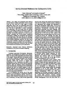
Laboratory (LSU, Louisiana). The prospected architecture will provide more computational power and larger storage memory and more flexible interfaces for generic sensing functions. In addition to some sensing functions provided by MICA, two functions have been added. The first functions allows the mobile sensor to read the content of RFIDs and write to the RFIDs reports related to the events they collect and the time stamps of passage close to the RFIDs. A reasonable size of storage space is provided to copy all the histories found on the tags they encounter on their route. The analysis of histories is performed by the analysis center(s) as soon as the mobile sensor gets out of the pipeline. The second function allows the mobile sensor to perform a limited intelligence to clean, drop, and write events and verify criteria. In addition, a buoy device is built to protect the equipments of a mobile sensor during motion and to allow floating. The robot agent we have designed for SPAMMS is a fully autonomous topology-aware robot, in the sense that (a) it carries all required modules for accessing any pipeline region; (b) it runs a control program for navigation and incident analysis; and (c) it reacts to incidents using on-board resources. The robot agent has four caterpillars which are segmented to three parts: front, middle, and end frame. The front and end frame link to middle frame in each side as depicted in Figure 2, can be bendable by maximum of 60 degrees and have 30 degrees fork which enhances flexibility in turning and crossing obstacles, and provides self-adjust positioning of the robot to overcome motion singularity problem [16]. The middle frame has four shrinkable shafts which provide support for the caterpillar frame. The caterpillar frame is also shrinkable by 50% the length of its shrinkable caterpillar shaft, giving the robot the flexibility to use in inspecting pipelines of variable sizes. For example, if total length of the shaft is 40mm, caterpillar frame can be shrinkable by 20mm in maximum, as shown in Figure 3. The outside circle is actual pipeline and dotted one is its maximum size after shrinking. Those shrinkable and bendable frames enable the robot agent
to travel vertically as well as horizontally in pipelines with different fittings. The robot agent tries to cope with three challenges: mechanical, electrical, and reactive. To address mechanical challenges, the robot implements horizontal and vertical mobility. Thank to its four 3-segment caterpillars, the robot is able to flexibly bend, change directions (up to 90 degree), and climb. To address the second challenge, we made the electrical part of the robot water-proof including sensing activity, processing power, and memory management. To address the third challenge, the design of the robot has included space and processing for two types of reactive actions to incidents. For chemical incidents, the robot is equipped with chemical sprayer; while it can integrate a robotic arm to react on physical incidents. In the following section a first prototype has been built including a chemical sprayer. Based on the monitoring application using SPAMMS, some sophisticated inspection-related functions can be added to the robot. In particular, an ultrasonic device can be designed to check the health of the pipeline.
Fig. 4: A prototype of MICA1 based mobile sensor with attached RFID reader/writer and different sensing functions
V. I MPLEMENTATION A prototype has been built at the Robotic Research Laboratory (LSU, Louisiana) complying with the design issues presented in the previous section. The objective of the prototype is to validate various aspects we introduced in the design process. For the sake of efficiency, we have delayed the implementation of a few functions, including the segmented and bendable caterpillar track and advanced sensing functions. The prototype includes three components: (a) an EM4001ISObased RFID system; (b) a MICA1-based mobile sensor; and (c) a 1-segment caterpillar robot integrating sensing functions and tag reading capability. The prototype provided for the mobile sensor is depicted in Figure 4. It implements a MICA1-based device integrated within two types of containers, a capsule type and a spherical type. The container protects the device and provides floating capabilities. The overall dimension of the container does not exceed a diameter of 50mm. The device contains one processor equipped with a communication module, one tag reader, and two sensing functions, light and sound sensors. The device also allows a few extensions to add appropriate modules. The prototype for the robot agent (depicted in Figure 5b) has 4 extendable one-segment caterpillars, which allow horizontal and vertical mobility and change directions. It commands differentiated and controllable speeds for the caterpillars. The robot has attached an RFID reader/writer to collect information stored at the tag level, a chemical tank and sprayer for actuation purposes, two Li-ion batteries for one hour life, and a CCD camera for creating high-quality, low-noise images related to inspection. The robot prototype is designed to have high processing power, large memory, and several sensing functions. In addition, the robot has four extendable external interfaces to add different modules for pipeline inspection demands as shown in Figure 3. The pipeline topology that was used for the implementation of the autonomous topology-aware robot is given in Figure
Fig. 6: Illustration of a pipeline system used in experiments
5a. This topology comprises linear segments, horizontal and vertical L-bends to demonstrate the capability of the robot to cope with such environment. The pipeline used in the topology is a 150mm sewer pipeline to which an RFID tag is attached every 500mm. A robot mission is illustrated by Figures 5c and 5d, where the robot performs horizontal motion and a vertical motion within the pipeline, respectively. VI. E XPERIMENTS To validate the performance of SPAMMS several experiments have been conducted. The objective of the simulation is, first, to analyze the tag information size over time and inspections and, second, to compare the efficiency of SPAMMS with respect to a system that does not use mobile sensors with RFID systems. The illustration of the pipeline system used in SPAMMS simulation is given in Figure 6. It consists of 26 pipeline segments, one upstream station, and one end pumping station. We assume that the fluid carried by the pipeline is flowing in the direction as indicated by the arrows. We also assume that RFID tags have limited capacity (only 50 entries) to store history and incident information during the pipeline inspection. The mobile sensors are drifted to the pipeline from the upstream station and the motion to them is provided by the fluid transported through the pipeline. The drifted mobile sensors are collected for incident localization and further processing at the end pumping station. The incidents are created randomly at different locations to simulate the actual pipeline environment. In the experiments related to the tag occupation size, we
(a) A pipeline topology
(b) A robot agent
(c) Robot performing horizontal motion
(d) Robot performing vertical motion
Fig. 5: Illustration of a pipeline topology and a prototype robot mission 50
H=1, s/s=5, Hop=6 H=5, s/s=5, Hop=6 H=10, s/s=5, Hop=6
45
Average occupation
40 35 30 25 20 15 10 5 0
0
20
40 60 Number of mobile sensors
80
100
Fig. 7: Average occupation on persistent storage of RFID tags in different history settings 50 45 40
Average occupation
first derive the optimal values for the number of fixed sensors that should be installed per segment of the pipeline (denoted by s/s), number of inspection history information that can be accommodated (denoted by H), the number of mobile sensors (denoted by n), and the number of hops (denoted by Hop) that are optimal to store the incidents information as soon as they are detected. The number of hops is measured in terms of the number of successive RFID tags located after the incident location the detected incident is stored. In order to estimate optimal values of s/s, H, n, and Hop, we derived an algorithm to measure the characteristics of mobile sensors while they are drifting inside the pipeline. When mobile sensors reached to the joints they choose to flow randomly to either horizontal or vertical direction with the expected value of 1/2. When mobile sensors pass through the RFID tags in each segment, they randomly choose two RFID tags available in that segment and write their identity information, which provide the tracking information for all mobile sensors passed through that particular segment. Fixed sensors (or tags) attached inside the pipeline provide localization for the mobile sensors and robot agents by sharing their location information. The fixed sensors store the history information of mobile sensors and help the robot agents finding incidents reported by mobile sensors. We assume the mobile sensors to report on their motion to tags randomly selected per segment. When the memory of a given tag is full, the oldest entry is deleted from the tag and the recent identity information is inserted. If the incident is detected during inspection and the memory entries of the RFID tag in the vicinity of the mobile sensor which detected the incident are full, then the data is stored in the next available RFID tag, provided that the distance to the available tag can be reported in the field Eloc (in our experiments the distance is 6) of the RFID event structure. In the experiments, we implemented that the mobile sensor tries to write in the first available RFID tag until Hop/2. After Hop/2, it randomly selects a tag based on some random number generator and stores on the tag provided that it is with in the remaining distance by deleting its oldest entry. Figure 7 and 8 show the average occupation of messages in the limited persistent storage of RFID tags. They show that the load of the tags increases with the number of histories (H) and number of mobile sensors (n). In addition, we
H=10, H=10, H=20, H=20,
s/s=10, s/s=20, s/s=10, s/s=20,
10
20
Hop=6 Hop=6 Hop=6 Hop=6
35 30 25 20 15 10 5 0
0
30 40 50 60 70 Number of mobile sensors
80
90
100
Fig. 8: Average occupation on persistent storage of RFID tags in different history and fixed sensors/segment settings
notice that for a given number of mobile sensors the tag load increases significantly with H and decreases with the number of sensors/segment (s/s). This shows the trade-off between the load and the product of H and s/s. Figure 9 shows the 3D graph depicting the load of all RFID tags when 12 incidents are randomly generated and 20 mobile sensors are used assuming that H = 5, s/s = 10, and Hop = 6. The figure demonstrates that the RFID tags located just after the incidents have higher load and that the following RFID tags have the load decreasing with the distance separating them from the incident. The second set of experiments aimed at comparing the hop
RFID tag entries
60 40 20 0 30 25
30 20 20
15 10 Y‐axis of the pipeline layout
R EFERENCES
10
5 0
0
X‐axis of the pipeline layout
Fig. 9: Measured RFID entries concentration for 12 incidents with n = 20, H=5, s/s= 10, and Hop = 6 350
Shortest path Depth first Random walk
Average hop distance
300 250 200 150 100 50 0
0
1
2
3
agent based technologies for efficiently locating health related events and allows active and corrective monitoring and maintenance of any kind of pipeline systems. Experiments along with the prototyping activities for mobile sensors and robot agent with powerless RFIDs based on the prototype pipeline system demonstrate the feasibility of SPAMMS, its cost effectiveness and its scalability. More detailed examination of the faulttolerant information storage in RFID systems and effects of the fluid speed in mobile sensors and robot agents remain as a future work.
4 5 6 7 8 9 10 11 12 13 14 15 16 17 18 19 20 Hopecount from the upstream station
Fig. 10: Comparing robot hop distance for three schemes
distances (in terms of the number of segments traveled from the upstream station) made by the robot to find the reported incidents in three cases: (a) the robot is aware of the incidents position (as provided by our system); (b) the robot applies depth first strategy to locate the incident; and (c) the robot attempts random walk. To achieve significant comparison the random walk is repeated several times (1000000 random samplings) and the distance computed is the average hop distance traveled. The distance reported for the depth firstbased strategy is also the average of the distances needed to realize to reach all incidents located at the same hop count with respect to the upstream station. Figure 10 depicts the hop distance comparison for a grid pipeline having 10 per 10 segments. We can notice that our approach gives the least hop distance to perform (since the graph is the bisector of the first quadrant). The other two methods compute an average hop distance that is very high compared to our method and that the former hop distances increase significantly with the location of the segment where the incident occurs. VII. C ONCLUSION In this paper, we proposed a novel cost effective, scalable, customizable, and autonomous sensor-based system, called SPAMMS, which combines sensing technologies with robot
[1] I. Jawhar, N. Mohamed, and K. Shuaib, “A framework for pipeline infrastructure monitoring using wireless sensor networks,” in Wireless Telecommunications Symposium, 2007. WTS 2007, April 2007, pp. 1–7. [2] N. Mohamed and I. Jawhar, “A fault tolerant wired/wireless sensor network architecture for monitoring pipeline infrastructures,” in SENSORCOMM ’08: Proceedings of the 2008 Second International Conference on Sensor Technologies and Applications. Washington, DC, USA: IEEE Computer Society, 2008, pp. 179–184. [3] N. Mohamed, I. Jawhar, and K. Shuaib, “Reliability challenges and enhancement approaches for pipeline sensor and actor networks,” in ICWN, 2008, pp. 46–51. [4] F. Murphy, D. Laffey, B. O’Flynn, J. Buckley, and J. Barton, “Development of a wireless sensor network for collaborative agents to treat scale formation in oil pipes,” in EWSN, 2007, pp. 179–194. [5] Y. Jin and A. Eydgahi, “Monitoring of distributed pipeline systems by wireless sensor networks,” in Proceedings of The 2008 IJAC-IJME International Conference, Nashville, TN, USA, 2008. [6] J. Kim, J. S. Lim, J. Friedman, U. Lee, L. Vieira, D. Rosso, M. Gerla, and M. B. Srivastava, “Sewersnort: A drifting sensor for in-situ sewer gas monitoring,” In Sixth Annual IEEE Communications Society Conference on Sensor, Mesh and Ad Hoc Communications and Networks (SECON 2009), 2009. [7] I. Stoianov, L. Nachman, S. Madden, and T. Tokmouline, “PIPENET: a wireless sensor network for pipeline monitoring,” in IPSN ’07: Proceedings of the 6th international conference on Information processing in sensor networks. New York, NY, USA: ACM, 2007, pp. 264–273. [8] A. Nassiraei, Y. Kawamura, A. Ahrary, Y. Mikuriya, and K. Ishii, “Concept and design of a fully autonomous sewer pipe inspection mobile robot “KANTARO”,” in Robotics and Automation, 2007 IEEE International Conference on, April 2007, pp. 136–143. [9] K.-U. Scholl, V. Kepplin, K. Berns, and R. Dillmann, “Controlling a multi-joint robot for autonomous sewer inspection,” in Robotics and Automation, 2000. Proceedings. ICRA ’00. IEEE International Conference on, vol. 2, 2000, pp. 1701–1706 vol.2. [10] Y.-C. Chang, T.-T. Lai, H.-H. Chu, and P. Huang, “Pipeprobe: Mapping spatial layout of indoor water pipelines,” Mobile Data Management, IEEE International Conference on, vol. 0, pp. 391–392, 2009. [11] E. Rome, J. Hertzberg, F. Kirchner, U. Licht, and T. Christaller, “Towards autonomous sewer robots: the MAKRO project,” Urban Water, vol. 1, pp. 57–70(14), March 1999. [12] L. Ho, M. Moh, Z. Walker, T. Hamada, and C.-F. Su, “A prototype on RFID and sensor networks for elder healthcare: progress report,” in E-WIND ’05: Proceedings of the 2005 ACM SIGCOMM workshop on Experimental approaches to wireless network design and analysis. New York, NY, USA: ACM, 2005, pp. 70–75. [13] F. Hu, L. Celentano, and Y. Xiao, “Error-resistant RFID-assisted wireless sensor networks for cardiac telehealthcare,” Wireless Communications and Mobile Computing, vol. 9, no. 1, pp. 85–101, 2009. [14] J.-H. Kim, “Design of a fully autonomous mobile pipeline exploration robot (FAMPER),” Master’s thesis, 2008. [Online]. Available: http://etd.lsu.edu/docs/available/etd-11112008-121037/ [15] J.-H. Kim, G. Sharma, and S. S. Iyengar, “FAMPER: A fully autonomous mobile robot for pipeline exploration,” in IEEE-ICIT 2010 International Conference on Industrial Technology. IEEE, March, 2010, Accepted. [16] Y. S. Kwon, H. Lim, E.-J. Jung, and B.-J. Yi, “Design and motion planning of a two-moduled indoor pipeline inspection robot,” in ICRA, 2008, pp. 3998–4004.