Larry Carter2. Jeanne Ferrante2 ...... Larry Carter received his Ph.D. in Mathematics from .... Garey, M. R., Johnson, D. S., and Stockmeyer, L. 1976. Some.
1
SPARSE TILING FOR STATIONARY ITERATIVE METHODS
Michelle Mills Strout1 2 Larry Carter Jeanne Ferrante2 3 Barbara Kreaseck Abstract In modern computers, a program’s data locality can affect performance significantly. This paper details full sparse tiling, a run-time reordering transformation that improves the data locality for stationary iterative methods such as Gauss–Seidel operating on sparse matrices. In scientific applications such as finite element analysis, these iterative methods dominate the execution time. Full sparse tiling chooses a permutation of the rows and columns of the sparse matrix, and then an order of execution that achieves better data locality. We prove that full sparsetiled Gauss–Seidel generates a solution that is bitwise identical to traditional Gauss–Seidel on the permuted matrix. We also present measurements of the performance improvements and the overheads of full sparse tiling and of cache blocking for irregular grids, a related technique developed by Douglas et al. Key words: tiling, iterative alogorithms, static and dynamic analysis, irregular grids, data locality, sparse matrix, computer architecture
The International Journal of High Performance Computing Applications, Volume 18, No. 1, Spring 2004,pp. 95–113 DOI: 10.1177/1094342004041294 © 2004 Sage Publications
Introduction
In almost all modern computers, whenever a memory location is referenced by a program, the data in the referenced location and nearby locations are brought into a 1 fast but small data cache. Any additional references to data before these are evicted from the cache will be one or two orders of magnitude faster than references to main (DRAM) memory. A program is said to have good data locality if, most of the time, the computer finds the data referenced by the program in its cache. The locality of a program can be improved by changing the order of computation and/or the assignment of data to memory locations so that references to the same or nearby locations occur near to each other in time during the execution of the program. This paper presents full sparse tiling, a run-time reordering transformation which improves the data locality and consequently the performance of stationary iterative methods operating on sparse matrices. In scientific applications, such as finite element analysis (FEA), these iterative methods dominate the execution time. FEA is a numerical technique for solving partial differential equations in scientific applications such as stress analysis, heat transfer, and fluid flow. In FEA the physical domain is modeled with a discretized irregular grid or mesh. FEA generates simultaneous linear equations that describe the relationship between the unknowns at each node in the mesh. Typical unknowns include displacement, temperature, and pressure. These equations are represented as a systems of simultaneous linear equations → → → A u = f , where u is a vector→ of unknowns, A is a sparse matrix of coefficients, and f is a vector of known constants. Stationary iterative methods such as Gauss–Seidel (GS), successive overrelaxation (SOR), and Jacobi are used to solve systems of simultaneous linear equations (Barrett et al., 1994). These methods solve for the → unknown vector u by iteratively applying an approximate inverse for the matrix A, converging toward a solution. The algorithm for GS is shown in equation (1) with → uv representing an element in the vector u , fv an element → in the vector f , and avw the element at row v and column w in the square matrix A. We refer to each of the T iterations of the outermost loop as a convergence iteration. The v loop iterates over the R unknowns and corresponding rows in matrix A. The w loop, which is implicit in the summations, iterates over the R columns of matrix A. Note that the first summation uses values of uw that were computed earlier in the current convergence iteration, 1
ARGONNE NATIONAL LABORATORY
2
UNIVERSITY OF CALIFORNIA, SAN DIEGO
3
LA SIERRA UNIVERSITY
TILING FOR STATIONARY METHODS
95
while the second uses values computed in the previous convergence iteration. Upon the completion of each convergence iteration a new value has been generated for all → the unknowns in u . for iter = 1, 2, …, T for v = 0, 1, …, (R – 1) R–1 v–1 § · a vw u w – a vw u w¸ (1) uv = ( 1 ⁄ a vv ) ¨ f v – © ¹ w=0 w = v+1
¦
¦
In many applications, fewer than 1% of the possible entries of the matrix are non-zeros (Pugh and Shpeisman, 1998; Im, 2000). A sparse matrix format saves computation time and storage, because only the non-zero entries of the matrix are stored and traversed within the computation. Figure 1, which is discussed further in Section 2, shows how GS can be implemented using the compressed sparse row (CSR) format displayed in Figure 2. In the implementation of GS of Figure 1, there are opportunities to improve the data locality within a convergence iteration (intra-iteration locality) and between convergence iterations (inter-iteration locality). The order in which elements of the unknown vector are visited and stored will affect intra-iteration locality. The typical schedule for GS, as shown in Figure 1, completes all the computation for one convergence iteration before doing any computation for the next.→ Because the unknown → vector u , right-hand side vector f , and sparse matrix A are often quite large, it is very unlikely that inter-iteration locality occurs in a typical GS implementation. Compile-time-only transformations such as traditional tiling (Wolfe, 1987; Irigoin and Triolet, 1988; Gannon et al., 1988; Wolfe, 1989; Wolf and Lam, 1991; Carr and Kennedy, 1992; McKinley et al., 1996) are not applicable because the structure of the sparse matrix and therefore the resulting memory reference patterns into the u ′ array are typically not available until run-time. More precisely, use of the CSR index arrays ia and ja to reference into the u ′ array (see Figure 1) result in non-affine memory references which can only be analyzed at run-time. This can be accomplished by using an inspector/executor strategy (Mirchandaney et al., 1988; Das et al., 1994). A run-time inspector calculates a reordering of the computation (iterations of the loop) and the data (elements in the unknown vector and associated rows and columns in the matrix). The executor then performs the computation using the new orderings. Cache blocking for irregular grids (Douglas et al., 2000) and full sparse tiling (Strout et al., 2001) are two such run-time reordering transformations developed for the stationary iterative method GS. We refer to both these transformations as sparse tiling transformations because their executor has been transformed from the original
96
COMPUTING APPLICATIONS
GAUSSSEIDELCSR(A ′ (ia, ja, a), u′ , f′ ) for iter = 1, T do for i = 0,(R – 1) do 1: u′ [i] = f ′ [i] for p = ia[i], ia[i + 1] – 1 do if (ja[p] ≠ i) then 2: u′ [i]=u′ [i] – a[p] * u ′ [ja[p]] else 3: diag[i]=a[p] endif endfor 4: u′ [i]=u ′ [i]/diag[i] endfor endfor Fig. 1 (CSR).
Gauss–Seidel for compressed sparse row
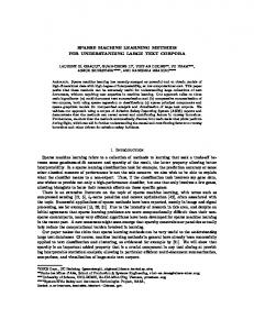
code to one that executes the iteration space in a tile-bytile fashion. Each tile contains computations from multiple convergence iterations for a subset of the unknowns. Since sparse matrix data structures are involved, the actual mapping of iteration points to tiles is done at runtime. To illustrate sparse tiling transformations, we first visualize the GS computation for a sample sparse matrix. The non-zero structure of a sparse matrix represents the → relationships between the unknowns in vector u . In a matrix graph G(V, E), there is a node v ∈ V for each unknown u v and an edge < v, w > ∈ E for each non-zero in the sparse matrix A. The GS computation on a sample sparse matrix can be visualized with the iteration space graph in Figure 3 where each convergence iteration is represented by a copy of the matrix graph. Although the sample matrix graph is two-dimensional (2D), sparse tiling transformations can handle any square sparse matrix. Each iteration point2, < iter, v >, represents the computations for u v at convergence iteration iter as specified in equation (1). A data dependence, represented by an arrow, occurs when one iteration point computes a value that is used in another iteration point. For clarity, only the data dependences for the iteration points associated with one matrix node are shown in the figure. In GS, each computation for u v uses the most recently calculated values of the neighboring unknowns; therefore some data dependences come from iteration points in the same convergence iteration, and some come from points in the previous convergence iteration. Figure 4 illustrates how sparse tiles are created with cache blocking (Douglas et al., 2000). Figure 5 exhibits a full sparse tiling of the same sample GS iteration space. For both these transformations, the code is transformed so that a run-time generated schedule is executed. Specif-
Fig. 2
Compressed sparse row (CSR) format.
Fig. 4 Fig. 3 Example irregular Gauss–Seidel iteration space graph for 3 convergence iterations.
ically, the schedule changes from sweeping over the entire sparse matrix each convergence iteration to executing the computation tile-by-tile. The new schedule using sparse tiles improves inter-iteration and intra-iteration locality and thereby improves performance (Strout et al., 2001). While it is possible to use sparse tiling to improve the performance of GS on a parallel computer (Strout et al., 2002), this paper focuses on the legality and performance of serially-executed schedules.
Cache-blocked Gauss–Seidel.
Sections 2 and 3 provide an overview of the inspector/ executor framework for implementing both sparse tiling transformations and present the proof of correctness for full sparse tiling. Then, in Section 4 we describe experiments on a variety of machines that investigate the issues involved in selecting parameters for both sparse tiling transformations, a comparison of the performance improvements observed in the executors, and the overhead of the inspectors. Finally, we describe how full sparse tiling can be applied to other stationary iterative methods, present related work, and conclude.
TILING FOR STATIONARY METHODS
97
Fig. 5
2
Full sparse-tiled Gauss–Seidel.
The Sparse Tiling Executor
Inspector/executor strategies were initially developed for parallelizing applications with irregular memory references (Das et al., 1994). For sparse tiling, the inspector examines the non-zero structure of the sparse matrix at run-time, generates a data reordering and a schedule based on a tiling function, and remaps the sparse matrix and vectors based on the data reordering. The executor is a transformed version of the original code that uses the remapped matrix and vectors and the schedule created by the inspector. In this section, we describe how GS for the CSR format is transformed at compile time to generate the sparse tiling executor. Theorem 1 in Section 2.3 constrains the tiling function so that a serial tile-by-tile schedule generates an unknown vector that is bit-equivalent to what is generated from a typical GS schedule that uses the same data ordering. The algorithms used by the sparse tiling inspector and the proof that they satisfy the constraints given in Theorem 1 are detailed in Section 3. The original order, v = 0, 1, …, (R – 1) given to the unknowns and corresponding matrix rows and columns is often arbitrary and can be changed without affecting the convergence properties of GS (Wu, 1990). Therefore, if the unknowns are mapped to another order before performing GS, the final numerical result will vary somewhat, but the GS convergence properties still hold. Since full sparse tiling (and cache blocking) perform an initial reordering of the unknowns, to prove correctness of sparse-tiled GS we compare the result of sparse-tiled GS using the generated reordering, i = σ(v) where i is the loop iterator in Figures 1 and 6, to that of typical GS using the same reordering. Therefore, in Figures 1 and 6, → assume that the original matrix A, unknown vector u , and → right-hand side f have been remapped using the reorder-
98
COMPUTING APPLICATIONS
ing function i = σ(v) such that A′σ ( v )σ ( w ) = A vw , u′σ ( v ) = u v , and f σ′ ( v ) = f v . Figure 1 gives detailed pseudo-code for typical GS written for the CSR matrix format. Using CSR, the nonzeros in the sparse matrix A′ are stored by row using three one-dimensional arrays ia, ja, and a (see Figure 2). The non-zeros of the ith row of A′ are stored in the a array, from locations ia [i] up to ia [i + 1] – 1. The corresponding entries of ja indicate→the non-zero’s column. In → Figure 1, the vectors u′ and f ′ are represented with the arrays u′ and f ′ . At run-time, sparse tiling inspectors generate a data reordering function, σ(v) : V → { 0, …, ( R – 1 ) } and a tiling function, θ(iter, v) : { 1, …, T } × V → {0, …, (k – 1)}. The tiling function maps iteration points < iter, v > to tiles. From this tiling function, the inspector creates a schedule function, sched(titleID, iter): {0, …, (k – 1)} × { 1, …, T } → 2 { 0, …, ( R – 1 ) }. The schedule function specifies for each tile and convergence iteration the subset of the reordered unknowns that must be updated. The transformed code shown in Figure 6 performs a tile-by-tile execution of the iteration points using the schedule function, which is created by the inspector to satisfy the following: sched ( tileID, iter ) = { σ ( v )
θ ( iter, v ) = tileID }.
To prove the correctness of the sparse-tiled GS in Figure 6, we first determine the symbolic data dependence relations for the GS pseudo-code shown in Figure 1. We then specify the compile-time mappings (Kelly and Pugh, 1995) that transform typical GS for CSR to sparsetiled GS for CSR. Finally, we determine the constraints that the run-time generated tiling function θ, and corresponding schedule function sched, must satisfy to make the transformation legal. A transformation is legal if the transformed data dependences are satisfied by a lexicographical execution of the transformed iteration space. 2.1 DATA DEPENDENCE RELATIONS IN GS FOR CSR Each statement exists within an iteration space defined by the surrounding loops. For example, Statement 1 in Figure 1 lies within the iteration space {[iter, i] | (1 ≤ iter ≤ T) and (0 ≤ i ≤ R)}. Data dependences indicate when an instance of a statement must execute before the instance of another (possibly the same) statement to preserve the program’s semantics. In our context, data dependence relations are sets of data dependences between statement instances (Kelly and Pugh, 1995) expressed as mappings. For example, since Statement 1 in Figure 1 writes to the same memory location at each convergence iterations iter, there is a dependence between any instance of Statement 1 to all later instances
GAUSSSEIDELCSR_ST(A ′ (ia, ja, a), u ′ , f ′ , sched, k) for tileID = 0,(k – 1) do for iter = 1, T do for i ∈ sched(tileID,iter) 1: u ′ [i] = f′ [i] for p = ia[i], ia[i+1] – 1 do if (ja[p] ≠ i) then 2: u ′ [i] = u ′ [i] – a[p] * u ′ [ja[p]] else 3: diag[i] = a[p] endif endfor 4: u ′ [i]=u ′ [i]/diag[i] endfor endfor endfor
Fig. 6
Serial execution of sparse-tiled Gauss–Seidel for compressed sparse row (CSR).
of Statement 1. These dependences can be specified with the following data dependence relation: { [ iter 1, i ] → [ iter 2, i ] and
1 ≤ iter 1 < iter 2 ≤ T
0 ≤ i < R }.
By using uninterpreted function symbols, it is possible to represent the data dependence relations between indirect memory references as well (Pugh and Wonnacott, 1994). The values in the index arrays ia and ja are not known until run-time, therefore we represent those values abstractly with the uninterpreted function symbols ia() and ja(). For example, the dependence relation between the write of u′ [i] in Statement 1 of Figure 1 and the read of u′ [ ja [ p]] in Statement 2 is as follows: { [ iter 1, i ] → [ iter 2, i, p ]
1 ≤ iter 1 ≤ iter 2 ≤ T
and 0 ≤ i < R and ia ( i ) ≤ p < ia ( i + 1 ) and i ≠ ja ( p ) }. The full list of data dependence relations for the code in Figure 1 is in Strout (2003). 2.2 COMPILE-TIME TRANSFORMATION MAPPINGS The sparse-tiled GS code in Figure 6 executes points in the iteration space {[iter, i] | (1 ≤ iter ≤ T) and (0 ≤ i < R)} in a tile-by-tile fashion. To generate the sparse-tiled GS executor, the code in Figure 1 is transformed to a unified iteration space that includes a tiling loop. Ahmed et
al. (2000a) and Kelly and Pugh (1995) give two different methods for building a unified iteration space. In this dissertation, we use the Kelly–Pugh method. In a unified iteration space, each loop that a statement resides within corresponds to a pair of dimensions, where the first dimension of the pair is a value of the index variable, and the second dimension is the numerical order of the enclosed loop or statement. For Figure 6, the unified iteration space can be described as follows: { [ tileID, 1, iter, 1, i, 1, 1, 1 ] ( 1 ≤ iter ≤ T ) and ( 0 ≤ i < R ) } ∪ { [ tileID, 1, iter, 1, i, 2, p, s ] ( 1 ≤ iter ≤ T ) and ( 0 ≤ i < R ) and ia ( i ) ≤ p ≤ ia ( i + 1 ) – 1 and 1 ≤ s ≤ 2 } ∪ { [ tileID, 1, iter, 1, i, 3, 1, 1 ] ( 1 ≤ iter ≤ T ) and ( 0 ≤ i < R ) }. Lexicographical order on integer tuples can be defined as follows (Kelly and Pugh, 1994): writing (x1, …, xn) < (y1, …, yn) means there exists an m such that ( ∀i : 1 ≤ i < m xi = yi ) and ( xm < ym ). The unified iteration space is executed in lexicographical order by the code in Figure 6: by tile, by convergence iteration, and then by the order specified with the data reordering function σ since i = σ(v). The following integer space mappings (Kelly and Pugh, 1995) describe the code transformation from the
TILING FOR STATIONARY METHODS
99
∀iter 1, iter 2, i such that ( 1 ≤ iter 1 < iter 2 ≤ T )
code in Figure 1 to that in Figure 6. Transformation mapping Ms maps Statement s from its original iteration space to a transformed unified iteration space. M 1 = { [ iter, i ] → M 2 = { [ iter, i, p ] → [ θ ( iter, σ –1 ( i ) ), 1, iter, 1, i, 2, p, 1 ] } M 3 = { [ iter, i, p ] → M 4 = { [ iter, i ] → [ θ ( iter, σ –1 ( i ) ), 1, iter, 1, i, 3, 1, 1 ] } 2.3 CONSTRAINTS ON THE TILING FUNCTION DUE TO DATA DEPENDENCES In this section we use the data dependence relations derived for Figure 1 and the transformation mappings that map the code in Figure 1 to the code in Figure 6, to derive the necessary constraints on the tiling function θ. A transformation mapping is legal if after applying the mapping to each data dependence relation, the new data dependence relation is satisfied by a lexicographical execution of the transformed unified iteration space. If there → is a dependence between iteration x of Statement s and → iteration y of Statement q then the transformation mappings must satisfy the transformed dependence (Kelly and Pugh, 1995). This can be expressed mathematically as follows: →
→
Here d sq is the set of data dependences between Statement s and q and < is the lexicographic ordering operator. For example, the dependences between Statement 1 of Figure 1 and itself are as follows: d 11 = { [ iter 1, i ] → [ iter 2, i ] ( 1 ≤ iter 1 < iter 2 ≤ T ) and ( 0 ≤ i < R ) }. Applying M1 to both the source and the target of the data dependence relation d11 results in the following constraint: ∀iter 1, iter 2, i such that ( 1 ≤ iter 1 < iter 2 ≤ T ) and ( 0 ≤ i < R ) it follows that [ θ ( iter 1, σ –1 ( i ) ), 1, iter 1, 1, i, 1, 1, 1 ] < [ θ ( iter 2, σ –1 ( i ) ), 1, iter 2, 1, i, 1, 1, 1 ]. By using the definition of lexicographical order, the above constraint simplifies to Constraint (2).
COMPUTING APPLICATIONS
1. 2. 3. 4. 5.
∀ iter1, iter2, i such that (1 ≤ iter1 < iter2 ≤ T) and (0 ≤ i < R) it follows that θ(iter1, σ –1(i)) ≤ θ(iter2, σ –1(i)) ∀ iter, i1, i2 such that (1 ≤ iter ≤ T) and (0 ≤ i1 < i2 < R), if ( ∃p : ia(i1) ≤ p < ia(i1+1) and i2 = ja(p)), then θ(iter, σ –1(i1)) ≤ θ(iter, σ –1(i2)) ∀ iter, i1, i2 such that (1 ≤ iter ≤ T) and (0 ≤ i1 < i2 < R), if ( ∃p : ia(i2) ≤ p < ia(i2+1) and i1 = ja(p)), then θ(iter, σ –1(i1)) ≤ θ(iter, σ –1(i2)) ∀ iter1, iter2, i1, i2 such that (1 ≤ iter1 < iter2 ≤ T) and (0 ≤ i1 ≠ i2 < R), if ( ∃p : ia(i1) ≤ p < ia(i1+1) and i2 = ja(p)), then θ(iter1, σ –1(i1)) ≤ θ(iter2, σ –1(i2)) ∀ iter1, iter2, i1, i2 such that (1 ≤ iter1 < iter2 ≤ T) and (0 ≤ i1 ≠ i2 < R), if ( ∃p : ia(i2) ≤ p < ia(i2+1) and i1 = ja(p)), then θ(iter1, σ –1(i1)) ≤ θ(iter2, σ –1(i2))
→
∀s, q, x , y , : if x → y ∈ d sq then M s ( x ) < M q ( y ).
100
it follows that θ ( iter 1, σ –1 ( i ) ) ≤ θ ( iter 2, σ –1 ( i ) )
Theorem. 1 For a given ordering function σ such that i = σ(v) and tiling function θ with the schedule function, sched(tileID, iter) = {σ(v) | θ(iter,v) = tileID}, the sparse-tiled GS code shown in Figure 6 is a legal transformation of the code of Figure 1 if the following constraints are met:
[ θ ( iter, σ –1 ( i ) ), 1, iter, 1, i, 2, p, 2 ] }
→
and ( 0 ≤ i < R ) The tiling function θ must satisfy Constraint (2). The remaining constraints on the tiling function θ are generated by applying the transformation mappings to all the data dependence relations and simplifying the resulting constraints.
[ θ ( iter, σ –1 ( i ) ), 1, iter, 1, i, 1, 1, 1 ] }
→ →
(2)
Proof: The constraints are generated by applying the transformation mappings M1 through M4 to the data dependence relations for GS for CSR in Figure 1. For example, the derivation of Constraint 1 in the theorem is the same as that of Constraint (2). Intuitively, Constraint 1 in Theorem 1 occurs because updates to a particular unknown must occur in convergence iteration order. Constraints 2 and 3 occur because within a convergence iteration, unknowns that share an edge in the matrix graph must be executed in the order provided by σ. Constraints 4 and 5 arise because for unknowns that share an edge in the matrix graph, the previous convergence iteration’s update on a neighboring unknown must occur before the current convergence iteration of the current unknown. 3
The Sparse Tiling Inspector
The sparse tiling inspector subdivides the GS iteration space into tiles to perform run-time data and iteration reordering. Recall from Section 1 that the GS computa-
tion can be visualized as shown in Figure 3. The input to the sparse tiling inspector is the number of convergence iterations in the computation and the matrix graph for any square sparse matrix. The inspector generates a data reordering function σ, a tiling function θ, and a schedule function sched. The sparse tiling inspector for a serial execution of sparse-tiled GS includes the following steps:
Metis package (Karypis and Kumar, 1998) to generate the seed partitioning function part(). The partitioning algorithm in Metis has a reported complexity of O(| E |) where | E | is the number of edges in the matrix graph. After the partitioning all nodes in the matrix graph v ∈ V have been assigned a seed partition part(v).
• partition the matrix graph to create a seed partitioning; • grow tiles from the cells of the seed partitioning to create a tiling function θ, which maps each iteration point to a tile; • generate the reordering function σ; • remap the data using the reordering function σ; • reschedule by creating a schedule function sched, based on the tiling function θ.
3.2
The sparse tiling inspector operates on the original matrix graph, which is represented as a set of vertices and edges G(V, E). As described in Section 1, for each iteration v, there is a node in the matrix graph v ∈ V, and for each non-zero in the matrix, a vw ≠ 0, there is a directed edge < v, w > ∈ E. The sparse tiling algorithm does not assume that the sparse matrix is symmetric in structure. When calculating the complexity of the various algorithms that are part of the inspector, we assume that the matrix graph is stored in the CSR sparse matrix format. In particular, accessing all edges < v, * >, with a given node v as the first endpoint can be done efficiently (i.e. O(| w |) such that < v, w > ∈ E). The next subsections describe each step of the runtime process for full sparse tiling (previously referred to as serial sparse tiling (Strout et al., 2001)) in terms of algorithmic complexity and provable characteristics of the resulting σ and θ functions. The only difference between full sparse tiling and cache blocking (Douglas et al., 2000) is the tile-growth algorithm. Characteristics of the resulting σ and θ functions are determined by analyzing the axiomatic semantics (Hoare, 1969) of the inspector algorithms. These characteristics are later used in Section 3.6 to prove that full sparse-tiled GS generates results bit-equivalent to typical GS when the same data order is used by both. 3.1
PARTITION THE MATRIX GRAPH
Although optimal graph partitioning is an NP-Hard problem (Garey et al., 1976), there are many heuristics to calculate reasonable graph partitionings. The goal of graph partitioning is to divide the nodes of a graph into k roughly equal-sized cells, in a way that minimizes the number of edges whose two endpoints are in different cells. Heuristics are used to perform partitionings in practice. For the results reported later in Section 4, we use the
SPARSE TILE THE ITERATION SPACE
The matrix graph partitioning, generated in the partition step, creates a seed partitioning from which tiles can be grown. The seed partitioning determines the tiling at a particular convergence iteration, iters, where 1 ≤ iters ≤ T. Specifically the tiling function is set to the partition function, θ(iters, v) = part(v), where iters is typically set to the number of convergence iterations divided by two, T / 2. To determine the tiling at other convergence iterations, the tile growth algorithm adds or deletes nodes from the seed partition as needed to ensure that atomic execution of each tile does not violate any data dependences. The FULLSPARSENAIVE_GSCSR algorithm, shown in Figure 7, generates the tiling function θ, which maps iteration points to tiles. While generating the tiling function, ordering constraints between nodes in the matrix graph are maintained in the relation NodeOrd. The first two statements in the algorithm initialize the NodeOrd relation and all of the tiling function values for the convergence iteration iters. The algorithm then loops through the convergence iterations that come before iters setting θ at each iteration point < iter, v > to the tiling function’s value for the iteration point directly above it in the iteration space. Finally, it visits the edges that have endpoints in two different partition cells, adjusting the tiling function θ to ensure that the data dependences are satisfied. The process is repeated for the convergence iterations between iters and T in the upward tile growth. Once neighboring nodes, < v, w > ∈ E, are put into two different tiles at any iteration iter, the relative order between these two nodes must be maintained. The NodeOrd relation maintains that relative order. For example, if θ(iter, v) < θ(iter, w) then < v, w > ∈ NodeOrd. An upper bound on the complexity of this algorithm is O(Tk| V || E |), where T is the number of convergence iterations, k is the number of tiles, | V | is the number of nodes in the matrix graph, and | E | is the number of edges in the matrix graph. The k| V || E | term is due to the while loops which begin at lines 5 and 15. In the worst case, one of the while loop will execute k| V | times, with only one θ(iter, v) value decreasing (or increasing in the forward tile growth) each time through the while loop. Each θ(iter, v) can take on values between 1 and k, where k is the number of tiles. In practice, the algorithm runs much faster than this bound.
TILING FOR STATIONARY METHODS
101
Algorithm FULLSPARSENAIVE_GSCSR(G(V, E), part(), T, iters) 1: foreach vertex v ∈ V, θ(iters, v) ← part(v) 2: NodeOrd ← { | θ(iters, v) < θ(iters, w) and ( ∈ E or ∈ E)} Downward tile growth 3: for iter = (iters – 1) downto 1 4: foreach vertex v ∈ V, θ(iter, v) ← θ(iter + 1, v) 5: do while θ changes 6: foreach ∈ NodeOrd θ(iter, w) ← min(θ(iter, w), θ(iter + 1, v)) 7: θ(iter, v) ← min(θ(iter, v), θ(iter, w)) 8: 9: end foreach 10: end do while 11: NodeOrd ← NodeOrd ∪ { | θ(iter, v) < θ(iter, w) and ( ∈ E or ∈ E)} 12:end for Upward tile growth 13:for iter = (iters + 1) to T 14: foreach vertex v ∈ V, θ(iter, v) ← θ(iter – 1, v) 15: do while θ changes 16: foreach ∈ NodeOrd θ(iter, v) ← max(θ(iter, v), θ(iter – 1, w)) 17: θ(iter, w) ← max(θ(iter, w), θ(iter, v)) 18: 19: end foreach 20: end do while 21: NodeOrd ← NodeOrd ∪ { | θ(iter, v) < θ(iter, w) and ( ∈ E or ∈ E)} 22:end for Fig. 7
FULLSPARSENAIVE_GSCSR Algorithm.
Figures 8 and 9 list post-conditions for the FULLSPARSENAIVE_GSCSR algorithm. The full proof for each post-condition is given in Strout (2003). Strout (2003) also proves the following lemmas based on the post-conditions. Lemma 1 Upon completion of the FULLSPARSENAalgorithm, ∀ iter : 1 ≤ iter ≤ (T – 1) and ∀ v ∈ V, θ(iter, v) ≤ θ(iter + 1, v).
IVE_GSCSR
Lemma 2 Upon completion of the FULLSPARSENAalgorithm, ∀ v, w ∈ V, < v, w > ∈ NodeOrd if and only if ∃ iter : 1 ≤ iter ≤ T such that θ(iter, v) < θ(iter, w) and (< v, w > ∈ E or < w, v > ∈ E). IVE_GSCSR
Lemma 3 Upon completion of the FULLSPARSENAalgorithm, ∀ iter : 1 ≤ iter ≤ (T – 1) and ∀ v, w ∈ V, if (< v, w > ∈ E or < w, v > ∈ E) then θ(iter, v) ≤ θ(iter + 1, w). IVE_GSCSR
Lemma 4 Upon completion of the FULLSPARSENAIVE_GSCSR algorithm, NodeOrd is acyclic.
102
COMPUTING APPLICATIONS
3.3 GENERATE THE REORDERING FUNCTION We have two goals when ordering the unknowns: satisfy the constraints specifed in the NodeOrd relation and increase intra-iteration locality. First and foremost, the reordering function must satisfy the relation NodeOrd for correctness. Secondly, to the extent possible, we want to give consecutive numbers to unknowns that at any iteration are updated by the same tile, because the data are stored in memory based on the unknown ordering. Therefore, we want the data associated with nodes executed by the same tile to be close in memory and consequently have better intra-iteration locality as well as inter-iteration locality. The tile vector < θ(1, v), …, θ(T, v) > is a vector of length T that indicates which tile contains a given node v at each convergence iteration. Both of the above goals are satisfied when the nodes in the matrix graph (and associated unknowns) are ordered based on the lexico-
Algorithm FULLSPARSENAIVE_GSCSR(G(V, E), part(), T, iters) 1: 2:
{pre-condition[1.1](1 ≤ iters ≤ T)} foreach vertex v ∈ V, θ(iters, v) ← part(v) NodeOrd ← { | θ(iters, v) < θ(iters, w) and ( ∈ E or ∈ E)} {post-condition [2.1] ∀ v ∈ V, θ(iters, v) is initialized} {post-condition [2.2] ∀ v, w ∈ V, ∈ NodeOrd if and only if θ(iters, v) < θ(iters, w) and ( ∈ E or ∈ E)}
Downward tile growth 3: for iter = (iters – 1) downto 1 4:
5: 6: 7:
8:
9:
{pre-condition [4.1] ∀ v ∈ V, θ(iter + 1, v)is initialized} foreach vertex v ∈ V, θ(iter, v) ← (iter+1, v) {post-condition [4.1] ∀ v ∈ V, θ(iter, v) = (iter+1, v)} do while θ changes foreach ∈ NodeOrd θ(iter, w) ← min(θ(iter, w), θ(iter + 1, v)) {post-condition [7.1] θ(iter, w) ≤ (iter+1, w)} {post-condition [7.2] θ(iter, w) ≤ (iter+1, v)}
θ(iter, v) ← min(θ(iter, v), θ(iter, w)) {post-condition [8.1] θ(iter, v) ≤ θ(iter + 1, v)} {post-condition [8.2] θ(iter, v) ≤ θ(iter, w)} end foreach {post-condition [9.1] ∀ v ∈ V, θ(iter, v) ≤ θ(iter + 1, v)} {post-condition [9.2] if θ didn’t change then ∀ ∈ NodeOrd, θ(iter, v) ≤ θ(iter, w) ≤ θ(iter + 1, v)}
10:
end do while {post-condition [10.1] ∀ ∈ NodeOrd, θ(iter, v) ≤ θ(iter, w) ≤ θ(iter + 1, v)} {post-condition [10.2] ∀ v, w ∈ V,if( ∈ E or ∈ E) then θ(iter, v) ≤ θ(iter + 1, w)}
11:
NodeOrd ← NodeOrd ∪ { | θ(iter, v) < θ(iter, w) and ( ∈ E or ∈ E)}
12:
end for {post-condition [12.1] ∀ iter : 1 ≤ iter ≤ (iters – 1)and ∀ v ∈ V, θ(iter, v) ≤ θ(iter + 1, v)} {post-condition [12.2] ∀ v, w ∈ V, ∈ NodeOrd if and only if ∃ iter : 1 ≤ iter ≤ (iters – 1) such that θ(iter, v) < (iter, w) and ( ∈ E or ∈ E)} {post-condition [12.3] ∀ iter : 1 ≤ iter ≤ (iters – 1) and ∀ v, w ∈ V, if ( ∈ E or ∈ E) then θ(iter, v) ≤ θ(iter + 1, w)} {post-condition [12.4] NodeOrd is acyclic}
Fig. 8
FULLSPARSENAIVE_GSCSR Algorithm with post-conditions, Part I.
TILING FOR STATIONARY METHODS
103
Algorithm FULLSPARSENAIVE_GSCSR cont…
Upward tile growth 13:for iter = (iters + 1) to T 14:
{pre-condition [14.1] ∀ v ∈ V, θ(iter - 1, v) is initialized} foreach vertex v ∈ V, θ(iter, v) ← θ(iter - 1, v) {post-condition [14.1] ∀ v ∈ V, θ(iter, v) = θ(iter - 1, v)}
15: 16: 17:
do while θ changes foreach ∈ NodeOrd θ(iter, v) ← max(θ(iter, v), θ(iter - 1, w)) {post-condition [17.1] θ(iter - 1, v) ≤ θ(iter, v)} {post-condition [17.2] θ(iter - 1, w) ≤ θ(iter, v)}
18:
θ(iter, w) ← max(θ(iter, w), θ(iter, v)) {post-condition [18.1] θ(iter - 1, w) ≤ θ(iter, w)} {post-condition [18.2] θ(iter, v) ≤ θ(iter, w)}
19:
end foreach {post-condition [19.1] ∀ v ∈ V, θ(iter - 1, v) ≤ θ(iter, v)} {post-condition [19.2] if θ didn’t change then ∀ ∈ NodeOrd, θ(iter - 1, w) ≤ θ(iter, v) ≤ θ(iter, w)}
20:
end do while {post-condition [20.1] ∀ ∈ NodeOrd, θ(iter - 1, w) ≤ θ(iter, v) ≤ θ(iter, w)} {post-condition [20.2] ∀ v, w ∈ V, if( ∈ E or ∈ E) then θ(iter - 1, v) ≤ θ(iter, w)}
21:
NodeOrd ← NodeOrd ∪ { | θ(iter, v) < θ(iter, w) and ( ∈ E or ∈ E)}
22:end for {post-condition [22.1] ∀ q : (iters + 1) ≤ q ≤ T and ∀ v ∈ V, θ(q - 1, v) ≤ θ(q, v)} {post-condition [22.2] ∀ q : (iters + 1) ≤ q ≤ T and ∀ v, w ∈ V, if ( ∈ E or ∈ E) then θ(q - 1, v) ≤ θ(q, w)} Fig. 9
FULLSPARSENAIVE_GSCSR Algorithm with post-conditions, Part II.
graphical order of their tile vectors. Our current implementation uses Quicksort to sort the nodes lexicographically according to their tile vector. Since each comparison between tile vectors requires O(T) time, the probabilistic complexity of Quicksort in this instance is O( T | V | lg| V | ). A radix sort with complexity O(T(| k | + | V |)) could also be used. Creating the reordering function by sorting the nodes based on their tile vectors results in the following property. Lemma 5 If σ is constructed by lexicographically ordering the tile vectors, then for each < v, w > ∈ NodeOrd, we have σ(v) < σ(w).
104
COMPUTING APPLICATIONS
Proof: If < v, w > ∈ NodeOrd then by Lemma 2 there exists an iter such that θ(iter, v) < θ(iter, w) and there does not exist an iter such that θ(iter, w) < θ(iter, v). Therefore, the tile vector < θ(1, v), …, θ(T, v) > lexicographically precedes the tile vector < θ(1, w), …, θ(T, w) >. Since σ is created with a lexicographical sort of the tile vectors, it follows that σ(v) < σ(w). 3.4
REMAP THE DATA
The reordering function σ, generated as described in Section 3.3, is used to remap the data from the original
→
→ unknown array u to a new vector u′ such that u′σ ( v ) = u v . Also the rows and columns of the sparse matrix are remapped such that A′σ ( v )σ ( w ) = A vw . The complexity of the data remap is O(| V | + | E |).
3.5
PROOF OF CORRECTNESS
By using Lemmas 1–5, which describe the characteristics of the tiling function θ and the reordering function σ generated by the full sparse tiling algorithms, we are able to prove that full sparse-tiled GS in Figure 6 generates bitequivalent results to those generated by GS for CSR in Figure 1 when it uses σ for its data ordering. Theorem 2 Let G(V, E) be the directed matrix graph for a square sparse matrix A. For each row v in the matrix, there is a corresponding node in the graph, v ∈ V. For each element in the matrix, Avw, there is an edge < →v, w > → ∈ E. The reordered unknowns u′ ,right-hand side f ′ and sparse matrix A′ are such that i = σ(v), A′σ ( v )σ ( w ) = A vw , u′σ ( v ) = u v , and f σ′ ( v ) = f v . The non-zero structure of A′ is represented with the uninterpreted function symbols ia and ja, such that for each A′σ ( v )σ ( w ) there exists p such that ia (σ(v)) ≤ p < ia(σ(v) + 1) and σ(w) = ja(p). The θ and σ functions, generated by the full sparse tiling inspector using FULLSPARSENAIVE_GSCSR as the tile growth algorithm, satisfy the constraints in Theorem 1. Proof: Since i = σ(v) and for each A′σ ( v )σ ( w ) there exists an edge < v, w > ∈ E in the original sparse matrix graph for A, the constraints from Theorem 1 can be rewritten as follows: 1. 2. 3. 4. 5.
∀iter, v, w such that ( 1 ≤ iter ≤ T )
CREATE SCHEDULE
To generate the schedule function sched such that sched(tileID, iter) = {σ(v) | θ(iter, v) = tileID}, it is necessary to traverse all the iteration points without performing the computation. The complexity for generating the schedule function is O(T | V |). 3.6
Constraint 1 is satisfied by transitive closure on Lemma 1. For Constraint 2, we assume the contrary and derive a contradiction. Assume the following:
∀ iter1, iter2, v such that (1 ≤ iter1 < iter2 ≤ T), if (0 ≤ σ(v) < R), then θ(iter1, v) ≤ θ(iter2, v) ∀ iter, v, w such that (1 ≤ iter ≤ T), if (0 ≤ σ(v) < σ(w) < R) and < v, w > ∈ E, then θ(iter, v) ≤ θ(iter, w) ∀ iter, v, w such that (1 ≤ iter ≤ T), if (0 ≤ σ(v) < σ(w) < R) and < w, v > ∈ E, then θ(iter1, v) ≤ θ(iter, w) ∀ iter1, iter2, v, w such that (1 ≤ iter1 < iter2 ≤ T), if (0 ≤ σ(v) ≠ σ(w) < R) and < v, w > ∈ E, then θ(iter1, v) ≤ θ(iter2, w) ∀ iter1, iter2, v, w such that (1 ≤ iter1 < iter2 ≤ T), if (0 ≤ σ(v) ≠ σ(w) < R) and < w, v > ∈ E, then θ(iter1, v) ≤ θ(iter2, w)
and < v, w > ∈ E and ( 0 ≤ σ ( v ) < σ ( w ) < R )
(3)
and θ ( iter, v ) > θ ( iter, w ) Using Lemma 2 and the assumption from equation (3) that θ(iter, v) > θ(iter, w), it must follow that < w, v > ∈ NodeOrd. Therefore according to Lemma 5, σ(w) < σ(v) which contradicts equation (3). Constraint 3 can be shown with the same proof that was used for Constraint 2. Constraint 4 is satisfied by transitive closure on Lemma 3. Constraint 5 is satisfied by transitive closure on Lemma 3. 4
Experimental Results for GS
To evaluate the possible benefits of sparse tiling transformations, we compare the performance of GS for CSR (Figure 1) to that of sparse-tiled GS (Figure 6). We look at the results for both tile growth possibilities, cache blocking (Douglas et al., 2000) and full sparse tiling. As input, we use sparse matrices generated by the FEtk 3 package for a nonlinear elasticity problem on 2D and three-dimensional (3D) bar meshes and on a 3D pipe. We also use the Sphere sparse matrix provided at Mark 4 Adam’s Finite Element Market . We ran GS for CSR, cache-blocked GS, and full sparse-tiled GS on five machines whose characteristics are listed in the first column of Table 1. The results for these serial experiments are given in terms of normalized execution time, where the execution time of the cache-blocked GS or full sparse-tiled GS excluding the inspector time (“overhead”) is divided by the execution time of the baseline GS. We first describe a simple model for selecting the number of seed partition cells based on a target seed partition size. We then explore the effect of selecting fractions of the L1 and L2 caches as targets on the performance of the sparse-tiled codes. Next, we explore how the number of convergence iterations used for tile growth affects performance. A direct comparison of cache blocking and full sparse tiling performance improvements follow. Finally, we describe the overhead due to the inspector and how that overhead improves by making certain domain-specific assumptions. 4.1
PARTITION SIZE SELECTION
Both sparse tiling transformations require a seed partitioning of the matrix graph. In this section we describe a
TILING FOR STATIONARY METHODS
105
Table 1 Comparing the best normalized execution times of cache-blocked Gauss–Seidel and full sparse-tiled Gauss–Seidel across various matrices. Any value less than one indicates a reduction in the execution time. The baseline is Gauss–Seidel for CSR with two convergence iterations. The missing results are due to memory limitations on a UltraSparc-IIi and a Pentium 4 (1.7GHz). Gauss–Seidel, T = 2 2D bar Chip, MHz, L1, L2 Power3, 375, 64K, 8MB
3D bar
Pipe
CB
FST
CB
FST
CB
FST
CB
FST
0.830
0.824
0.670
0.607
1.010
1.021
0.799
0.717
R10000, 250, 32K, 4MB
0.919
0.898
0.884
0.865
0.979
0.966
1.284
1.272
Ultra-Sparc-IIi, 440, 16K, 512KB
0.794
0.734
0.625
0.584
3.331
3.376
–
–
Pentium 4, 2000, 8K, 512KB
0.730
0.726
0.444
0.447
1.006
1.023
0.892
0.885
Pentium 4, 1700, 8K, 256KB
0.733
0.731
0.427
0.443
–
–
–
–
simple model for determining the average partition size based on the memory requirements for the computation within a partition cell. The input parameters are the number of unknowns R, the number of non-zeros NZ in the matrix, and the number of convergence iterations T. In GS, each unknown is iteratively computed, (R – 1) § · uv = ¨ uv – a vw * u w¸ ⁄ a vv . When the sparse matrix © ¹ w≠v is stored in a CSR format, the computation for each unknown accesses two doubles for the array entries u and f, one integer for an entry in the row index array ia, and on average NZ / R doubles for the non-zeros within the associated sparse matrix row, and NZ / R integers for the column identities in the ja array. When updating the unknowns within each partition cell there is an average of R / k unknown computations, where k is the number of seed partitions. The number of bytes needed to store the data associated to one partition cell of computation is given by equation (4), where si is size of an integer in bytes and sd is size of a double in bytes:
¦
B = 2 * ( R ⁄ k ) * sd + ( R ⁄ k + 1 ) * si + ( R ⁄ k ) * ( NZ ⁄ R ) * sd + ( R ⁄ k ) * ( NZ ⁄ R ) * si
(4)
Solving for k results in equation (5): k = ( 2 * R * sd + R * si + NZ * ( sd + si ) ) ⁄ ( B – si ) (5) For each machine, we explore various fractions of the L1 and L2 cache as target seed partition sizes using the simple model. The variety of target seed partition sizes are explored because currently there is no model for how much tile growth will affect the range of tile memory footprints. Also, the simple model does not take into account other uses of the cache (for example, the memory required for the schedule data structure, sched). The
106
Sphere
COMPUTING APPLICATIONS
performance on the two Intel Pentiums and the MIPS R10000 do not significantly differ with the varying target caches sizes. Figures 10 and 11 show the results for the IBM Power3 and Sun Ultra-Sparc-IIi respectively (note the logarithmic scale for the target partition size). The baseline is two convergence iterations of GS for CSR with no sparse tiling. The open symbols indicate cacheblocked GS, and the filled symbols denote full sparsetiled GS. The circles represent the results for the 2D bar data set, and the squares represent the results for the 3D bar data set. On the Power3 (Figure 10) and the UltraSparc-IIi (Figure 11), it is clear that the target seed partition size can affect the performance of sparse-tiled codes. On both these machines targeting the full L1 cache size results in the best full sparse tiling performance for the 2D bar data set. For the Power3, targeting the full L1 cache size also exhibits the best results for the 3D bar data set. The missing L1 cache fractions on the UltraSparc-IIi for the 3D bar problem set are due to insufficient memory. When targeting L1 cache on these two machines full sparse tiling outperforms cache blocking. This is because the final “clean-up” tile used in cache blocking is larger when more partitions are used in the seed partitioning, and more partitions are needed for smaller target seed partition sizes. 4.2 NUMBER OF CONVERGENCE ITERATIONS One of the parameters for sparse tiling is the number of convergence iterations used for tile growth. Sparse tiling transformations do not provide inter-iteration locality unless two or more convergence iterations are used. If there are more convergence iterations in the computation than the number of convergence iterations used for tile growth, the same sparse-tiled schedule can be used multi-
Fig. 10 On the Power3, normalized execution times without overhead as the target seed partition size varies.
Fig. 11 On the Ultra-Sparc-IIi, normalized execution times without overhead as the target seed partition size varies.
ple times. In our experiments the number of convergence iterations used for tile growth is the same as the number of convergence iterations in the computation. Figure 12 shows how the performances of both sparse tiling transformations differ based on the number of convergence iterations on a 2D bar problem (circles) and a 3D bar problem (squares) on the IBM Power3. Notice that each sparse tiling transformation has different behavior on the 2D and 3D problems. This behavior is not consistent with the other machines. Therefore, when determining the number of convergence iteration for tile growth the effect of the tile growth method, data set, and machine must all be taken into account. Since in some multigrid applications only one or two iterations of GS are used at one time (Adams, 2001), the rest of our experimental results focus on the case where the number of convergence iterations in the computation and the number of convergence iterations used for tile growth is two, T = 2.
serial execution of full sparse-tiled GS and cacheblocked GS is minor. On the MIPS R10000 we use the PAPI (London et al., 2001) performance analysis package to access the hardware performance counters. Figure 13 shows how full sparse-tiled and cache-blocked GS affect the number of TLB, L2 cache, and L1 cache misses. The effect is different for each problem, thus reinforcing other results that suggest a performance model must account for the characteristics of specific sparse matrix.
4.3 FULL SPARSE TILED GS VERSUS CACHE-BLOCKED GS Table 1 provides a side-by-side comparison of the best normalized execution time, chosen from all possible target seed partition sizes, for cache-blocked and full sparse-tiled GS. Although full sparse-tiled GS exhibits lower normalized execution times on the majority of machines and problems, the actual difference between a
4.4
OVERHEAD
The results in Figures 10–12 and Table 1 all show the normalized execution times obtained by cache-blocked and full sparse-tiled GS with respect to GS for CSR without taking the overhead of the inspector into account. It is important to look at the improvements without overhead because GS can be called multiple times on the same sparse matrix within an algorithm like multigrid. Therefore, when amortized over multiple calls to the computation, an overall improvement is achievable. Table 2 gives the overhead due to the inspector and savings due to the executor in seconds for the Pentium 4 with a 512KB L2 cache. We give the results for five different tile growth algorithms. The first three, our implementation of CACHE BLOCKING (Douglas et al., 2000), FULLSPARSENAIVE, and FULLSPARSEWORKSET, only assume that the input sparse matrix is square. The last
TILING FOR STATIONARY METHODS
107
108
Fig. 12 On the Power3, normalized execution times without overhead as the number of convergence iterations for the computation and tile growth varies.
Fig. 13 Shows how cache-blocked and full sparsetiled Gauss-Seidel affect the number of TLB, L2 cache, and L1 cache misses on the MIPS R10000.
two, CACHE BLOCKING (SYM) and FULLSPARSEWORKSET (SYM), assume that the sparse matrix is symmetric. The FULLSPARSEWORKSET algorithm, detailed in Strout (2003), uses WorkSet data structures to reduce the amount of work required for tile growth. However, because FULLSPARSEWORKSET must construct a symmetric matrix graph if one does not already exist, only FULLSPARSEWORKSET (SYM) and not FULLSPARSEWORKSET results in less overhead than FULLSPARSENAIVE. The number of calls to the sparse-tiled GS with two convergence iterations needed to amortize the overhead is the break-even point and is calculated as OH / savings rounded up to the nearest integer. For example, on the 2D bar mesh, the overhead of using FULLSPARSEWORKSET (SYM) requires that the rescheduled GS be executed 51 times for an overall speedup (see Table 2). All of the overhead times are of this magnitude or higher. Profiling the sparse tiling inspectors indicates that the Metis library partitioner accounts for the majority of the overhead time. Since Metis was created to partition irregular meshes as a preprocessing step, more efficient graph partitioning heuristics should be used with run-time sparse tiling inspectors. For problems that occur in FEA applications, rows in the sparse matrix have identical non-zero structure if they are associated with the same node in a mesh. In Douglas et al. (2000), the authors do not partition the matrix
graph, but instead partition the original mesh. This dramatically reduces the overhead because the number of non-zeros needed to express a mesh when there are two unknowns per mesh node is NZ / 4 where NZ is the number of non-zeros in the resulting sparse matrix. For a 3D mesh the number of non-zeros is NZ / 9. The number of nodes in the mesh is R / 2 for a 2D mesh and R / 3 for a 3D mesh. Table 3 shows the new overhead and savings results when the original mesh is sparse tiled versus the resulting sparse matrix. The savings in seconds are almost identical to those in Table 2 but the overhead decreases significantly. Similar results occur on the other machines as well. Since the Sphere data set was not generated by the FEtk package, we did not recreate its original mesh.
COMPUTING APPLICATIONS
5
Other Stationary Iterative Methods
Other stationary iterative methods include SOR and Jacobi (Barrett et al., 1994). In general, stationary itera→ tive methods update the unknown vector u for some number of convergence iterations, and use the values of related unknowns while updating each unknown uv. Since the number of convergence iteration T and the matrix graph, or relationship between the unknowns, are input for GS sparse tiling inspectors, these same inspectors can be used to sparse tile the other stationary iterative methods with little or no modifications.
Table 2 Gives the overhead due to the inspector (OH) and savings incurred by the executor in seconds on the Pentium 4 (2GHz) for two iterations of Gauss-Seidel. The overhead divided by the savings and rounded up is the break even (BE) point, or the number of Gauss-Seidel calls needed to amortize the overhead. We give the results for five different tile growth algorithms. The first three, our implementation of Cache Blocking, FullSparseNaive, and FullSparseWorkSet, only assume that the input sparse matrix is square. The last two, Cache Blocking (Sym) and FullSparseWorkSet (Sym), assume that the sparse matrix is symmetric. Sparse tiling the resulting sparse matrix Gauss-Seidel kernel with 2 convergence iterations on Pentium 4 (2GHz) 2D bar Tile Growth Algorithm Cache Blocking
3D bar
OH
savings
BE
OH
savings
BE
0.860
0.013
67
6.649
0.185
36
FullSparseNaive
0.777
0.013
60
6.647
0.184
37
FullSparseWorkSet
0.849
0.013
66
6.821
0.184
38
Cache Blocking (Sym)
0.669
0.013
52
4.829
0.185
27
FullSparseWorkSet (Sym)
0.660
0.013
51
5.067
0.184
28
Sphere Tile Growth Algorithm
Pipe
OH
savings
BE
OH
savings
BE
Cache Blocking
9.724
–0.003
–
13.497
0.056
242
FullSparseNaive
11.474
–0.005
–
12.704
0.058
220
FullSparseWorkSet
10.597
–0.005
–
13.621
0.057
239
Cache Blocking (Sym)
8.730
–0.002
–
11.418
0.057
201
FullSparseWorkSet (Sym)
9.735
–0.005
–
11.541
0.057
203
The SOR method exhibits the same intra-iteration and inter-iteration data dependences as GS. Therefore, the FULLSPARSENAIVE_GSCSR and FULLSPARSEWORKSET_ GSCSR algorithms can be used to grow sparse tiles throughout the SOR iteration space with no modifications. In the Jacobi method, the unknown values computed in the previous convergence iteration are stored separately from the unknowns being computed for the current convergence iteration. While updating an unknown within the current convergence iteration, only the related unknown values from the previous convergence iteration are used. Therefore, Jacobi iteration spaces have no intraiteration dependences. Although a sparse tiling generated for GS can legally be used for Jacobi, Jacobi has fewer constraints and a simpler inspector can be used. Figure 14 shows how the FULLSPARSENAIVE_GSCSR algorithm can be simplified to full sparse tile a Jacobi iteration space. The reordering function σ has no constraints and can be the identity function. Although this is the case, a consecutive ordering of the unknowns based on their seed partitioning assignments should result in better intra-iteration locality.
6
Related Work
Work related to performance transformations for stationary iterative methods can be categorized by whether it deals with regular or irregular meshes and whether it attempts to improve intra-iteration locality and/or interiteration locality. Another important distinction is between code transformations that have been automated in a compiler versus programming transformations that require some domain-specific knowledge and are currently applied by hand. Traditional tiling (Wolfe, 1987; Irigoin and Triolet, 1988; Gannon et al., 1988; Wolfe, 1989; Wolf and Lam, 1991; Carr and Kennedy, 1992; McKinley et al., 1996) can be applied to a perfect loop nest that traverses the unknowns associated with a regular mesh, provided the memory references and loop boundaries are affine and the unknowns are ordered in a way that allows a compiletime analysis to find a legal tiling. In particular, after the enabling transformation skewing is applied, tiling is often applicable to GS and SOR over a regular mesh. For Jacobi over a regular mesh, tiling transformations developed for imperfectly nested loops can be used (Song and Li, 1999; Ahmed et al., 2000b). Another issue
TILING FOR STATIONARY METHODS
109
Table 3 Shows the new overhead (OH) and savings results when the original mesh is sparse tiled versus the sparse matrix resulting from FEA. The overhead divided by the savings and rounded up is the break even (BE) point, or the number of Gauss-Seidel calls needed to amortize the overhead. Since the Sphere matrix was not generated by the Fetk package, we did not recreate its original mesh. Sparse tiling the original mesh Gauss-Seidel with 2 convergence iterations on Pentium 4 (2GHz) 2D bar Tile Growth Algorithm
3D bar
OH
savings
BE
OH
savings
BE
FullSparseWorkSet
0.367
0.012
31
1.677
0.184
10
Cache Blocking
0.372
0.012
31
1.651
0.185
9
FullSparseWorkSet (Sym)
0.344
0.012
29
1.540
0.184
9
Cache Blocking (Sym)
0.351
0.012
30
1.486
0.184
9
Sphere Tile Growth Algorithm
Pipe
OH
savings
BE
OH
savings
BE
FullSparseWorkSet
–
–
–
4.166
0.058
72
Cache Blocking
–
–
–
4.111
0.057
73
FullSparseWorkSet (Sym)
–
–
–
3.983
0.057
70
Cache Blocking (Sym)
–
–
–
3.936
0.057
70
Algorithm FULLSPARSENAIVE_JACOBICSR(G(V;E), part(), T, iters) 1:
foreach vertex v ∈ V, θ(iters, v) ← part(v)
Downward tile growth 2: for iter = (iters – 1) downto 1 3: foreach vertex v ∈ V, θ(iter, v) ← θ(iter + 1, v) 4: foreach ∈ E θ(iter, v) ← min(θ(iter, v), θ(iter + 1, w)) 5: θ(iter, w) ← min(θ(iter, w), θ(iter + 1, v)) 6: 7: end foreach 8: end for Upward tile growth 9: for iter = (iters + 1)toT 10: foreach vertex v ∈ V, θ(iter, v) ← θ(iter - 1, v) 11: foreach ∈ E θ(iter, v) ← min(θ(iter, v), θ(iter – 1, w)) 12: θ(iter, w) ← min(θ(iter, w), θ(iter – 1, v)) 13: 14: end foreach 15: end for Fig. 14
FULLSPARSENAIVE_JACOBICSR Algorithm.
involved in tiling computations on regular meshes is how to determine the tiling and array padding parameters (Rivera and Tseng, 2000). If other compiler transformations, such as skewing, function inlining and converting
110
COMPUTING APPLICATIONS
‘while’ loops to ‘for’ loops, are used, then it is possible to apply tiling transformations for imperfectly nested loops to stationary iterative methods to achieve inter-iteration locality on regular meshes.
Increasing inter-iteration locality through programming transformations for iterative stationary methods on regular meshes is explored by Douglas et al. (2000), Sellappa and Chatterjee (2001), Bassetti et al. (1998), Jin et al. (2001), Wonnacott (2002), and Gatlin and Carter (1999). Such programming transformations are explored extensively due to the prevalence of iterative regular mesh computations that compilers do not tile because the necessary combinations of enabling transformations are not done automatically. Both iteration space slicing (Pugh and Rosser, 1999) and data shackling (Kodukula et al., 1997) are transformations that divide up the iteration space based on an initial iteration or data partition. In this manner, they are able to improve intra-loop and inter-loop data locality. This is similar to what the sparse tiling transformation does, but sparse tiling handles irregular iteration space graphs, whereas iteration space slicing and data shackling are applicable in loops with affine loop bounds and array references. There has also been work on compiler-generated inspectors/executors for improving intra-iteration locality of irregular problems (Ding and Kennedy, 1999; Mitchell et al., 1999; Han and Tseng, 2000; MellorCrummey et al., 2001). These papers describe how a compiler can analyze non-affine array references in a loop and generate the inspectors and executors for performing run-time data and iteration reordering. These transformations can be applied to the inner loops of Jacobi implemented for sparse matrix formats, but not to GS or SOR due to the intra-iteration data dependences. Im (2000) and Im and Yelick (2001) have developed a code generator, SPARSITY, that improves the intra-itera→ → tion locality for the x and b vectors in the sparse matrix→ → vector multiplication A x = b . Their work does not address the issue of improving inter-iteration locality for the multiple convergence iterations of stationary methods. The only other technique to our knowledge that handles inter-iteration locality for irregular meshes is unstructured cache blocking (Douglas et al., 2000). Cache blocking and full sparse tiling are the programming transformations that this paper classifies as sparse tiling transformations. 7
Conclusion
In this paper we provide an overview of the inspector/ executor framework for implementing the sparse tiling transformations cache blocking for irregular grids (Douglas et al., 2000) and full sparse tiling (Strout et al., 2001). Cache blocking and full sparse tiling improve the intra-iteration and inter-iteration data locality for the GS computation. Based on an analysis of the data dependences in the executor, we prove that full sparse-tiled GS
generates bit-equivalent results to traditional GS that uses the same data order. Our experimental results show that the sparse-tiled GS executor exhibits reduced execution time on five different machines. We give a simple model for selecting the number of cells in the seed partitioning based on the amount of memory each partition cell requires. The most effective target seed partition size depends on the machine, the input sparse matrix, the number of convergence iterations, and the tile growth technique (cache blocking or full sparse tiling). Although in the majority of cases, full sparse-tiled GS performs better than cache-blocked GS, the performance of the two transformations is similar in serial experiments. Amortizing the overhead for either of the sparse tiling transformations currently requires between 36 and 242 calls to GS with two convergence iterations on our benchmark matrices. This is mostly due to the graph partitioning heuristic used. By performing the sparse tiling transformations on the original mesh and assuming the mesh is symmetric in structure the range of overheads becomes between 9 and 70 calls to GS with two convergence iterations. ACKNOWLEDGMENTS This work was supported by an AT&T Labs Graduate Research Fellowship and in part by NSF Grant CCR9808946. Equipment used in this research was supported in part by the UCSD Active Web Project (NSF Research Infrastructure Grant Number 9802219) and also by the National Partnership for Computational Infrastructure (NPACI). We would like to thank Professor Mike Holst for his assistance with the FEtk software package and general information about FEA. BIOGRAPHIES Michelle Mills Strout received her Ph.D. in Computer Science at the University of California, San Diego in 2003. Her graduate studies were supported by NSF and AT&T Labs Fellowships, as well as by a grant from Lawrence Livermore Labs. Dr. Strout currently has a joint appointment as an Enrico Fermi Postdoctoral Scholar in the Mathematics and Computer Science Division at the Argonne National Laboratory and as a Research Associate in the Department of Computer Science at the University of Chicago. Her research interests include compilers and run-time systems, scientific computing, computer architecture, and software engineering. Larry Carter received his Ph.D. in Mathematics from the University of California at Berkeley in 1974. He worked as a Research Staff Member and manager at
TILING FOR STATIONARY METHODS
111
IBM’s T.J. Watson Research Center for nearly 20 years in the areas of probabilistic algorithms, compilers, VLSI testing, and high performance computation. From 1994 to the present, Dr. Carter has been a professor in the Computer Science and Engineering Department of the University of California at San Diego. His current research interests include scientific computation, performance programming, distributed computing, and computer architecture. Dr. Carter is a Senior Fellow at the San Diego Supercomputing Center and a Fellow of the IEEE. Jeanne Ferrante received her Ph.D. in Mathematics from MIT in 1974. She was a Research Staff Member at IBM T.J. Watson Research Center from 1978 to 1994, and currently is Professor of Computer Science at the University of California, San Diego. Her work has included the development of intermediate representations for optimizing and parallelizing compilers, most notably the Program Dependence Graph and Static Single Assignment form. Her interests also include optimizing for parallelism and memory hierarchy, multi-threading, and predicated execution. Dr. Ferrante is a Fellow of the ACM. Barbara Kreaseck received her Ph.D. in Computer Science from the University of California, San Diego, in 2003. From 1989 to the present, she has been an Assistant Professor of Math and Computer Science at La Sierra University. Her current research work involves autonomous scheduling of tasks across heterogeneous platforms. NOTE 1 In fact, most computers have several caches, including a very fast L1 cache that can hold tens of kilobytes of data, and a slightly slower L2 cache that can hold around a megabyte. 2 We use the term iteration point for points in the iteration space graph and node for points in the matrix graph. 3 Fetk is available on the web at http://www.fetk.org. 4 The Finite Element Market is available on the web at http:// www.cs.berkeley.edu/madams/femarket/index.html.
REFERENCES Adams, M. F. 2001. A distributed memory unstructured Gauss– Seidel algorithm for multigrid smoothers. In Proceedings of 2001 Conference on Supercomputing, Denver, CO, ACM/ IEEE, New York. Ahmed, N., Mateev, N., and Pingali, K. 2000a. Synthesizing transformations for locality enhancement of imperfectlynested loop nests. In Proceedings of the 2000 ACM International Conference on Supercomputing (ICS), pp. 141–152.
112
COMPUTING APPLICATIONS
Ahmed, N., Mateev, N., and Pingali, K. 2000b. Synthesizing transformations for locality enhancement of imperfectlynested loop nests. In Conference Proceedings of the 2000 International Conference on Supercomputing, Santa Fe, NM, ACM SIGARCH, pp. 141–152. Barrett, R., Berry, M., Chan, T. F., Demmel, J., Donato, J., Dongarra, J., Eijkhout, V., Pozo, R., Romine, C., and der Vorst, H. V. 1994. Templates for the Solution of Linear Systems: Building Blocks for Iterative Methods, 2nd edition, SIAM, Philadelphia, PA. Bassetti, F., Davis, K., and Quinlan, D. 1998. Optimizing transformations of stencil operations for parallel object-oriented scientific frameworks on cache-based architectures. Lecture Notes in Computer Science, Vol. 1505, SpingerVerlag, Berlin. Carr, S. and Kennedy, K. 1992. Compiler blockability of numerical algorithms. In Proceedings of 1992 Conference on Supercomputing, Minneapolis, MN, IEEE Computer Society Press, Los Alamitos, CA, pp. 114–124 Das, R., Uysal, M., Saltz, J., and Hwang, Y.-S. S. 1994. Communication optimizations for irregular scientific computations on distributed memory architectures. Journal of Parallel and Distributed Computing 22(3):462–478. Ding, C. and Kennedy, K. 1999. Improving cache performance in dynamic applications through data and computation reorganization at run time. In Proceedings of the ACM SIGPLAN 1999 Conference on Programming Language Design and Implementation, Atlanta, GA, ACM SIGPLAN Notices, pp. 229–241. Douglas, C. C., Hu, J., Kowarschik, M., Rüde, U., and Weiss, C. 2000. Cache o ptimization for structured and unstructured grid multigrid. Electronic Transaction on Numerical Analysis 10:21–40. Gannon, D., Jalby, W., and Gallivan, K. 1988. Strategies for cache and local memory management by global program transformation. Journal of Parallel and Distributed Computing 5(5):587–616. Garey, M. R., Johnson, D. S., and Stockmeyer, L. 1976. Some simplified NP-complete graph problems. Theoretical Computer Science 1:237–267. Gatlin, K. S. and Carter, L. 1999. Architecture-cognizant divide and conquer algorithms. In Proceedings of 1999 Conference on Supercomputing, Portland, OR, ACM/IEEE, New York. Han, H. and Tseng, C.-W. 2000. Efficient compiler and runtime support for parallel irregular reductions. Parallel Computing 26(13–14):1861–1887. Hoare, C. A. R. 1969. An axiomatic basis of computer programming. Communications of the ACM 12:576–580. Im, E.-J. 2000. Optimizing the performance of sparse matrix– vector multiply. Ph.D. Thesis, University of California, Berkeley. Im, E.-J. and Yelick, K. 2001. Optimizing sparse matrix computations for register reuse in sparsity. In Computational Science – ICCS 2001, San Jose, CA, V. N. Alexandrov et al., editors, Lecture Notes in Computer Science, SpringerVerlag, Berlin, pp. 127–136. Irigoin, F. and Triolet, R. 1988. Supernode partitioning. In Proceedings of the 15th Annual ACM SIGPLAN Symposium
on Principles of Programming Languages, San Diego, CA, pp. 319–329. Jin, G., Mellor-Crummey, J., and Fowler, R. 2001. Increasing temporal locality with skewing and recursive blocking. In Proceedings of 2001 ACM/IEEE Conference on Supercomputing, Denver, CO. Karypis, G. and Kumar, V. 1998. Multilevel k-way partitioning scheme for irregular graphs. Journal of Parallel and Distributed Computing 48(1):96–129. Kelly, W. and Pugh, W. 1994. Finding legal reordering transformations using mappings. In Proceedings of the 7th International Workshop on Languages and Compilers for Parallel Computing, Ithaca, NY, K. Pingali et al., editors, LNCS Vol. 892, Springer-Verlag, Berlin, pp. 107–124. Kelly, W. and Pugh, W. 1995. A unifying framework for iteration reordering transformations, Technical Report CSTR-3430, University of Maryland, College Park. Kodukula, I., Ahmed, N., and Pingali, K. 1997. Data-centric multi-level blocking. In Proceedings of the 1997 ACM SIGPLAN Conference on Programming Language Design and Implementation (PLDI), Las Vegas, NV, pp. 346–357. London, K., Dongarra, J., Moore, S., Mucci, P., Seymour, K., and Spencer, T. 2001. End-user tools for application performance analysis using hardware counters. In International Conference on Parallel and Distributed Computing Systems, Kyongju City, Korea. McKinley, K. S., Carr, S., and Tseng, C.-W. 1996. Improving data locality with loop transformations. ACM Transactions on Programming Languages and Systems 18(4):424– 453. Mellor-Crummey, J., Whalley, D., and Kennedy, K. 2001. Improving memory hierarchy performance for irregular applications using data and computation reorderings. International Journal of Parallel Programming 29(3):217– 247. Mirchandaney, R., Saltz, J. H., Smith, R. M., Nicol, D. M., and Crowley, K. 1988. Principles of run-time support for parallel processors. In Proceedings of the 1988 ACM International Conference on Supercomputing (ICS), Saint Malo, France, pp. 140–152. Mitchell, N., Carter, L., and Ferrante, J. 1999. Localizing nonaffine array references. In Proceedings of the 1999 International Conference on Parallel Architectures and Compilation Techniques, Newport Beach, CA, pp. 192–202. Pugh, W. and Rosser, E. 1999. Iteration space slicing for locality. In Proceedings of the 12th Workshop on Languages and Compilers for Parallel Computing (LCPC) San Diego, CA. Pugh, W. and Shpeisman, T. 1998. SIPR: A new framework for generating efficient code for sparse matrix computations.
In Proceedings of the 11th International Workshop on Languages and Compilers for Parallel Computing (LCPC) Chapel Hill, NC. Pugh, B. and Wonnacott, D. 1994. Nonlinear array dependence analysis, Technical Report CS-TR-3372, Department of Computer Science, University of Maryland. Rivera, G. and Tseng, C.-W. 2000. Tiling optimizations for 3D scientific computations. In Proceedings of 2000 Conference on Supercomputing, Dallas, TX, ACM/IEEE, New York, pp. 60–61. Sellappa, S. and Chatterjee, S. 2001. Cache-efficient multigrid algorithms. In Computational Science – ICCS 2001, San Jose, CA, V. N. Alexandrov et al., editors, Lecture Notes in Computer Science, Springer-Verlag, Berlin, pp. 107– 116. Song, Y. and Li, Z. 1999. New tiling techniques to improve cache temporal locality. In Proceedings of the ACM SIGPLAN ’99 Conference on Programming Language Design and Implementation, Atlanta, GA, pp. 215–228. Strout, M. M. 2003. Performance transformations for irregular applications, Ph.D. Thesis, University of California, San Diego. Strout, M. M., Carter, L., and Ferrante, J. 2001. Rescheduling for locality in sparse matrix computations. In Computational Science – ICCS 2001, San Jose, CA, V. N. Alexandrov et al., editors, Lecture Notes in Computer Science, Springer-Verlag, Berlin. Strout, M. M., Carter, L., Ferrante, J., Freeman, J., and Kreaseck, B. 2002. Combining performance aspects of irregular Gauss–Seidel via sparse tiling. In Proceedings of the 15th Workshop on Languages and Compilers for Parallel Computing (LCPC) College Park, MD. Wolf, M. E. and Lam, M. S. 1991. A data locality optimizing algorithm. In Proceedings of ACM SIGPLAN 1991 Conference on Programming Language Design and Implementation, Toronto, Canada, ACM SIGPLAN Notices, Vol. 26, pp. 30–44. Wolfe, M. J. 1987. Iteration space tiling for memory hierarchies. In Proceedings of the 3rd Conference on Parallel Processing for Scientific Computing, Los Angeles, CA, SIAM, Philadelphia, PA, pp. 357–361. Wolfe, M. 1989. More iteration space tiling. In Proceedings of 1989 Conference on Supercomputing, Reno, NV, ACM, New York, pp. 655–664. Wonnacott, D. 2002. Achieving scalable locality with time skewing. International Journal of Parallel Programming 30(3):181–221. Wu, C. H. 1990. A multicolour SOR method for the finite-element method. Journal of Computational and Applied Mathematics 30(3):283–294.
TILING FOR STATIONARY METHODS
113


![Iterative Methods for Sparse Linear Systems Second Edition [PDF]](https://m.moam.info/img/260x300/iterative-methods-for-sparse-linear-systems-second_64891304098a9e116f8b4642.jpg)