Jan 15, 1994 - 8.8 sound samples in the duration of a context switch. Therefore, for synchronization it is not necessary to break up the sound stream to units ...
Speci cation and Use of of Approximate Synchronization in Multimedia Presentations Duminda Wijesekera, Deepak Kenchammana-Hosekote and Jaideep Srivastava January 15, 1994
Keywords: multimedia, approximate synchronization, continuous media. Abstract
Emergence of multimedia computing have brought forth new horizons and challenges to traditional computing. New notions of synchronization requirements is one such novelty of multimedia computations, which forms the subject matter of this publication. Up until the emergence of multimedia, all synchronizations were strict in the sense that simultaneaty, parallelism or sequencing of two streams of activity was describable by specifying time points in their execution histories. In the domain of multimedia, due to the grossness of human perception such stringent requirements can be relaxed. We investigate consequences of this new notion of synchrony and develop a hierarchical speci cation model for multimedia compositions. Relaxing synchronization points to time intervals make other known synchronization models a special cases ours. Algorithms to compile such multimedia speci cations in to service requirements have been developed. The end result of this translation is an assignment of a range of time stamps to every sample in parallel media streams. Our time stamping algorithm extends existing algorithms in this area.
1 Introduction Multimedia computing is a rapidly emerging application area due to the recent advances in computer hardware and software such as mass storage, image and video technology, and high speed networks. A medium denotes a type of information such as text, graphics, animation, audio, and video. Multimedia systems record, store and render multiple streams of di�erent media types (such as audio, video, graphics, text, etc.) meaningful to the composer. Within a multimedia object, there is often a lot of interaction between various constituent media streams. One of the most important types relationships is synchronization. In such a composition, media instances must appear and disappear at pre-determined times. The speci cation of time at which each media instance appears with respect to the others is called its synchronization speci cation. The temporal relationships speci ed among media objects are used to schedule the retrieval and presentation of these media objects. In traditional computing time is usually treated as discrete. In multimedia the computing e�ort is to make the ow of time appear continuous, with synchronization accuracy only within the limits of human perception. For example if we say that video segment B should begin as soon as video segment A ends, in the play out of these events it is acceptable to have a maximum time gap of some small interval � between the ending of A and the beginning of B. This is a fundamental di�erence between synchrony in multimedia presentations and most existing programming paradigms. An important aim of our work is to develop a model in which approximate synchrony can be speci ed so that it can be gainfully utilized at the resource scheduling level. All methods known to us of 1
specifying synchrony in multimedia compositions deal only with specifying exact synchrony [5], [6], [10], [7], [11],[12].
1.1 Previous Work
Several mechanisms have been proposed to specify synchrony in multimedia compositions [5], [6], [10], [7], [11],[12]. They can be categorized as time point based, interval based, event based, or implicit speci cation methods. In time point based synchronization, there is a time line with respect to which one can specify beginning and ending times of each component of a presentation. The absence of a hierarchical structure, and handling a large number of time points in a linear scale, makes this approach cumbersome at composing and editing stages. In interval based synchronization an atomic instant of display is an interval with a given length of some media type. Any two intervals can be combined in 11 di�erent ways to produce more complex intervals by using constructs such as during, overlaps, starts, nishes, meets, inverses of these and equals [1]. These eleven relationships have been used to demonstrate the completeness of synchronization speci cations of several existing working prototypes. (eg. Cmifed[3], SRT[7], OCPN[5]). In the OCPN model interval synchrony is speci ed by means of Petri nets. In Cmifed and SRT they are speci ed by means of a tree of which the internal nodes are parallel or sequential operators, and the leaves are atomic media instances. Event based approaches use events that occur during presentations (such as ending a display of a video segment) to achieve synchrony. Traditional programming concepts such as CSP, semaphores, blocking and non blocking calls are used in this arena. Implicit synchrony is achieved by recoding and playing all synchronized media samples simultaneously side by side such as happens in traditional VCR players[12]. OCPN[5] was the rst model to use graph based speci cations. The speci cation is a Petri net in which places represent mutimedia objects for play out and arcs represent synchronization points. While capturing all temporal relationships among intervals, this model also facilitates the representation of forward and backward play out. Steinmetz [11] proposed extending a CSP based schema for synchronization including restricted blocking to cover the real time aspects of multimedia. This approach, while producing a scripted presentation using extensions of traditional programming methodologies, is capable of covering any jitter due to IO delays by using ller data that is speci ed in the restricted blocking. Work by Rangan et. al. [10] uses mutimedia ropes and strands as an abstraction for recording, storage and synchronization of audio and video streams. A strand is a sequence of continuously recorded video streams and/or audio samples. Their implementation uses a two layered software architecture: one to service system independent rope server and another to do device dependent storage management, which happens at the request of the rope server. Athena Muse system [4] uses a time line representation (which they call multidimentional spatial framework) to specify timing relations. This is further enhanced by providing a directed graph (as in hypertext) to navigate through a multimedia demonstration. There is a procedural language and declarative constants to coordinate between directed graphs and spatial frameworks. A substantial amount of applications have been built on top of Muse. CMIFed's[3] synchronization speci cation method uses a rooted tree in which leaves are atomic media instances with speci ed runtimes. Internal nodes are parallel or sequential operators. If two sub presentations are connected by a parallel operator then the composition shows its components simultaneously. Others shown in sequence one after the other in the given order. This results in a hierarchical speci cation of multimedia documents. Further synchronization between media streams is achieved by adding sync arcs (adds speci c timing points between media) and continuous sync-arcs (adds tight frame to frame synchrony such as those required in the case of lip to speech 2
Symbol Description R Rate of a stream r Rate variation of a stream � Rate of granules � Rate variation of granules � tolerance SEQ sequential construct PAR parallel construct mf master indicator MAS master assignment set dev-set deviation set of intervals
Units samples/sec samples/sec granules/sec granules/sec sec
Table 1: Glossary of Symbols synchronizations). Following the hypermedia paradigm this system has been enriched with links to navigate between di�erent nodes of a presentation.
1.2 Organization of the Paper
This paper has been divided into seven sections. Section 2 discusses the purposes and aims of modelling synchronizations approximately. Section 3 describes the SRT model and section 4 describes algorithms that checks the consistency and demonstratability of speci ed compositions. Section 6 describes algorithms used in compiling speci cations into service requirements. Section 7 ends the paper with our concluding observations.
2 Statement of the Problem The aim of this section is to assess the speci cation requirements of mutimedia composition and presentation systems. Our aim is to rst develop a system capable of running pre-composed presentations that can be extended to accommodate interactive presentations and hypermedia like navigational systems. Our underlying theme is to solicit more information from the composer in order to provide enhanced performance at required parts of the presentation by redistributing system resources according to the presentation's needs.
2.1 Specifying Multimedia
In a non interactive scripted multimedia presentation, the author speci es the entire presentation in advance, and when invoked by the viewer, the system demonstrates the entire presentation. Presently the issue at hand is to determine exactly what constitutes a speci cation. We take the view that basic elements of a presentation are intervals of di�erent media types such as audio, video, text, animated graphics, etc. These may be pre-recorded or generated on the
y. The viewer will have a number of devices such as audio speakers, video players, etc., that are capable of demonstrating these intervals of appropriate media types at a pre-speci ed rate with some margin of error. Therefore to x a presentation the author has to either directly or indirectly specify
� When a given interval appears and disappears. 3
� On which display device such an interval appears. � Other pertinent attributes of the display objects. In addition, the system designer must decide on controls provided on display devices the viewer may invoke at run time. The rst of these issues is temporal relationship speci cation and the second is the issue of channel assignment and management. Device controlling mechanisms are common to all presentations, and are characteristics of the devices rather than of presentations. Achieving synchrony requires timely generation and/or fetching of large amounts of data. In present day multimedia computing the bottleneck is this substantial volume of data that is to be rendered at reasonable rates. Therefore, any saving made at the data server without sacri cing synchrony will improve the quality and server e�ciency signi cantly. On the other hand, vast majority of presentations are for human consumption and therefore synchronizations su�ce to be within error margins of human perception. It is this property that we wish to exploit in order to better schedule fetching and transfer of data. To achieve this end we provide the composer the ability to specify the degree of tolerance of asynchrony which satis es the needs of a majority of viewers. Channel assignment and management eliminates unexpected inconsistencies (such as trying to render a graphics animation on a window that is already running a video). It also allows the author to experiment with channel assignments and arrive at better spatial arrangements of a set of temporal sequences of media streams. Device control mechanisms provide standard functions available on presentation devices such as VCR's and CD players that allow the viewers to adjust the demonstration to their taste. In section 3 we describe how the proposed mutimedia system uses synchronization speci cation information to verify the consistency of timing relations, and uses consistent timing relations to generate data service requests.
2.2 Temporal Relationship Speci cation and Channel Assignment
Synchronization within a multimedia presentation begins with a user specifying the desired temporal relationships among media objects. A temporal relationship speci cation may contain runtime information of the media objects and their orderings. Developing a consistent speci cation is a non-trivial task for the composer. The composer may lack the knowledge of consistency or may simply make some mistakes in the speci cation. For example, the composer may specify two video objects to start and end together without knowing that they have di�erent runtimes. Any speci cation has to be checked for internal consistency. If found to be inconsistent it is submitted for correction until all inconsistencies are removed by the composer. In section 4 we formally describe the consistency checker. Once a temporally consistent speci cation is obtained, media streams need to be assigned to display channels.
2.2.1 Speci cation Phase The primary objective of the speci cation phase is to capture the temporal relationships existing in a multimedia presentation and to perform consistency checking on them. The speci cation phase consists of three main steps. First, a temporal relationship speci cation is constructed by the user with the help of some speci cation editing tools. Second, a consistency check is performed on the speci cation to verify that the runtimes of the media objects are consistent with the desired 4
temporal relationships. If any inconsistency is detected in the speci cation, the user is noti ed and required to modify the initial speci cation until deemed consistent by the consistency analyzer. In Section 3 of this paper, we introduce Synchronization Relation Tree (SRT) as a mechanism to formally specify the temporal relationships among media objects.
2.2.2 Channel Assignment
When the consistency of a presentation is veri ed the composer is presented with a collection of streams grouped by their types, along with their begining and ending times. All times are measured with respect to the begining of the multimedia presentation. The composer is given available channels of display and asked to assign streams of the composition to these channels. A temporally consistent speci cation and a proper channel assignment uniquely determines a multimedia presentation. We call such a pair a complete speci cation. A complete speci cation can be compiled into service requirements that can run at an appropriate time.
3 Speci cation of Approximate Synchronization As mentioned in section 2, complete speci cation of a multimedia composition requires speci cation of temporal relationships between atomic intervals and the assignment of these intervals to speci c channels. In this section we provide a formal model to hierarchically specify temporal relationships and a mechanism to subsequently assign them to di�erent logical channels.
3.1 Mechanism of Temporal Relationship Speci cation
A multimedia presentation can be viewed as a series of shots. Each shot consists of one or more multimedia objects integrated together to form a meaningful episode of an entire presentation. Proper integration of multiple media objects is essential to achieving a coherent and meaningful presentation. In this section, we introduce a formal temporal speci cation model, called the Synchronization Relation Tree (SRT), as a modeling mechanism for multimedia presentations.
3.2 Intervals of Presentation
3.2.1 Rates, Samples and Granules.
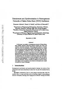
Consider a presentation consisting of a single media stream. To x notation we call the smallest displayable media unit of a given type a sample of that type (such as a video frame or an audio sample). The rate of normal play out (without considering fast play, fast forward, reverse etc.) of a single presentation is xed, but may su�er acceptable (to human perception) variations. Let Rt � rt be the normal rate and its variation, in samples per unit time, for media of type t 2 T . For example : for NTSC quality video the average rate is 30 frames per second with a variation of �5. For high delity audio the sampling frequency is 44.1 Khz, i.e. 44 samples per milli second. In most multimedia presentations a number of streams need to be synchronized. Since it is impossible to achieve perfect synchronization, in an actual system it may be necessary to take corrective action at regular intervals. Though smaller intervals provide better synchronization, the length of such an interval cannot be made arbitrarily small due to limitations on the time it takes to correct. For example, the context switch time between two threads is approximately 0.1 milli seconds[2]. Therefore it is impossible to take corrective action at ner intervals. Notice that there are about 8.8 sound samples in the duration of a context switch. Therefore, for synchronization it is not necessary to break up the sound stream to units smaller than 9 samples. 5
synchronization granules
granules of A A granules of B B
C granules of C
Figure 1: Physical and Synchronization Granules. As the example above shows, the basic manageable units of media can consist of more than one sample. We call such a unit a media granule (see Figure 1). Units of play out rates are (usually) samples per second , say R � r. Now, consider a stream that has k samples per granule. Then the play out rate is also Rk�r granules per second. By denoting � = R=k and � = r=R the same play out rate can be expressed as �(1 � �). We call � the ideal rate and � its fractional variation. Let there be n di�erent types of media streams t1 ; : : :; tn ; with rates �t1 (1��t?1 ); : : :; �t (1��t ); to be presented in parallel. Now, to take corrective action with respect to the entire collection we have to break up granules into smaller pieces. Notice for reasons stated earlier we do not want to deal with fractions of granules. For example suppose we have three types of media, A, B and C. Suppose A, B and C have rates of 6, 4 and 8 granules per second. In order to synchronize between A, B and C, we construct a synchronization granule to have a rate of 24 (Least Common Multiple of 6, 4 and 8) granules per second. Notice that the least common multiple is the smallest unit of time at which any granule can be scheduled. i.e. the scheduler need not be invoked at smaller intervals. Also the greatest common divisor (GCD) is the smallest interval at which granules of all three streams can be scheduled. Notice that the former is the least time stamp unit and the later is the least generic schedular interval. To abstract out: to accomodate granules with di�rent rates, we de ne synchronization granules. Let there be media types t1 ; : : :; tn , with rates �t (1 � �t ) for i � n. Then the rate of synchronization granules is �(1 � �) where � = LCMf�t : i � ng and � = max f �1; : : :; �n g. n
i
n
i
i
3.2.2 Parameters of an Interval An interval of a single media, with its relevant parameters, forms an atomic interval of presentation. (see Figure ( 2)) (We use the notation < id; (a; b); t; �; mf; dev ? set; ch > to denote such an atomic interval. The parameters are as follows. id : The id number of the interval. (a,b) : Begin and end points of the interval. � : Tolerence is the permissible variation in time of the boundaries of each granule from its ideal. The begining point of an interval may have some drift due to many factors such as disk seek time, network delay, etc. The end point has a delay which is the sum of the delay of the begining point and the variability in the length of the interval. 6
t : Type of media (audio, video etc.) mf : mf = master if this interval is a master, and mf = slave if the interval is a slave. The
signi cance of this concept is explained in section ( 3.5 ). dev-set : dev-set gives the set of all possible deviations between granules that should appear simultaneous in an ideal situation. This eld is a set of ordered pairs (id, deviation), consisting of one such entry per every stream that is shown parallel to the current stream. To model gaps in media streams (null media) we allow empty intervals of each media type to be considered as intervals with length (b-a) and in nite tolerance, that can be assigned to any channel capable of rendering media of the appropriate type. id : 123 type : Audio ms : { first child } dev_set : ... Media Interval 0
a
b
granule 1 0
a
granule 2 a+g
time
granule 3 a + 2g
a + 3g
time
Figure 2: An Atomic Interval of Presentation.
3.3 Combining Intervals
Multimedia compositions are produced by combining intervals in a hierarchical manner using parallel and sequential constructs. The end result is a tree structured speci cation in which the root node corresponds to the topmost level of the composition. Leaves are atomic intervals of media. Non leaves are di�erent types of constructs that are used to produce larger compositions using existing components. At present these constructs are sequential (SEQ) and parallel (PAR) compositions. As with all constructs, SEQ and PAR have parameters and must obey certain rules. Next two sections describe these in detail. Thereafter we describe properties of trees that are produced by applying SEQ and PAR recursively on atomic intervals of media. We call such trees Synchronization Relation Trees (SRT[7]).
3.4 Sequential Composition
The end result of executing a sequential construct is that media components are shown one after the other. Therefore the parameters of a sequential play out should be the order in which they play out. We have noticed that for playing out pre-speci ed intervals composed sequentially, there is no overhead between the end of one and the begining of the other. However when requests for sequential play out are made on the y, for example as in node traversal systems such as hypermedia, there can be a signi cant overhead in switching from one media interval to another.
7
3.5 Parallel Composition
The parallel construct is more complex because in addition to specifying components the following additional concerns must be addressed.
� Components must have the same ideal lengths of display. � Degree of permissible asynchrony between any two streams has to be speci ed. This would
determine the frequency (and therefore tightness) of intermedia synchronization. � One of the streams may need to be more tightly synchronized to the time line (perhaps the viewer is more sensitive to its variations than the others), and can be used as the basis for synchronizing other parallel streams, such as the sound stream in an audio-video presentation. This gives rise to a master-slave relationship among atomic descendents of a PAR node. To indicate the childrean that provide masters, every PAR node has a masters list attched to it. This list consists of one or more children of the PAR node. If it is empty, then the system clock is a master. We explain these issues below.
3.5.1 Equal Lengths Consider streams that are connected by a PAR node. All component nodes consist of granules played in sequence. The meaning of the PAR connective is that all its components begin and end at the same time. That implies that there are equal number of synchronization granules in all components, and thus there is an implied one to one correspondence between granules in distinct streams that should be played out in the same time period. From a practical point of view lengths of presentations must be integral multiples of display lengths of granules.
3.5.2 Degree of Asynchrony Due to the inherent non determinacy of resource scheduling, perfect synchrony is impossible to achieve. Fortunately, the grossness of human perception allows us to relax the one to one correspondence between granules. The degree of asynchrony between the components determines the maximum permissible time lag between any two components that are displayed simultaneously in an ideal situation. We synonymously use tolerance for the degree of asynchrony. Consider the PAR node A in Figure 3(a) with components A1 ; : : :; An ; which are themselves PAR constructs with subcopmonents Ai;1 ; : : :Ai;n ; for each i. Because the degree of asynchrony of A is the maximum permissible deviation between any two corresponding descendant granules, the degree of asynchrony of A must be at least as large as the sum of the degrees of asynchronies of A1; : : :; An. In symbols, if �i is the degree of asynchrony of node Ai then the degree of asynchrony P n of A is at least i=1 �i . i
3.5.3 Masters
Consider the example in Figure 4, where based upon �i 's, we can compute the maximum possible variations between di�erent granules of parallel streams. Since tolerance speci cations are relative, exactly one of these must be xed in time for the display times of others to be determined. We call this the master stream. Master ranges over an interval and thus disjoint intervals of time over the course of a presentation can have di�erent masters. However, for a given interval there can be only one master. 8
A1
A 11
PAR
A 12
A
PAR
A2
PAR
A 22
A 21
A3
A 31
A 22
PAR
A 21 A 12 A 11 time
A 32
(a) An SRT with two levels of PAR nodes.
(b) Maximum possible deviations of intervals.
Figure 3: A Two level SRT At each PAR node masters can be denoted by assigning a list of children. The intended meaning is that these chosen children provide masters for the composition. In case this list is empty the system clock is taken as the master. As discussed above, all slave (non master) streams are synchronized against the master. If the master itself is a media stream, then rate variation in it will propagate to the slave streams1. For example, a demonstration running for a long time may su�er a considerable stretching/ shrinking of its total running time. Some measure needs to be taken to x this defect. One possibility is to skip or pause a master stream resulting in corresponding skips or pauses of all the dependent slave streams. Discussion of policies and mechanisms for such meta-level control are beyond the scope of this paper. A PAR
A1 SEQ
masters = { A1, A2 }
A3 SEQ
A2 SEQ
M X P
P
Q mf =1
X
Y
M
N Y Q
N
time key : master stream =
mf =1 (B) Masters of SRT in (A).
(A) A SRT with masters lists and "mf" fields.
Figure 4: Masters
3.6 Synchronization Relation Tree
A set of atomic or complex presentation objects can be combined using sequential and parallel composition operators. The result is a collection of atomic intervals combined together in a tree like hierarchical structure, which we call the Synchronization Relation Tree (SRT). As the name suggest, it is a tree in which :
� Leaves are atomic intervals of presentations. � Non leaf nodes are of one of the following kinds. 1
The system clock is the only master whose rate cannot vary
9
1. (SEQ) : To denote sequential composition 2. (PAR, �, master list) : To denote parallel composition. (a) Master set indicates which component streams of the parallel construct provides masters. (b) � is the degree of asynchrony of the parallel construct. It is a real number, and as described in subsection 3.5.2, measures the maximum permissible time di�erence between granules that have to be shown simultaneously in an ideal delayless demonstration.
3.6.1 An example SRT To illustrate these concepts, consider the following example: Intended temporal relationships in a multimedia slide presentation are shown in Figure 5 (a). Note that di�erent regions associated with the various media types include video, images, and text. The presentation consists of a sequence of synchronized text, audio and visual elements of varying duration. There are nine multimedia objects in this presentation, in which six are image objects, two are audio objects and one is a text object. Image objects I11 and I21 appear d time units after audio objects A1 and A2 begin. Text object T, and image objects I12 and I22 begin at the same time, as do images I13 and I23. A SRT representation of this composition is shown in Figure 5(b). The root object, a PAR node, indicates that all its child objects must begin simultaneously. Its leftmost child, which is a SEQ node shows that a null object D precedes both I11 and I21. The null object D has a runtime of d time units. Subsequently, there is simultaneous appearance of T, I12 and I22. I13 and I23 appear together (they are children of the same PAR node) right after I12 and I22 disappear, and while T is still on. In this example tolerances are speci ed in terms of granular lengths. We assume that each Iij for i � 2 and j � 3 is of length ve granules. T is 10 granuler lengths and A1 and A2 are 20 granule lengths. So far we have not speci ed that I11, I12 and I13 are to appear in the same channel and that I21, I22, I23 are to appear in a di�erent channel. This is done at the channel assignment stage. Audio stream A1 has been chosen as the master stream for the entire presentation. PAR nodes n1; : : :; n5 have non zero tolerances speci ed as �1 ; : : :; �5:
4 Verifying Speci cations
4.1 Consistency of a Synchronization Relation Tree
In order to be demonstrable, a multimedia presentation speci ed as a SRT must be consistent. That means in theory it must not be asking for the impossible; such as, to show two segments with di�erent play out times in the same time interval. It turns out that the consistency of a SRT can be stated in terms of a few basic properties that each of its nodes must satisfy. These are tolerance consistency, interval consistency, and master consistency.
4.1.1 Tolerance Consistency Tolerance consistency refers to the conditions that must be satis ed by tolerences speci ed on a SRT. The tolerance consistency states that the tolerances of parent nodes on a SRT must be at least as large as those speci ed at their children. Notice that SEQ nodes of a SRT do not have any tolerances speci ed, but their EQ children do. 10
PAR
ε5 = 3
Presentation intended by the composer
SEQ
n5
A1 master
A2
T
Text
PAR D
ε4=1
d I 11
I 12
I 21
I 22
PAR n4
ε3=2
n3
I 13
Video
SEQ d
I 11
I 21
T
I 23 PAR
ε2 =1
n2
PAR
ε1 = 1 n1
A1 Audio
I12
A2
I 22
I 13
I23
flow of time
(a) Streams of media
(b) SRT with tolerences
Figure 5: SRT for an intended composition.
A SEQ
A1 PAR
A11
A2 PAR
A12
A21
A22
Ai PAR
Ai1
An PAR
Ai2
An1
An2
Figure 6: Parallel Composition of Sequential Streams.
11
Suppose the SEQ node A of a SRT has component PAR nodes A1 ; : : :; An with tolerances �1; : : :; �n respectively. Thus far for the play out interval of Ai , the maximum permissible time variation between corresponding granules of descendents of Ai is �i . Since the tolerance of each node is a measure of the maximum permissible time di�erence between any pair of descendant parallel streams, we must take at least maxf�i : i � n g as the tolerance of the PAR node A. This condition is called tolerance consistency of a PAR node. The discussion above implies that tolerance can be speci ed for each node in a SRT. While there are no constraints on the tolerance speci cation of leaf nodes, that of internal (composition) nodes must satisfy some lower bound constraints, since a composition node can provide a synchronization no tighter than any of its children. Let t-value be the tightest tolerance a node can provide. These are de ned as follows. � t value of a atomic node is its tolerance. � t value of a PAR node is the sum of t-values of its children. � t value of a SEQ node is the maximum of t-values of its children. Tolerance consistency can be stated as: A SRT is tolerance consistent i� the tolerance of every node in it is at least as much as its t-value.
4.1.2 Interval Consistency Interval consistency applies only to a PAR node and states that ideal lengths of presentations of its components must be equal. A PAR node with two components A and B is given in Figure 7. They have equal ideal lengths of display, and A and B have 4 and 3 synchronization granules per physical granule respectively. b-drift
A
PAR e-drift B
Figure 7: A length consistent PAR node.
4.2 Master Consistency
As discussed in section 3.5.3, every interval has a unique master. When a master is not explicitly speci ed, the system clock is considered as the master, to take care of underspeci cation. However, overspeci cation of masters is considered an error. To see how this may happen, consider a PAR node with two atomic children with all of them in the master list. Let the children be their own masters. The semantics of master list imply that both children are masters in the same interval of time which is impossible to achieve. To avoid such situations we must check for master consistency. A speci cation given by a SRT is master consistent if every interval has at most one master. In this section we present an algorithm to check consistency of master assignments, which also computes masters for disjoint time intervals. The presentation algorithm of a SRT needs this information for scheduling granules. The algorithm computes a set of (interval ID, time interval ) pairs for each node, called the master assignment set. If (id#, (a,b) ) is in the master assignment set of node A then the leaf node with id# is the master of the presentation of this SRT for the time duration (a,b), measured from the begining of the presentation. 12
Algorithm 1 (Master Consistency and Master Assignment Set) Recursively test for master consistency and compute masters as :
1. For the atomic interval I =< id; (a; b); type; �; mf; ch >, (a) I is master consistent. (b) de ne : if mf = master else MAS(I) =
�
then MAS(I) =
f
(id, (a,b) )
g
;
2. Let T be a SRT with root (SEQ) and subtrees T1 ; T2; : : :; Tn as children. Then (a) T is consistent. (b) de ne : MAS(T)
=
Sni=1 f MAS( Ti) : i � ng:
3. Let T be a SRT with root (PAR, �, master list) and subtrees T1; T2; : : :; Tn as children. Then If master list = f Tj : j � kg then
[
MAS(T) = kj=1 MAS( i) T is consistent iff there are no two
T
(id1; (a1; b1); (id1; (a2; b2)) 2
MAS(T) satisfying
(a) id1 6= id2. (b) (a1; b1) \ (a2; b2) 6= �. After running algorithm ( 1), atomic intervals I with ID id# is a master for the duration of interval (a,b) i� (id#; (a; b)) 2 MAS (root): If so we set mf = master for such intervals and mf = slave for the others.
4.3 Summarizing Consistency
For the purpose of providing an unambiguous de nition and summarizing our discussion about consistency, we provide de nition 1. It has the e�ect of consolidating various notions discussed that collectively make up our notion of consistency of a SRT. A consistent SRT is one in which all internal nodes satisfy master and tolerance consistencies and all PAR nodes satisfy length consistency. Due to the recursive nature of tree de nitions, we give simultaneous inductive de nitions of length, tolerance, master assignment set (MAS) and consistency of a SRT. The length is the ideal length of the complete multimedia demonstration. The nal tolerance computed is the least upper bound on the maximum permissible startup time disparity between granules that should be shown simultaneously in an ideal situation.
De nition 1 (Consistency and length of a SRT) We recursively de ne the concept of a consistent SRT and its length (i.e. kSRT k) as follows: � The interval I =< id; (a; b); type; �; mf; dev ? set; ch > is a consistent SRT provided that b-a is an integral multiple of display time of synchronization granules. We de ne : 1. kI k = b ? a. 2. t value of I is �. 3. MAS(I) = f ( id, (a,b)) g i� mf = master else MAS(I) = �.
13
� Let T be a SRT with root (SEQ) and subtrees T1; T2 : : :; Tn. Each Ti has length kTik tolerance �i and t value �i. Then T is consistent i� each Ti is consistent for i � n. If T is consistent, de ne 1. 2. 3.
�T = maxf �i : i � n g. kT k as Pni=1 kTik. S MAS(T) = ni=1 fMAS (Ti) : i � ng.
� Let T be a SRT with root (PAR, �, master list) and subtrees T1; T2; : : :; Tn .Each Ti has length kTik , tolerance �i and t values �i. de ne �T as Pni=1 �i. Now, T is consistent i�
1. All Children of T , i.e. T1 ; T2; : : :; Tn are consistent. If so di ne �T as; �T = max f�T ; � g. 2. Length Consistency Holds at T . i.e. kTi k = kTj k for 1 � i; j � n. Then de ne kT k = kTik for any i � n. P 3. Tolerance Consistency holds at T . i.e. � � ni=1 �i. 4. Master Consistency Holds: i.e. Let MAS(T) = [ni=1 MAS(Ti) T is consistent i� there are no two (id1; (a1; b1); (id1; (a2; b2)) 2 MAS(T) satisfying (a) id1 6= id2. (b) (a1; b1) \ (a2; b2) 6= �.
Actual rendition of a consistent SRT depends upon the system of presentation being capable to meet all speci ed tolerances. Therefore, application models need to be compared with system capabilities to check if the potential presentation platform is capable of providing data service requirements by speci ed deadlines.
4.4 Computing Tolerances
In an ideal multimedia demonstration an instant of display consists of rendering a set of granules on di�erent display devices, one per each display channel. This imposes a one to one correspondence between synchronization granules of media from all di�erent streams. We call a set of such granules a slice vector. Note that the components of slice vector come from di�erent media channels. Now a demonstration of a multimedia presentation consists of updating the slice vector at a speci ed rate. If the multimedia demonstration is speci ed by a SRT then for all moments of display the slice vector has to be determined and updated. Because of non zero degrees of tolerances speci ed at PAR nodes the correspondence between granules consituting a slice vector may no longer be one to one. Thus, several granules of a stream may qualify to occupy the same component in the slice vector at a given moment of time. Non zero tolerances also allow granules of a slice vector to drift by bounded amounts. In order to compute such drifts, for each atomic interval we compute its deviation set. The deviation set of an atomic interval is de ned to be the permissible deviation between granules of the stream and those of other parallel streams forming a slice vector. It turns out that the deviation set of an interval can be computed from the collection of tolerances speci ed on the path from the node it occupies on the SRT to the root, along with the corresponding node labels. It can be shown that this much of information is enough to determine the permissible 14
variations between granules of a slice vector. This information is also necessary to generate time stamps. The e�ect of calculating deviation sets of leaf nodes and discarding tolerances of PAR nodes can be achieved by the following algorithm. Algorithm 2 (Computing Deviation Sets) For each leaf node N do the following : 1. For every distinct pair of atomic leaf nodes N, M on the SRT nd their nearest PAR ancestor. Suppose this PAR ancestor has t value � . Then include (� , M) in the deviation set of N and (� , N) in the deviation set of M. 2. Set tolerances of all PAR nodes to null. A SRT in which the leaf nodes retain all pertinent information such as the masterhood and tolerances in the form of their deviation sets and none in leaf nodes is said to be in master normal form. The following de nition formalises master normal forms. De nition 2 (Master Normal Form of a SRT) A SRT is said to be in master normal form (MNF) i� � It is consistent. � mf of atomic intervals have been computed. � Deviation sets of atomic intervals are non empty and tolerances at PAR nodes are set to null. By applying algorithms ( 1) and ( 2) we can transform a SRT into its its master normal form. Speci cation provided by a SRT and its master normal form are identical. Notice that a master normal form of a SRT may not be unique. A SRT in master normal form fully speci es all of its synchronizations. Non temporal speci cations are necessary to completely describe its logical display.
4.5 Example Continued
:::
In section ( 3) we presented an example demonstration with the corresponding SRT in gure ( 5). Now we show a master normal form of the same speci cation. Masters are computed by applying algorithm ( 1). Notice that the original SRT in Figure ( 5) is consistent with length 20 times that of synchronization granule length. The di�erence between the SRT in Figure ( 5) and the SRT in ( 8) is that all the leaves of the latter have more attributes computed as shown in table ( 8 - B).
5 Non Temporal Speci cations Non temporal speci cations are primarily concerned with look and appearance of presentations. They can be divided into two stages. The rst stage is the assignment of streams to logical channels. This assignment is independent of the physical devices avilable at the play out site. The second stage is the mapping of logical channels to physical devices. This mapping depends upon the hardware available at the display site. For example a multimedia presentation can have three logical video channels. If the display site has only one monitor the three channels can be bound to three windows on this single monitor. Some control functions such as fast forward and rewind belong to logical channels because they translate to multimedia service parameters. Others such as brightness, contrast, volume control etc. should be provided by the physical playout device. 15
PAR
A1 master d-A1
SEQ
d
PAR
I 11 d-I11
Node
n5
n4
I 21 d-A21
PAR
Deviation
Set
I11
slave
I12 T
slave
d-I12 = {(n4, 1), (n5, 3)}
A2
slave
d-T = { (n3, 2), (n5, 3) }
d-A2
A1
master
d-A1 = { (n5, 3) }
A2
slave
d-A2 = { (n5, 3) }
I12
slave
d-I12 = { (n2, 1), (n3, 2), (n5, 3) }
I22
slave
d-I22 = { (n2, 1), (n3, 2), (n5, 3) }
I13
slave
d-I13 = { (n1, 1), (n3, 2), (n5, 3) }
I23
slave
d-I23 = { (n1, 1), (n3, 2), (n5, 3) }
n3
T d-T
SEQ
PAR
I 12 d-I12
Master
n2
I 22 d-I22
PAR
I 13 d-I13
d-I11= {(n4, 1), (n5, 3)}
n1
I 23 d-I23
(A) SRT in master normal form.
(B) Deviation sets and masters.
Figure 8: Master normal form of the example SRT.
5.1 Mechanism of Channel Assignment
The SRT of a presentation de nes temporal relationships that exist between di�erent media intervals, but it does not speci cally map streams to logical channels. Our logical channels are abstractions of windows and not of screens. To uniquely specify a multimedia demonstration, the mapping f Stream : 7! Channel g must be speci ed [3]. Our approach to channel assignment is a two step process. In the rst step, we rewrite the master normal form of a SRT in Media Type Normal Form. An SRT in media media type normal form (MTNF) is one in which : � The SRT is in master normal form. � The root node is a PAR. � It has as many children as there are di�erent types of media. � Each such child is a SRT of which all atomic children at leaves are of the same media type. Every SRT in master normal form has a media type normal form. Transformation rules to convert a SRT to its MTNF are given in appendix B. The intuitive description of the media type normal form is that the SRT speci es a time line for each media type. Intuitively the conversion to MTNF can be achieved by drawing a time line for each type and allocating each interval to the appropriate coordinates of the time line of its type. Figure 9 shows the general structure of a SRT in MTNF The second stage of channel assignment further allocates as many logical channels as necessary to each media type so that each channel presents a stream. Notice that each channel is of one speci c media type, although there can be more than one channel dedicated to a perticular media type. Channels are assigned physical devices eg. windows and speakers, that display the streams bound to the corresponding channel. The fact that several windows can appear in a screen, and 16
PAR
S1 : audio
all
S2 : video
all
S3 : text
S4 : gaphics
all
all
audio
video
text
graphics
objects
objects
objects
objects
Figure 9: The shape of a SRT in Media Type Normal Form. other similar properties of presentation management are of no relevance to properties of logical channels. The physical objects that channels abstract have the properties that:
� They are only capable of displaying media of a single type. � The device can only display a single interval of the appropriate type at a given time. To realistically model the physical devices they abstract, channels must also have these properties. Channel assignments with the following properties are called consistent channel assignments.
� All streams bound to a channel must be of the same media type as the channel. � Two intervals assigned to the same channel may have at most one time point in common, namely the end point of one and the begining point of the other.
Given a SRT in media type normal form with a consistent channel assignment for it, one can view the SRT as a set of time lines, each of which consists of a linear sequence of intervals, i.e. streams of nite duration of the same media type as the channel. All atomic streams that appear in the original SRT must appear on some channel, of the appropriate type. A SRT, which has the follwing properties is said to be in channel normal form (CNF).
� � � �
It is in master normal form. Its root is a PAR node. All children of the root are SEQ nodes. All grandchildren of the root are atomic intervals of which all siblings have the same media type.
In degenerate cases either all or some children of the root can be atomic intervals or the root itself can be an atomic interval. Figure 10 shows our example SRT in CNF. The syntactic transformation that takes a SRT in type normal form and a consistent channel assignment to it and produces its channel normal form is given in appendix B. A SRT in channel normal form is said to be a complete SRT; i.e. complete in the sense that assuming resources exists, such a SRT has all necessary parameters for proper rendition. 17
PAR
d
SEQ
PAR
(text)
(audio)
d
d
SEQ (video)
T
PAR
I 11
A1
PAR
I 21
I 12
A2
PAR
I 22
I 13
I 23
Figure 10: Example SRT in media type normal form. Channel Objects ch 1 (audio) A1, ch 2 (video) I11, I12, I13 ch 3 (audio) V ch 4 (text) T ch 5 (video) I21, I22, I23 Table 2: A channel assignment for the example SRT.
5.2 Example Continued
:::
We have seen the SRT of Figure 5 transformed into master normal form in Figure 8. Note that the type normal form of a SRT is not unique. Channel assignment makes it unique. We show one possible media type normal form of our example SRT in Figure 10. A possible channel assignment for this SRT is given in Table 2.
6 Preprocessing Speci cations Once a multimedia presentation is completely speci ed, it has to be preprocessed for demonstration. Preprocessing of a consistent speci cation entails translating speci cations to a list of service requirements with deadlines and permissible variations thereof.
6.1 Producing Service Requirements
Given the variety of architectures we have considered, following service requirements need to be calculated in order to service data requirements. 1. Generate time-stamps for logical units of data to be requested. In our time stamp generation approach all synchronizable events of media service will have common time stamps. 18
PAR
ch 1 (audio) A1
SEQ ch 2 (video)
I 11
I 12
ch 3 (audio) A2
I 13
SEQ ch 4 (text)
2d
SEQ ch 5 (video)
T
I 21
I 22
I 23
Figure 11: The channel normal form of the example SRT. 2. For each media type generate streams of data that should be delivered within successive time units. We now describe these steps in detail.
6.2 Time-stamp Generation
For a single media stream, the Relative Time Stamp (RTS) of a synchronization granule is the number of such granules that come before it. For a multimedia presentation consisting of a number of di�erent media channels, each channel contributes one media granule per time slice. The ow of a set of media streams in each such time unit can be visualized as the progression of a wavefront. The vector consisting of granules from the set of channels at a point in time is called the slice vector at that time point, with the value of the time point being the time stamp of the slice vector. In case of a ideal delayless platform, every granule in a slice vector has the same time stamp. When non zero asynchrony is speci ed for PAR nodes, a particular media granule may belong to di�erent slice vectors with di�erent time stamps. Time stamp generation in a similar context is discussed by Rangan [9] et.al. However they consider a set of media streams across which there is a single parameter of asynchrony that speci es the maximum tolerance between any pair of streams. Due to the tree structured hierarchical speci cation of SRT, we must satisfy a number of asynchronies across di�erent streams. To handle this, we provide a set of vectors of granules, each of which is a valid wavefront for a time slice of media display. Furthermore, to facilitate data services, an interval of possible display is constructed for each granule, called the show time of a granule. This is the only time interval in which this granule can be shown. Let S be a given SRT with an ideal display time of t granules. We present the time stamp generation algorithm in two stages. In the rst stage we calculate the time stamps of each media granule, assuming that all asynchronies are zero. This is called an ideal time stamp (I stamp). In the second stage we compute the permissible deviations due to speci ed asynchronies. In this stage we also compute valid wavefronts for each time slice of display. If the speci ed asynchronies are su�ciently small, then there may be only one valid wavefront for a given time slice. Ideal time stamps can be assigned by associating a clock with the same synchronization granularity as media streams and reading o� the value the clock assigns to each media granule. This is achieved by combining the given SRT with a special media stream of media type CLOCK and length k S k. The show time of a granule depends upon the master of the stream it is coming from. If the stream interval is a master then the interval of display of the granule is restricted to its ideal time slice. If the stream is a slave then the interval of display is centered around the ideal time slice with a maximum displacement equal to the tolerance it is allowed to have with its master stream. 19
This can be calculated from the deviation set of the stream containing the granule. Slice vectors are calculated so that constraints enforced by deviation sets on all active streams are satis ed by the contributing granules. We present details in Algorithm 3. Algorithm 3 (Time Stamp Generation) Let M be a master stream and Si, for 1 � i � n, be slave streams. For a Given a SRT named S, 1. Compute Ideal Time stamps : (a) Create Clock : Create an interval of type clock and length k S k, Called CLOCK(S). (b) Connect CLOCK(S) with S using PAR: Let U be PAR(CLOCK(S), S). (c) Assign Time stamps to U: Each media granule in CLOCK(S) has a time stamp which is the number of granules of CLOCK(S) before it. Granules in the demonstration acquire the time stamp of the granule of CLOCK(S) with which they are concurrent. This is their ideal stamp (I-stamp). 2. Compute Show Times : For each granule we calculate its possible interval of display as follows. � If the granule is from M then its show time is its I-stamp. � If the granule is from any Si, then let �max = max f tolerance | (node, tolerance) 2 Deviation-Set(M) \ Deviation-Set(Si) g. Now take [I ? stamp ? b�max c; I ? stamp + b�max c] as the possible interval of display (show time) for the given granule. 3. Compute all Wave Fronts for Time Slices \t" : Let ui for 0 � i � n, be the distinct streams that contribute granules to the slice vector at time slice t. Let index i = m correspond to the master stream and i = 0 correspond to the stream CLOCK(S). The valid wavefronts are vectors < u0; : : :; un > that satisfy: � um and u0 are the granules with I-stamp \t". � All other granules ui; uj from slave streams si; sj should be chosen to satisfy the condition that for all nodes N on the SRT if (N, �) 2 Deviation Set(I) \ Deviation Set(J) then k(I-stamp of ui) - (I-stamp of uj ) k � �. As a consequence of Algorithm 3 for every time slice one of several granules of a media stream may be selected. Conversely, each media granule can qualify to be shown in more than one time slice. All of these options are valid within the limits of asynchrony accepted. In actual play out exactly one of these wavefronts is presented. Achieving synchronization for a prespeci ed SRT has to depend on the platform that runs the display.
6.3 Example Continued
:::
Continuing our running example, we apply algorithm 3 to our SRT to produce show times for granules and valid wavefronts for some example time slice. The fourteenth time slice has been chosen to demonstrate our calculations. Figure 12 shows the composed presentation with calculated deviation sets for atomic intervals. Next two subsections illustrate the calculated show times for the granules with ideal time stamp 14, some possible wavefronts and one impossible wavefront. 20
Node
T (text) I1 (video) I2 (video) A1 (audio) A2 (audio) CLK(S)
Master
Deviation
Set
d-I11= {(n4, 1), (n5, 3)}
I11
slave
I12 T
slave
d-I12 = {(n4, 1), (n5, 3)}
slave
d-T = { (n3, 2), (n5, 3) }
A1
master
d-A1 = { (n5, 3) }
A2
slave
d-A2 = { (n5, 3) }
I21
slave
d-I12 = { (n2, 1), (n3, 2), (n5, 3) }
I22
slave
d-I22 = { (n2, 1), (n3, 2), (n5, 3) }
I13
slave
d-I13 = { (n1, 1), (n3, 2), (n5, 3) }
I23
slave
d-I23 = { (n1, 1), (n3, 2), (n5, 3) }
CLK(S)
{ }
fourteenth time slice (A) Presentation of the SRT
(B) Deviation sets and masters.
Figure 12: Presentation and Deviations of the example SRT Channel Show Time CLOCK(S) 14 A1 (master) 14 A2 [11, 17] I1 [11, 17] I2 [11, 17] T [11, 17] Table 3: Show Times for the fourteenth granules from di�erent streams of the example SRT
6.3.1 Show Times
Table ( 3) gives possible show times for granules with ideal time slice 14 in the di�erent channels. These have been calculated using Algorithm ( 3). Notice that granules from master streams and the clock will always have one time stamp for their show times. Granules from slave streams can have show times stretching over a longer interval around their ideal time stamps.
6.3.2 Possible Wavefronts for time slice \14" of the example SRT Table 4 gives some possible slice vectors for the fourteenth time slice of our example presentation. These have been calculated by using algorithm 3. We now explain how some of these vectors are obtained. Consider the second and the third rows of Table 4. Notice that the clock and the master stream (A1) always demonstrate granules with I-stamp 14. Consider stream A2. According to Table 3 it can show any of its granules with I-stamps 11 through 17. These are calculated in step (2) of Algorithm 3. Notice that the deviation set for the intervals A1 and A2 (notation: d-A1 and d-A2) is f (n5, 3) g, and therefore d-A1 \ d-A2 is f (n5, 3) g. Suppose we picked the granule with I-stamp 12 as the candidate from stream A2. Suppose we want to choose granules from streams I1 and I2. The deviation sets for I12 and I22 (notation d-I12 and d-I22) calculate to f (n2, 1), (n3, 2), (n5, 3) g. Hence their intersection is f (n2, 1), (n3, 2), (n5, 3) g. Part (3) of algorithm 3 implies that the contributing granules of I1 and I2 may have a maximum ideal time stamp di�erence of 1, because (n2, 1) 2 d-I12 \ d-I22. As 21
14 CLOCK(S) 14 A1 14 A2 11 I1 11 I2 11 T 11
14 14 14 11 12 13 12
14 14 14 11 12 13 12
Table 4: Slice vectors for the fourteenth time slice of the example SRT it appears in line 3 of Table 4, let us choose 12 and 13 as the contributing granules from streams I1 and I2. When choosing granules from T we must choose them so that all conditions given by the intersections of appropriate deviation sets are satis ed.
6.4 Wavefront: Progression of the Slice vector
Up to now, we have computed the set of all possible slice vectors of a time slice and show times for each media granule. In a multimedia presentation successive slice vectors are shown one after the other. The propagation of slice vectors can be thought of as an advancing wavefront. At any time slice during the presentation, given the present position of the wavefront, the task is to compute the next position that the wavefront will advance to in the next time slice. Notice that Algorithm 3 does not calculate this new position. It only provides a procedure to compute all possible slice vectors, any of which is a valid candidate for the new wavefront. A number of policies can be used to select the next slice vector to advance the wavefront, each with its associated tradeo�s. Following are a few of them.
Closest to the Ideal At each time slice, select the wavefront that has the least standard deviation
from the wavefront given by the ideal time stamp. We call the corresponding algorithm the Idealistic Wavefront Algoritm. Least Discontinuous At each time slice select the wavefront that shows the most number of granules in sequence. We call the corresponding algorithm the Continuous Wavefront Algorithm. All polices may entail some skipping and pausing of media streams. There are two issues that have to be considered in evaluating di�erent algorithms for their relative merit, namely the time e�ciency of the computation and the quality of service of the output.
6.5 Data to be Delivered and Retained in Each Time Slice
In general, a media granule of any type consists of some constant number of synchronization granules. Also, time stamps are assigned to synchronization granules. However, since media are delivered in media granules, the time stamps need to be translated from synchronization granules to media granules. To make such a translation, time stamps assigned to all synchronization granules of a given media granule are assigned to the corresponding media granule. Also, as a consequence of our time stamp assignment algorithm, a synchronization granule may contain more than one time stamp. As a consequence, eventually a media granule may end up being assigned a set of time stamps. A media granule can be demonstrated at a time slices ccorresponding to any time stamp associated with it. Consequently, the earliest time that a media granule may have to be present at 22
the display site is the earliest time stamp assigned to it, and the latest time it may have to remain there is until the elapse of the last time stamp. Hence, each display site must have enough memory to retain all such media granules for the interval of time between the earliest and the latest time stamps associated with the current slice vector. As discussed above, for each time slice we can compute all the media granules that should be in memory at each display site. The total memory required to retain all such media granules is the most memory requirement per display site at each time interval. The upper bound of such memory requirements at any given display site over the lifetime of the presentation determines the local memory required for the demonstration.
6.6 Wavefront Progression Algorithms
The computation of the next wavefront depends upon the current wavefront, and the available data granules at the display site. Although we have computed possible wavefronts for each time slice, the ability to demonstrate any acceptable wavefront depends very much on the data available at the local display site. If some media granules that are expected at the display site have not arrived at the required time, then our algorithms will not display an acceptable wavefront. To make the presentation of wavefront progression algorithms uniform, the following de nitions are introduced.
De nition 3 (Next Granule) For any media stream, let F be the set of media granules that are
present at the display site, p is the ideal time stamp and q is the time stamp of the current granule under display. Let [a,b] be the time slice of the granule. Then p 2 [a,b]. Ideal(F, [a,b], p, q) and Cont(F, [a,b], p, q) compute the time stamp of the next granule of this media to be shown in time slice \t" under the Idealistic and Continuous wavefront algorithms. They are de ned as follows: 1. If p 2 F then de ne Ideal(F, [a,b], p, q) = Cont(F, [a,b], p, q) = p. 2. If p 62 F then let Ideal(F, [a,b], p, q) be de ned as f 2 F satisfying:
� kf ? pk = min f kx ? pk : x 2 F g. � f � q. If there are two values for f satisfying conditions above, say f1 and f2 , and only one of them (say) fi satis es fi 2 [a; b], then choose fi as Ideal(F, [a,b], p, q). If both f1 ; f2 2 [a; b] then choose an arbitrary f1 as Ideal(F, [a,b], p, q). 3. If p 62 F then de ne Cont(F, [a,b], p, q) as f 2 F satisfying:
� kf ? (q + 1)k = min f kx ? (q + 1)k : x 2 F g. � f � q. If there are two say f1 and f2 , satisfying conditions above and only one of them (say) fi satis es fi 2 [a; b], then choose fi as Cont(F, [a,b], p, q).If both f1 ; f2 2 [a; b] then choose an arbitrary f1 as Cont(F, [a,b], p, q). For each of the demonstration policies (i.e. idealistic and continuous) at each time p, compute the appropriate value of Ideal(F, [a, b], p, q) or Cont(F, [a, b], p, q) and demonstrate the media granule with the corresponding time stamp. 23
7 Concluding Remarks This paper presents a new formulation of synchrony that is su�cient to satisfy the requirements imposed by multimedia synchronization. This synchronization mechanism extends readily available methods by relaxing the strictness of synchronization from a point of time to an interval of time acceptable within the limits of perception. The speci cation of looser synchronization is used by the system to � Achieve better resource allocation. � Recover from transient and non-deterministic system overloading. We have provided two constructs PAR and SEQ to be used to build complex compositions from simple components. Multimedia demonstrations built this way constructs a tree of synchronization requirements as their speci cation. These trees of synchronization requirements can be translated into a collection of parallel media streams with synchronization requirements between di�erent portions of them. This translation is achieved in several steps. By preprocessing SRT's we calculate possible vectors of media granules that can be shown in each time unit. The progression of this vector through the life time of the demonstration can be visualized as an advancing wave front that propogates in discrete steps. Given the state of the wave front and the most recently arrived media packets at the display sites there can be di�erent policies and algorithms to compute the state of the wave front in the next increment of time tick.
24
References [1] Allen, J.F., Maintaining Knowledge about Temporal Intervals. Communications of the ACM, November, 1983 [2] Bach, M.J., The Design of the Unix Operating System. Prentice Hall, 1989 [3] Hardman, L., Bulterman, D.C.A., and van Rossum, G. The Amsterdam Hypermedia Model: Extending Hypertext to Support Real Multimedia. Technical Report 9306, CWI, University Of Amsterdam [4] Hodges, M.E., Sasnett, R., and Ackerman, M.S., A Construction Set for Multimedia Application. IEEE Computer, October, 1991. [5] Little, T.D.C., and Gafoor, A., Synchronization and Storage Model for Multimedia Objects, Selected Areas in Communications, Vol 8, 1990. [6] Little, T.D.C., Ghafoor, A., Chen, C.Y.R., Chang, C.S., and Berra B.P., Multimedia Synchronization, Data Engineering Bulletin, 1991 [7] Kim, W., Kenchammana-Hosekote, D., Lim, Ee-Peng., Srivastava, J., Synchronization Relation Tree : A Model for Temporal Synchronization in Multimedia Presentations Technical Report TR92-42, Dept of Computer Science, Univ. of Minnesota [8] Rangan, V. P., and Vin, H. V., Designing File Systems for Digital Audio and Video, Proceedings of the 13th Symposium on Operating System Principles., October 1991 [9] Rangan, V. P., and Vin, H. V., Designing a Multiuser HDTV Storage Server IEEE Selected Areas of in Communications, Vol 11, No1, Jan, 1993. [10] Rangan, V. P., and et al. A Test bed for Digital Audio and video Usenix Proceedings, 1991 [11] Steinmetz, R., Synchronization Properties in Multimedia Systems. IEEE Journal on Selected Areas in Communications, Vol 8, April 1990 [12] Terry, D. and Swinehart, D.C. Managing Stored Voice in the Etherphone System. ACM Transctions on Computer Systems, Febraury, 1988 [13] Vin H.M. et.al., Multimedia Coferencing in the Etherphone Environment. IEEE Computer, October, 1991
A Expressive Completeness of SRT's In gure [1] we show how each of 11 possible temporal relationships can be directly de ned using SRT's. Meet and Before relationships can be directly represented by a SEQ node except that a delay object has to be inserted between child objects of the latter relationship. Equal relationship can be represented by a PAR node. Start, Overlap, During and Finish relationships can also be represented by a combination of PAR nodes and SEQ nodes by inserting appropriate delay objects. Except the equal relationship, all other temporal relationships have inverses which are not shown in the diagram. 25
Ma
d
Mb
Ma
Mb
Ma db
SEQ Ma
d
Mb
Ma
Ma before Mb
SEQ Ma da
db
Ma equals Mb
d
d
Ma
Mb
SEQ
Mb
d2
Ma during Mb
PAR
PAR SEQ
Mb Ma
Mb
d
SEQ d
Ma starts Mb
Ma
Ma finishes Mb
Figure 13: Temporal Relationships and their equivalent SRTs.
26
Mb
Mb
Ma overlaps Mb
PAR
d1 Ma
PAR
SEQ
Mb
Ma
Mb
Mb PAR
Ma meets Mb
d2
Ma
Ma
Mb
SEQ
Ma
d1
da
Mb
B Normal Forms
B.1 Purpose of Normal Forms
Various normal forms of SRT's were discussed in section ( 4). Speci cations of a multimedia demonstration given in the form of a SRT by the composer is eventually transformed into a set of service requirements. This transformation has several intermediate stages. In these stages the original SRT is transformed in to some normal form. Each of these intermediate normal forms are produced by applying an algorithm to a SRT that has certain special properties. This appendix describes algorithms that transform a SRT satisfying required preconditions to one in the appropriate normal form. The main purpose of having a SRT in a given normal form is the technical fact that some algorithms apply only to SRT's in speci ed normal forms. For example the algorithm that transform a SRT to media type normal form requires that the original SRT be given in master normal form. Also SRT's in a particular normal form corresponds to some intuitive way of expressing the set of speci cations represented by itself. For example a SRT in media type normal form is a parallel composition of di�erent SRT's; one for each distinct type. Notice that by de nition any SRT in any normal form is temporally consistent.
B.2 Master Normal Form
By de nition a SRT in master normal form has all synchronization and masterhood information stored in leaf nodes. Intuitively this corresponds to a SRT of which internal nodes serve the sole purpose of placing leaf nodes on the relative time line. Any consistent SRT is transformed into a SRT in master normal form by applying algorithms ( 1) and ( 2) in that order.
B.3 Media Type Normal Form
A SRT in media type normal form is one which is in master normal form and has a PAR root of which there are as many children as the number of distinct types. All atomic descendents of these children are of the same media type. Intuitively its a SRT in MTNF is a parallel composition of SRT's one for each distinct media type. The mapping that transforms a SRT in master normal form to one in type normal form is given in algorithm ( 4). It consists of processing nodes of a SRT in master normal form in a bottom up fashion. In doing so algorithm ( 4) treats PAR, SEQ and atomic nodes di�erently.
Notation: Let PAR(A1; A2; : : :; Ak ) = PAR(Nki=1 Ai ) and SEQ(A1; A2; : : :; Ak) = SEQ(Nki=1 Ai). Algorithm 4 (Mapping : Master Normal Form 7! Media Type Normal Form) De ne the mapping T : Master Normal form 7! Media Type Normal Form as follows. 1. Suppose T is a single atomic node of media type t1 . Suppose that t 62 ft2 ; : : :; tn g are all the other types. Let dt be a delay interval of type ti and length kT k for 2 � i � n. Then de ne T (T ) = PAR(T; dt2; : : :; dt ): i
n
2. Suppose T is a SRT with a SEQ root. I.e. let T = SEQ(T0; : : :; Tm). Suppose that for each j � m T (Tj ) = PAR(Bj;1 ; : : :; Bj;n ) where each Bj;i is a SRT with all leaves of media type i. Then de ne m On O T (T ) = PAR( SEQ( Bj;i )) i=1
27
j =0
3. Suppose T = PAR(T0; : : :; Tm) be a SRT with a PAR root. Suppose that for each j � m, T (Tj ) = PAR(Bj;1; : : :; Bj;n) where each Bj;i is a SRT with all leaves of media type i. Then de ne m On O T (T ) = PAR( PAR( Bj;i)) i=1
j =0
Figure 14 illustrates steps 1, 2 and 3 of algorithm ( 4) by means of an example. SEQ A :audio
PAR A1
V1
PAR A :audio
PAR PAR
T1
A2
PAR
V2
T2
A1
V1
PAR
d : video
d :text
A1
(1) Atomic Intervals
A2
V1
T1
A2
V2
T2
PAR
SEQ
SEQ
PAR
SEQ
V2
T1
(2) SEQ Construct
T2
PAR A1
PAR A2
V1
PAR V2
T1
T2
(3) PAR construct
Figure 14: Transformation T applied to three forms of nodes of SRT's.
B.4 Channel Normal Form
Channel Normal Form expresses a SRT as a parallel composition of distinct channels. These are logical channels that consists of sequences of homogeneous (of the same media type) streams. Every such channel can be displayed on a single presentation device. The present subsection provides a mapping from Media Type Normal form to Channel Normal Form of SRT's, given in algorithm ( 5). One of the issues that has to be dealt with in algorithm ( 5) is the following. Suppose we have a SRT given as a parallel composition of two sequential compositions of the same type. Suppose that in addition both sequential compositions have the property that when one of them shows a non-delay interval the other parallel stream shows a delay interval. Then both of these streams can be recombined as a single sequential stream that has all non-delay intervals that were in both the original parallel streams. We call this operation parallel merging of the two streams. We provide the following formal de nition for merging of two mergable streams. This auxhillary operation is used in algorithm 5. De nition 4 (Parallel Merging of Mergable Streams) We de ne mergable streams and merging of such streams as follows. � Suppose that T = PAR(Nki=0 SEQ(Nmj=0 Bi;j )) where all intervals Bi;j are of the same media type. Suppose N that the display time interval of Bi;j is Ii;j = [ai;j ; bi;j ]. Then we say that streams fSEQ( m j =0 Bi;j ) : i � kg are mergable i� they satisfy : If Bi;j is a non-delay interval then every Bk;l for k 6= i that satis es Ii;j \ Ik;l 6= � is a delay interval. 28
� Suppose fSEQ(Nmj=0 Bi;j ) : i � kg mergable. Then we de ne parallel merging of fSEQ(Nmj=0 Bi;j ) : i � kg as given below. 1. Suppose Ii;j = [ai;j ; bi;j ]. Let ah for 1 � h � H be a monotonically increasing ordering of ai;j . If ai;j = ah for some h then de ne Bh = Bi;j . 2. Let dh be a delay interval of the same type as Bi;j , assigned to the same channel, with length jah+1 ? ah j for 1 � h ? 1. Then de ne H O MERGE(T ) = SEQ( (SEQ(B ; d )) h=1
h h
Figure ( 15) shows two parallel mergable streams. Key
PAR
non-delay
delay
merge
Figure 15: Parallel composition of mergable streams and their parallel merging The following result about channel assignments is implicitly used in algorithm ( 5).
Theorem 1 N Suppose thatNthere is a consistent channel assignment that assigns all atomic intervals N m m k Bi;j of PAR( i=1 SEQ( j=1 Bi;j )) to the same channel. Then fSEQ( j=1 Bi;j ) : i � kg is mergable.
The third step of algorithm ( 5) is valid because theorem ( 1).
Algorithm 5 (Mapping : Media Type Normal Form 7! Channel Normal Form) De ne the mapping :
U : [ Media Type Normal form ]� [ Consistent Channel Assignment ] 7! [ Channel Normal Form ] as follows. Let fc1; : : :; ck g be the collection of logical channels assigned to streams of the current SRT.
1. Suppose T is a single atomic node assigned to channel c1. Let dc be a delay interval having the media type of channel ci and length kT k for 2 � i � k. Then de ne U (T ) = PAR(T; dc1 ; : : :; dc ) i
k
29
2. Suppose T is a SRT with a SEQ root. I.e. let T = SEQ(T1; : : :; Tm). Suppose that for each i � m, U (Ti) = PAR(Bi;1; : : :; Bi;k ) where each Bi;j is a sequential composition, assigned to channel j . Then de ne k m O O U (T ) = PAR( SEQ( B j =1
i=1
i;j ))
3. Suppose T = PAR(T1; : : :; Tm). Suppose that for each i � m, U (Ti) = PAR(Bi;1 ; : : :; Bi;k ) where each Bi;j is a sequential composition of streams, assigned to channel j . Then de ne
U (T ) = PAR(
m Ok MERGE(PAR(O B j =1
i=1
i;j )))
Theorem ( 1) and the consistency of the channel assignment guarantee that fBi;j : i � mg is meargable for each 1 � j � k.
Figure ( 16) shows key steps of algorithm ( 5). SEQ A: ch1
PAR c11
c12
PAR A: ch1
PAR PAR
c13
c21
PAR
c22
c23
c11
c12
PAR
d: ch2
d: ch3
c11
c21
channel 1
(1) Atomic Intervals
c12
c13
c21
c22
c23
PAR
SEQ
SEQ
PAR
SEQ c21
c13
channel 2
c23
channel 3
(2) SEQ Construct
merge c11
c21
channel 1
merge c12
c21
channel 2 (3) PAR construct
key : atomic stream c ij is assigned to channel i.
Figure 16: Transformation U applied to three forms of nodes of SRT's
30
merge c13
c23
channel 3