May 11, 2005 - H. Y. Guo, A. L. Hoffman, R. D. Milroy, K. E. Miller, and G. R. Votroubek. Redmond Plasma Physics Laboratory, University of Washington, ...
PRL 94, 185001 (2005)
week ending 13 MAY 2005
PHYSICAL REVIEW LETTERS
Stabilization of Interchange Modes by Rotating Magnetic Fields H. Y. Guo, A. L. Hoffman, R. D. Milroy, K. E. Miller, and G. R. Votroubek Redmond Plasma Physics Laboratory, University of Washington, Seattle, Washington 98195, USA (Received 25 June 2004; published 11 May 2005) Interchange modes have been a key limiting instability for many magnetic confinement fusion configurations. In previous studies intended to deal with these ubiquitous instabilities, complex, transport enhancing, minimum-B producing coils were added to the otherwise simple linear mirror plasma. Possible solutions for returning to a simple symmetric mirror configuration, such as ponderomotive fields, are weak and difficult to apply. A new method is demonstrated here for the first time, utilizing rotating magnetic fields that are simple to apply and highly effective. A simple and easily comprehensible theory has also been developed to explain the remarkable stabilizing properties. Although this work has been performed on field reversed configurations, it should have a wide application to other confinement schemes, and could become a cornerstone for high-� plasma stability. DOI: 10.1103/PhysRevLett.94.185001
PACS numbers: 52.55.Lf, 52.35.Py
Interchange modes are ubiquitous instabilities present in linear plasma columns such as symmetric mirrors (which appear as flutes and are often referred to as fluting) and many other low magnetic shear confinement configurations such as spheromaks and reversed field pinches. These instabilities are usually driven by pressure gradient in an unfavorably curved magnetic field, interchanging a flux tube containing high pressure plasma with another flux tube containing low pressure plasma, ultimately limiting the plasma �. Field reversed configurations (FRCs) have some similarities to mirror plasmas, except that the azimuthal diamagnetic current is so high that the external field is reversed on the inside, forming a prolate, high-beta, compact toroid [1]. In FRCs the ions generally carry much of the diamagnetic current, and the concomitant plasma rotation � produces a much more dominant instability drive force. Present FRCs are usually highly kinetic, with small ratios of minor radius a to external gyroradius �i . The dominant instability under these conditions is an axially uniform, rotating, elliptical (n � 2 azimuthal distortion) interchange mode, which has been termed the rotational n � 2 instability in FRCs due to the principal drive force being due to rotation. Although the principal driving forces are different, both pressure gradient (coupled with bad curvature) and centrifugally driven interchange instabilities are essentially Rayleigh-Taylor fluid instabilities driven by an unfavorable ‘‘gravitational’’ gradient, and have been analyzed as such in most textbooks [2]. These instabilities have been stabilized in both mirror plasmas [3] and FRCs [4] by the application of steady multipole fields. However, from technological and confinement considerations, multipole fields are highly undesirable, and the steady magnetic fields should be axisymmetric. In the gas-dynamic regime where the mirror length exceeds the ion mean free path, stabilization may be possible due to the plasma streaming out the mirror ends in the favorable curvature region [5]. In the normal kinetic regime, where lifetimes are governed by velocity space diffusion into the loss cone, strong rf fields 0031-9007=05=94(18)=185001(4)$23.00
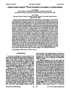
have been demonstrated to provide stability to interchange (fluting) through ponderomotive forces [6]. This is a fairly complex second order phenomenon related to how gradients in the rf electric fields respond to plasma perturbations [7]. A much more direct method is available through the use of rotating magnetic fields (RMF), which provide a strong inward force proportional to the RMF magnetic pressure. This force increases when the plasma bulges out due to increases in the field line curvature, and has been demonstrated to stabilize the FRC rotating n � 2 interchange mode in the Translation, Confinement, and Sustainment (TCS) RMF driven FRC facility without using static multipole fields. This Letter presents the results. Rotating magnetic fields have been investigated for many years as a current drive technique [8,9], culminating in a long series of rotamak experiments at Flinders University in Australia [10]. RMF has recently been adopted as both an FRC formation and current sustainment technology in TCS. A detailed description of the TCS facility can be found in Ref. [11]. An end-on sketch of the RMF lines is shown in Fig. 1 for both a vacuum and a
Antennas
Wall
rs
hg2004.sta.8
FIG. 1 (color online). Calculated RMF lines for TCS antenna geometry without and with conducting plasma column. Antenna locations are shown on the vacuum field plot, with field lines shown at the time when only the vertical field producing coils are carrying current.
185001-1
2005 The American Physical Society
week ending 13 MAY 2005
PHYSICAL REVIEW LETTERS
plasma case. The RMF is produced by oscillating axial currents in the antenna rods, whose radial locations are sketched in the figure. Phasing the currents in the vertical field producing coils 90 � from those in the horizontal field producing coils results in the rotating field. A conducting plasma produces axial shielding currents which limit the RMF penetration. In an FRC the penetration distance is self-adjusting and related to the ratio of actual azimuthal plasma current and the maximum possible azimuthal current if all electrons were rotating at the RMF frequency !. It is the driven, near synchronous rotation of the outer electrons which allows the RMF to penetrate beyond the simple skin depth � �2 k =�0 !�1=2 , where k is the plasma resistivity [12]. The actual penetration distance � can be obtained from the previous formula by substituting ! � � ! � !e for !, with !e being the electron rotation frequency. RMF current drive, with vacuum field B! , works by producing a torque on the electrons equal to TRMF � 2�rs � B2! =�0 :
(1)
rs is the FRC separatrix radius. The actual forces are produced by the hjz Br i oscillation of the electrons in phase with the radial component of the RMF [12]. The torque is distributed throughout the plasma column by radial flow and, for an FRC, the magnetic flux increases if TRMF exceeds the resistive torque T � 0:5� ? hne e2 �!e � !i �ir4s due to electron-ion friction. Equilibrium is achieved when TRMF equals T . The RMF also produces a radial inward force hjz B� i due to the interaction of the electron oscillation with the azimuthal component of the RMF. This force not only contributes to the radial force balance, supplementing the standard r�Bz 2 =2�0 �, but can also provide stabilization against interchange. In the limit of low RMF penetration ( � =rs < 0:3), Ref. [12] gives the following expressions for the RMF fields and driven axial currents in the region r < rs : s������� 2rs � � � B! e��rs �r�= ei !t����=4��rs �r�= ; (2) Br � r r r���� r � � B� � 2 s B! e��rs �r�= ei !t����=2��rs �r�= ; r
(3)
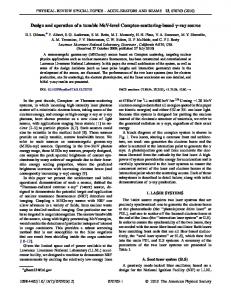
code [13], is shown in Fig. 2. The ratio of radially integrated averaged force (over an RMF cycle) to the external magnetic pressure Be 2 =2�0 is plotted for a value of �max =rs � 0:1. Calculations for various values of �max =rs up to 0.3 show that the first order change in Fr is Fr1 � �
2B2! rs �2�rs �r�= � � e ; rs �0 � r
(6)
corresponding to variations in B� of B! �2 � �=rs �. (The approximate doubling of B� over the vacuum value B! is due to image currents in the conducting plasma column, and the additional increase due to the distortion � is due to concentration of the image currents where the radius of curvature decreases.) Fr1 is inward when the plasma bulges outward, which is the fundamental stabilizing mechanism. A simple analysis of the Rayleigh-Taylor instability, such as in [2], shows a growth rate of order (‘g’= � �1=2 where ‘g’��2 r � �Fr1 � =��� and � is the scale length of the density gradient. (For pressure gradient driven interchange modes, the equivalent unstable Rayleigh-Taylor gravitational drive is 2p=�Rc with p and Rc being the pressure and the field line curvature.) If we integrate this quantity over p��� the unstable region between the field null R (R � rs = 2 for an elongated FRC) and the separatrix rs , and ignore all other effects, we arrive at a simple stability criterion, B2! =�0 > h�i�2 r3s =4 � . Taking � � �2=3� � �rs � R� for a typical FRCs density profile, this reduces to B2! =�0 > 1:3h�i�2 r2s :
(7)
Theta-pinch formed FRCs generally develop a rotating n � 2 interchange mode when they spin up too close to the ion diamagnetic velocity, � � !i � �D � 104 Ti �eV�=rs 2 �m�Be �mT� rad= sec . This instability has previously only been measured visually [14], and takes 1.0 Plasma boundary 0.8 2 r /(Be /2µ0)
PRL 94, 185001 (2005)
0.6 Wall
� z =! k � !rB � r = k : jz � !E
0.4
(4)
Averaging over an RMF cycle and using the definition of � , the radial force due to the RMF can be written as Fr � � hjZ B� i � �
2B2! � 0 �
rs �2�rs �r�= � e : r
0.2 0
90
180
270
360
(5)
A stabilizing force derives from how the radial force responds to a radial plasma distortion ��r; ��. A calculation of the azimuthal dependence of the radial force for an elliptically distorted FRC, utilizing a RMF penetration
FIG. 2R(color online). Total integrated stabilizing inward RMF force hjz B� i as a function of azimuthal angle for an elliptical distortion with �max � 0:1rs , normalized to the normal steady confinement pressure Be 2 =2�0 . An end-on sketch of the FRC and the resultant RMF lines are also shown.
185001-2
week ending 13 MAY 2005
PHYSICAL REVIEW LETTERS
PRL 94, 185001 (2005)
the form of a severe elliptical distortion leading to contact with the plasma tube walls in a few growth times. It has been stabilized by steady multipole fields of magnitude Bm 2 =2�0 � 0:5h�i�2 rs 2 [15]. Nondestruction at lower rotation rates may be due to a combination of lower growth rates and finite Larmor radius (FLR) effects since the nonsustained FRCs tended to spin up to the ion diamagnetic velocity in the same time scale that they lost half their particles and magnetic flux [16]. RMF formed and sustained FRCs also tend to be spun up to their diamagnetic velocity, but in the electron diamagnetic direction due to the torque exerted by the RMF. For TCS, this velocity peaks at about � � 7 � 104 rad= sec , which was always less than 1=10 the RMF frequency ! [17]. RMF driven FRCs in TCS tended to be about 0.75 m in diameter, 1.6 m long (the same length as the RMF antennas), and have densities of order 1019 m�3 (proportional to B! =!1=2 ). The total electron plus ion temperatures varied between 30 to 100 eV, with external magnetic fields Be of order 15 mT. The rotating n � 2 instability was usually nondestructive, with its development sensitive to closeness to the plasma tube wall at rw � 0:40 m. The n � 2 mode has the same rotation frequency as the bulk plasma, with axial mode number kz � 0. In order to examine the contribution of the RMF to stability, some discharges were run using separated RMF antennas, with various gaps in the center. Operating with a large central gap did not affect the rotational frequency �, but always resulted in the development of a rotating n � 2 instability, which could easily be
seen on any cross-tube diagnostic such as an interferometer. Two pass interferometer traces are displayed in Fig. 3 for two nearly identical discharges with the same r�$ excluded flux radii (rs � r�$ ), but with different central gaps of 0.05 and 0.35 m. Tomographic reproductions are also shown at 1.4 msec into the discharges, which also indicate the n � 2 distortion for the larger gap case. In both cases the FRCs lasted the full 2.5 msec of the applied RMF, about 25 times their normal unsustained flux decay times. The nature of the n � 2 rotating interchange mode could also be examined using an internal magnetic field probe. Bz �r� data from such a probe for a continuous antenna case, where the instability is observed visually, are shown in Fig. 4. The instability was localized in the region outside the field null, and is easily recognized by the �20 kHz oscillation beginning at about 1.0 msec as the applied RMF decreases due to running down of its capacitor bank power supply. A contour plot of the frequency spectrum of the probe signals as a function of radius is also shown. Plots are shown in Fig. 5 of the relative magnitudes of the plasma pressure (proportional to density since the temperature is approximately uniform), the theta component of the RMF, and the fluctuations in Bz . The instability is localized in the region where the density is decreasing with radius, and where the RMF is weakest. Development of the instability was observed to be related to the scaling of Eq. (7). Figure 6 shows typical data for various RFM frequencies, with unstable cases indicated Shot 9062 (with low pass filter @ 50kHz)
20
40
r = 40 cm 10
Bz (mT)
30
r=0
25
(a)
-20
20 1.5 0.05-m gap (#13709)
0
0.5
1.0
1.5
Time (ms)
0.35-m gap (#13863)
Shot 9062 (1.0 :1.5 ms)
40
Bz
1.0
n=2
30
r (cm)
19 m-2)
0 -10
r
(cm)
35
0.5
0
Field null
20
RMF
10 0
1.0
2.0
3.0
(b)
Time (ms)
0 0
FIG. R3 (color online). Time traces of the line-integrated density nd‘ and excluded flux radius r�$ for two comparable FRCs produced using separated RMF antennas with different gaps in the center. Shown as insets are the tomographic reconstructions of bremsstralung radiation (between 510 and 580 nm) monitored by a 5-fan (6 –12 chords per fan) visible tomography system.
50
100
150
f (kHz)
FIG. 4 (color online). (a) Internal probe measurements of axial magnetic fields Bz at several different radial locations showing n � 2 oscillations (at frequency �=�) towards the end of the discharge. (b) Contour of the frequency spectrum of Bz for the period highlighted in (a). RMF frequency is also indicated.
185001-3
1.0
week ending 13 MAY 2005
PHYSICAL REVIEW LETTERS
PRL 94, 185001 (2005)
40
Shot 14133 (t = 2 ms, averaged over 0.5 ms)
rs = 36 - 39 cm
p/pmax 0.8
(N/m2)
30
0
0.6
0.2
0 0
2
20
B
z, r.m.s/Be
x 10
Field null
0.4
B /Be
10
6 6
0 0
10
20
6 6
30
40
10
20 2 2 rs
30
s-1 s-1 s-1 s-1
40
(N/m2)
Radius (cm)
FIG. 5 (color online). Radial profiles of normalized magnetic oscillation �Bz;rms =Be and RMF field B� =Be , as well as the normalized pressure profile p=pmax .
by open data points. All FRCs, except at the highest RMF frequency where B! and the RMF torque were low, rotated at approximately the same � � 7 � 104 rad= sec . The instability for the conditions shown was only seen for the lowest RMF frequency, which produced the highest densities, pushing the centrifugal force beyond the instability threshold. Stability to the rotating interchange modes also appeared to be sensitive to other aspects of the RMF antenna geometry. Split antennas, with no gap but with the RMF changing direction between halves (but rotating in the same direction), were investigated since it has been calculated that such a geometry would have favorable effects on field line closure [18]. This produced even better stabilization, with no instabilities seen even at smaller separatrix radii. Shorter antennas, with the FRCs extending beyond the antenna length, also appeared to be better, perhaps due to lower measured rotational speeds at the ends. Contrary to expectations, a quadrupole RMF antenna (producing vacuum fields equivalent to those used in normal static multipole stabilization, except now rotating at a frequency !=2), while driving currents just as efficiently as the normal dipole antennas, did not stabilize the rotating n � 2 instability. This may be due to variations in penetration profile and a lesser response to the plasma distortion. The RMF stability observations should have application to other near linear configurations such as mirrors, where the unstable drive terms are smaller. Future FRCs may be driven by both RMF and tangential neutral beams to control the rotation rate. It should then be possible to stabilize the configuration with even weak RMF. RMF, since it acts internally, may also be useful in controlling fixed boundary instabilities, in the same manner, but more efficiently than ponderomotive forces.
FIG. 6 (color online). Stability diagram for the FRCs formed and sustained by the RMF at different frequencies based on Eq. (7).
Thanks are given to the rest of the RPPL staff, in particular, R. D. Brooks, Z. A. Pietrzyk, and L. C. Steinhauer for fruitful discussions. This work was funded by the U.S. Department of Energy.
[1] M. Tuszewski, Nucl. Fusion 28, 2033 (1988). [2] R. J. Goldston and P. H. Rutherford, Introduction to Plasma Physics (IOP, Bristol, 2000), Chap. 19. [3] R. F. Post, Nucl. Fusion 27, 1579 (1987). [4] S. Ohi, T. Minato, Y. Kawakami et al., Phys. Rev. Lett. 51, 1042 (1983). [5] D. D. Ryutov, Plasma Phys. Controlled Fusion 28, 191 (1986). [6] J. R. Ferron, N. Hershkowitz, R. A. Breun, S. N. Golovato, and R. Goulding, Phys. Rev. Lett. 51, 1955 (1983). [7] P. L. Similon, A. N. Kaufman, and D. D. Holm, Phys. Fluids 29, 1908 (1986). [8] H. A. Blevin and P. C. Thonemann, Nucl. Fusion Suppl. Part 1, 55 (1962). [9] W. N. Hugrass, I. R. Jones, K. F. McKenna, M. G. R. Phillips, R. G. Storer, and H. Tuczek, Phys. Rev. Lett. 44, 1676 (1980). [10] I. R. Jones, Phys. Plasmas 6, 1950 (1999). [11] A. L. Hoffman, H. Y. Guo, J. T. Slough et al., Fusion Sci. Technol. 41, 92 (2002). [12] A. L. Hoffman, Nucl. Fusion 40, 1523 (2000). [13] R. D. Milroy, Phys. Plasmas 7, 4135 (2000). [14] A. L. Hoffman, J. T. Slough, and D. G. Harding, Phys. Fluids 26, 1626 (1983). [15] T. Ishimura, Phys. Fluids 27, 2139 (1984). [16] E. V. Belova, R. C. Davidson, H. Ji, and M. Yamada, Phys. Plasmas 11, 2523 (2004). [17] H. Y. Guo, A. L. Hoffman, R. D. Brooks, A. M. Peter, Z. A. Pietrzyk, S. J. Tobin, and G. R. Votroubek, Phys. Plasmas 9, 185 (2002). [18] S. A. Cohen and R. D. Milroy, Phys. Plasmas 7, 2539 (2000).
185001-4