pixels so that the corresponding points (that result from the projection of the same 3D point) will ... formed for every single pixel to identify its match on the corresponding image scan line on the .... perpendicular to plane normal. â. NABC. Fig. 3.
Stabilizing Stereo Correspondence Computation Using Delaunay Triangulation and Planar Homography Chao-I Chen,Dusty Sargent,Chang-Ming Tsai,Yuan-Fang Wang and Dan Koppel University of California Santa Barbara STI Medical Systems
Abstract. A method for stabilizing the computation of stereo correspondences is presented in this paper. Delaunay triangulation is employed to partition the input images into small, localized regions. Instead of simply assuming that the surface patches viewed from these small triangles are locally planar, we explicitly examine the planarity hypothesis in the 3D space. To perform the planarity test robustly, adjacent triangles are merged into larger polygonal patches first and then the planarity assumption is verified. Once piece-wise planar patches are identified, point correspondences within these patches are readily computed through planar homographies. These point correspondences established by planar homographies serve as the ground control points (GCPs) in the final dynamic programming (DP)-based correspondence matching process. Our experimental results show that the proposed method works well on real indoor, outdoor, and medical image data and is also more efficient than the traditional DP method.
1
Introduction
Inferring the visible surface depth from two or more images using light-path triangulation is an ill-posed problem due to the multiplicity of ways in establishing point correspondences in the input images. To alleviate this problem of ambiguity, different rectification algorithms [1, 2] have been proposed to rearrange image pixels so that the corresponding points (that result from the projection of the same 3D point) will lie on the same image scan line. This configuration greatly reduces the search dimension (from 2D to 1D) of finding the matched points. Even with this powerful constraint in hand, identifying stereo correspondences is still a very challenging problem. A great number of stereo algorithms have been proposed in the past few decades and many of them are surveyed in [3, 4]. Among all these algorithms, dynamic programming (DP)-based optimization techniques are often used due to its simplicity and efficiency. DP is an efficient algorithm that constructs globally optimal solutions by reuse and pruning. One common way to achieve global optimality and stabilize the DP-based stereo matching results is to impose the continuity (or smoothing) constraint. That is,
2
Authors Suppressed Due to Excessive Length
neighboring pixels (most likely) view 3D points that lie closely together, and hence, should have similar stereo disparity values. However, this constraint is only applicable to a single or a few neighboring scan lines, and applying this constraint often results in undesired striking effects. Furthermore without using any ground control points (GCPs), or reliable anchor points, as guidance, DP is very sensitive to the parameters chosen for the continuity constraint [5]. To improve the robustness of the current DP techniques, we present a new method that combines Delaunay triangulation and planar homographies to provide reliable GCPs and impose continuity constraint across multiple image scan lines. We discuss our techniques in more detail below.
2
Continuity Constraint and Planar Homographies
The continuity constraint used in a stereo matching program assumes that the disparity changes continuously except when crossing the occluding boundaries. The implementation of this constraint often involves the use of a variable gappenalty term that properly penalizes discontinuous disparity values. Although there are many different ways to design parameters for the gap-penalty, the majority of the gap-penalty design is based on some image content analysis. One common analysis is to calculate image gradient for detecting edges. If there is a strong edge response at the current pixel location, the gap-penalty should become smaller since it is very likely a jump boundary is present in the neighborhood. More sophisticated techniques may be applied to further exclude cases where edges are just part of the surface texture and discontinuity in stereo disparity values should still not be allowed. This type of analysis is usually complicated and data dependent. Therefore, it is very difficult, if not impossible, to design a universal set of discontinuity parameters for all kinds of input images. It is also believed that even within a single image, parameters should be adjusted for different regions due to varying signal-to-noise ratios inside the image [6]. Hence, we propose a new method that uses planar homographies to extend the continuity constraint across multiple scan lines without complicated content analysis. Without loss of generality, simple two-view cases are considered. It is well known that images of 3D points lying on a plane are related to each other in different views by a planar homography [7]. That is, if points in a 3D scene actually share a plane, we can simply transfer the image projections from one � view to another by applying equation (1) where x and x are the homogeneous representation of the corresponding points in the two views, while H is a 3 by 3 homography matrix. � (1) x = Hx Unlike a traditional DP-based stereo method where searching is always performed for every single pixel to identify its match on the corresponding image scan line on the other image, our method can identify many such point correspondences in a more efficient and reliable way. In our method, any points within a planar region can be transferred directly to another image through
Lecture Notes in Computer Science
3
the computed planar homography. This computationally efficient transformation provides a very simple way to impose continuity constraint across multiple scan lines. Furthermore, as the planar homography is computed based on multiple, highly reliable GCP matches, we can better guarantee the robustness and accuracy in stereo correspondences. Computing the homography matrix H is straightforward. Given at least four point correspondences, the singular value decomposition (SVD) can be applied to compute the 3 by 3 homography matrix. A more challenging question remaining to be answered is this: How do we identify the “anchor” points that actually lie on the same plane? To answer this question, we need to first partition the input images into smaller patches. Intuitively speaking, pixels within a small image area are more likely to view 3D points lying on the same plane than those which are more distant apart. After we extract these small patches, instead of simply assuming every such small patch is locally planar, we explicitly examine the planarity hypothesis in the 3D space. Therefore, a measurement must be designed to determine how close a set of 3D points lie on a plane. We will describe these tasks in detail in the following sections.
3 3.1
Plane Detection Feature Extraction
To partition the input images, a set of reliable point correspondences needs to be identified first. We rely on a promising local feature detection technique – Speeded-Up Robust Features (SURF) [8] to detect these anchor point features. Feature correspondences detected by SURF are either very accurate (up to subpixel precision) or totally chaotic. This is actually a good property in a sense that we can easily identify and eliminate chaotic matches by applying the widely used random sample consensus (RANSAC) algorithm. We note that these point correspondences can serve more than one purpose. Since we assume a general scenario in which the input images are taken by a single camera, calculating the camera’s extrinsic property (rotation and translation) is essential for rectifying the images and inferring the surface depth by light-path triangulation. We can use the same set of high quality point correspondences to compute the extrinsic camera matrix with little extra computational cost. 3.2
Delaunay Triangulation
Given a set of reliable point correspondences, Delaunay triangulation is employed to partition only the first image. Since we know the feature correspondences, the partition in the second image is automatically determined by the feature correspondence relationships in the two input images. Delaunay triangulation produces a partition of the input image such that no point lies inside the circumcircle of any triangle. Furthermore, Delaunay scheme tends to avoid skinny triangles because the scheme maximizes the minimum angle of all the angles of all the triangles in the triangulation.
4
Authors Suppressed Due to Excessive Length
These nice properties, however, may not hold in the second image where no Delaunay triangulation is performed and all triangles are determined by their correspondences with those in the first image. Figure 1 shows one such case. One big circle and a rectangle are in the scene. And for our discussion, assume that each of these objects has three SURF features represented by the small dots in figure 1(a). Furthermore, we assume that the rectangle is closer to the view point and the big circle is occluded by the rectangle in the second image (figure 1(b)). Figure 1(c) shows the Delaunay triangulation in the first image and figure 1(d) shows its corresponding partition in the second image. As can be seen in figure 1(d), in the second image, the largest triangle contains some other smaller ones, which violate the Delaunay property.
(a)
(d)
(b)
(c)
(e)
(f)
Fig. 1. Delaunay triangulation examples
This simple example may raise concerns about imposing wrong planar constraints. In figure 1(d), it is clearly wrong if we simply assume that the largest triangle lies on a plane and then use planar homography to transfer points within this triangle from image one to image two. Fortunately, there are ways to detect and exclude this kind of abnormality. In the second image, we can eliminate triangles that contain other triangles from the planarity test. In other words, we exclude any triangle that contains feature points inside. Note that after the process of filtering, triangles on the front object which are valid will remain. In our figure 1(d) example, the small triangle inside the rectangle is still valid. More extreme cases like figure 1(e) and 1(f) may happen. In this scenario, no features are detected in the front object (the rectangle in our example), maybe due to insufficient lighting. The big triangle therefore contains no feature points inside, and hence, the method described above will fail to exclude it and may assume pixels within this triangle share a plane. To solve this problem, intensity consistency is checked.
Lecture Notes in Computer Science
Ix ≈ IHx
5
(2)
Equation (2) describes this image content-based constraint. It says that a point in the first image and its corresponding point calculated by homography in the second image should have similar intensity values. With this extra condition, we can eliminate figure 1(f) cases where large intensity discrepancy between a point and its transfer by planar homography should be expected. 3.3
Planarity Testing
The hypothesis we use is that the scene we want to reconstruct contains piecewise planar surfaces. When we view the scene through small triangles in the image, it is highly likely that we are observing parts of a planar 3D surface. This assumption in general works fine if the triangle size is small and all three vertices lie on the same object. However, it may cause problems when three vertices do not lie on the same object or they are far apart. To address this issue, [9] proposes a geometry fitting method which involves complex analysis of color, texture, and edge information to detect object geometry. We, on the contrary, propose a simpler method by using multiple triangles and planar homographies. There are two main reasons why we use multiple triangles. First, to compute a 3 by 3 homography matrix H, we need at least four point correspondences. Second, any three random points in the 3D space form a plane. Therefore, extra information is required to help identify cases in which points actually lie on the same object. A reasonable choice of selecting multiple triangles is to pick up one triangle and then enlarge it to include its neighbors. The assumption behind combining adjacent triangles is that if all three vertices in a triangle lie on the same object that is planar, it is very likely the vertices of immediately adjacent triangles will lie on the same plane as well. To examine this hypothesis, theoretically we can calculate the residual error of equation (3) where F is the fundamental matrix between the two input views and H is the 3 by 3 homography matrix calculated from all vertices that are considered to lie on a plane. HT F + F T H = 0
(3)
Equation (3) says that the homography matrix H should be consistent or compatible with the fundamental matrix F . It is because a homography matrix H describes constraints only on a local planar area while the fundamental matrix F describes the epipolar geometry which all points in the scene should obey no matter what. The proof of equation (3) can be found in [7]. Although this equation is very elegant, unfortunately we found that it is very sensitive to noise and is hard to apply in real world applications. What we did was to perform computer simulations to calculate the value of H T F + F T H for different 3D planar and non-planar configurations (different 3D locations and orientations). To be realistic, we add noise to perturb both projected 2D feature locations and 3D depths of these features. The noise simulates that 2D features
6
Authors Suppressed Due to Excessive Length
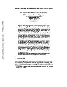
may not be accurately localized in images, and hence, 3D depths may not be recovered very accurately either. As can been see in figure 2, the simulation result shows a relatively flat landscape. When there is no error in 2D positions and 3D depths, indeed it is true that planar surfaces give zero H T F +F T H. But the value of H T F + F T H quickly jumps up and flattens out even with a small amount of noise added. Worse still, with large noises (or when the object is not planar), the error is about the same as the small noise cases. This means that planar surfaces can easily be identified as non-planar and vice versa. This is a disappointing observation because with noise perturbation we cannot distinguish non-planar cases from planar ones. Therefore, we directly compute the depth information of all these vertices through light-path triangulation and evaluate how close they can fit on a plane in the 3D space.
Fig. 2. The Frobenius norm of H T F + F T H
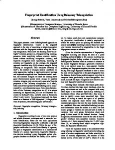
In figure 3, we illustrate this concept by using one example that involves only the minimum number of points. A, B, C, and D are four points in the 3D space and A� , B � , C � , and D� are their projections. Let us assume A� B � C � and B � C � D� are two adjacent triangles determined by Delaunay triangulation. The solid triangle ABC represents the plane defined by points A, B and C in the �
3D space. Its plane normal is NABC . To compute plane homography, we need at least four points, which means at least two triangles should be merged into a larger polygon. What we would like to know in this example is whether point D also lies on the plane ABC or not. Equation (4) describes how we test planarity in the 3D space. What this equation says is that if point D is very close to the
Lecture Notes in Computer Science �
�
7
�
plane defined by points A, B and C, vectors AD, BD and CD will be almost �
perpendicular to plane normal NABC .
Fig. 3. Example of planarity testing
�
�
�
�
�
�
max(| NABC · AD |, | NABC · BD |, | NABC · CD |) < threshold
(4)
Once the planes are detected and homography matrices are calculated, point correspondences in the planar regions can be easily determined by equation(1).
4
Optimization
The final step of our method is to optimize the stereo matching results with the help of dynamic programming (DP). The difference between the conventional DP approaches and our method is that we have already established many reliable point correspondences through planar homography constraints. These correspondences can serve as the ground control points (GCPs) and help stabilizing the stereo matching results. It has also been proven that the GCPs can significantly reduce the computational cost of DP [5]. In order to tolerant some noise and imprecision in localizing GCPs, GCPs are allowed to undergo a small amount of movement during the optimization process. Originally the total disparity range when processing images taken by a single camera will be [−W, W ] where W is the width of the rectified images. Unlike images shot by a pre-calibrated stereo rig that have only positive disparity values, images produced by a rectification program often have both positive and negative disparity values [1, 2]. Searching point correspondences with a large search range
8
Authors Suppressed Due to Excessive Length
is computationally expensive and error-prone. Therefore, we use the GCPs to further improve the speed by determining the disparity search range.
5
Experimental Results
Two-view 3D reconstruction results of three different data sets are presented in this section. In each data set, one gray scale input image, the computed depth map, and 2D views of the constructed 3D models are shown in figure 4. Our method works well on both indoor and outdoor scenes. We also apply the proposed method in our Colon-CAD project [10] to improve the accuracy of the model building process. Figure 4(c) depicts images of a colon acquired by an endoscope where a small camera is mounted at the tip. These images depict a diverticulum, an abnormal air-filled outpouching of the colonic wall, which may lead to infection and surgery may be needed. Using the structure-from-motion framework, we were able to successfully identify this type of structures. Medical images in general are much more challenging than indoor or outdoor data because tissue colors are very similar. Hence, the depth map in figure 4(c) is noisier than the other two depth maps. However, with the help of all anchor patches that computed by our method, the depth map of medical data does capture the important structure of the diverticulum (the circled area). Table 1 presents the timing comparison results between the proposed method and the traditional DP method. Both original and rectified image sizes are provided here. These two images sizes will be similar when the camera movement is roughly a sideway motion. The third column in this table shows estimated disparity ranges. The importance of this estimation is especially clear in the medical data set where rectified images are large while the actual disparity range is very small due to a relatively flat 3D structure. By limiting the search range, a significant amount of computation can be saved. The last two columns are numbers of seconds required to perform stereo matching using our method and the traditional DP method. In column Tri.+DP, we divide the computational time into two part—the preprocessing time where both Delaunay triangulation and homographies are computed and the DP optimization time. The listed DP optimization time in the last two columns include running time of computing pair-wise pixel similarity which is essential in real applications but not considered in many stereo papers when reporting the time required. As can been seen in table 1, the computational cost spent on preprocessing which depends on the number of features (Feature# in the fourth column) we detected is almost negligible comparing to the time saved from the DP procedure. This experiment was performed on a laptop computer with Intel Core2 2.00 GHz Duo processor T7200.
6
Conclusion
We propose a simple method to stabilize stereo correspondence computation. Scenarios where two input images are acquired by a single camera are considered.
Lecture Notes in Computer Science
9
(a)
(b)
(c) Fig. 4. Experimental results. (a) Indoor data (b) Outdoor data (c) Medical data
Table 1. Timing comparison Data
Image Size (Orig./Rect.) Disp.
Indoor 308 X 231 / 322 X 265 Outdoor 426 X 568 / 435 X 581 Medical 660 X 560 / 853 X 890
Feature# Tri.+DP (sec.) DP (sec.)
[-7, 51] 208 [-97, 4] 1836 [-3, 26] 74
0.04+0.45 0.25+2.74 0.02+1.67
15.56 58.98 424.37
10
Authors Suppressed Due to Excessive Length
Reliable SURF features are first detected for camera motion inference and for Delaunay triangulation. Instead of using individual triangles in the Delaunay partition and assume that 3D surfaces viewed through these triangles are locally planar, we combine adjacent triangles and test planarity hypothesis in the 3D space explicitly. Once planes are identified, point correspondences within these planar areas can be easily determined through homographies. All these point correspondences serve as anchor points in the final stereo optimization procedure. To the best of our knowledge, we are the first group to impose continuity constraint on stereo matching by examining planarity hypothesis in 3D space with the help of Delaunay triangulation and planar homographies. Three different types of data, including medical data, are presented in our experimental results. These results show that our method not only can stabilize the reconstruction results but also can significantly speed up the stereo matching process. The speed gain over the traditional DP method is obtained by automated disparity range determination as well as pre-assigned anchor points from the planar homography constraints.
References 1. Pollefeys, M., Koch, R., Gool, L.V.: A simple and efficient rectification method for general motion. In: Proceedings of International Conference on Computer Vision. (1999) 496–501 2. Hartley, R.I.: Theory and practice of projective rectification. International Journal of Computer Vision 35 (1999) 115–127 3. Brown, M.Z., Burschka, D., Hager, G.D.: Advances in computational stereo. IEEE Transactions on Pattern Analysis and Machine Intelligence 25 (2003) 993–1008 4. Scharstein, D., Szeliski, R.: A taxonomy and evaluation of dense two-frame stereo correspondence algorithms. International Journal of Computer Vision 47 (2002) 7–42 5. Bobick, A.F., Intille, S.S.: Large occlusion stereo. International Journal of Computer Vision 33 (1999) 181–200 6. Gong, M., Yang, Y.H.: Fast stereo matching using reliability-based dynamic programming and consistency constraints. In: Proceedings of the 9th IEEE International Conference on Computer Vision. Volume 1. (2003) 610–617 7. Hartley, R.I., Zisserman, A.: Multiple View Geometry in Computer Vision. Second edn. Cambridge University Press (2004) 8. Bay, H., Tuytelaars, T., Gool, L.V.: Surf: Speeded up robust features. In: Proceedings of the 9th European Conference on Computer Vision. Volume 3951 of part 1., Springer LNCS (2006) 404–417 9. Li, P., Farin, D., Gunnewiek, R.K., de With, P.: On creating depth maps from monoscopic video using structure from motion. In: Proceedings of 27th Symposium on Information Theory in the Benelux. (2006) 508–515 10. Koppel, D., Chen, C.I., Wang, Y.F., Lee, H., Gu, J., Poirson, A., Wolters, R.: Toward automated model building from video in computer assisted diagnoses in colonoscopy. In: Proceddings of the SPIE Medical Imaging Conference. (2007)