Stable Infrastructure-based Routing for Intelligent Transportation Systems Gubran Al-Kubati1, Ahmed Al-Dubai2, Lewis Mackenzie1, Dimitrios P. Pezaros1 1 School of Computing Science, University of Glasgow, UK e-mail:{
[email protected], lewis.mackenzie|
[email protected]} 2 School of Computing, Edinburgh Napier University, UK e-mail:
[email protected] Abstract-- Intelligent Transportation Systems (ITSs) have been instrumental in reshaping transportation towards safer roads, seamless logistics, and digital business-oriented services under the umbrella of smart city platforms. Undoubtedly, ITS applications will demand stable routing protocols that not only focus on Inter-Vehicle Communications but also on providing a fast, reliable and secure interface to the infrastructure. In this paper, we propose a novel stable infrastructure-based routing protocol for urban VANETs. It enables vehicles proactively to maintain fresh routes towards Road-Side Units (RSUs) while reactively discovering routes to nearby vehicles. It builds routes from highly stable connected intersections using a selection policy which uses a new intersection stability metric. Simulation experiments performed with accurate mobility and propagation models have confirmed the efficiency of the new protocol and its adaptability to continuously changing network status in the urban environment. Keywords- VANETs, Routing, Inter-vehicle communication, Roadside Units, Carry-and-forward, Geographic forwarding, Smart city.
I. INTRODUCTION The Vehicular Ad hoc Network (VANET) has emerged as a strategic component in Intelligent Transportation Systems (ITSs) that aim at helping drivers on the roads by anticipating hazardous events or avoiding congested traffic areas. Recent research has placed a strong emphasis on novel VANET design architectures and implementations aimed at delivering more efficient ITS applications. Among these mooted applications are: parking discovery; fleet management; ITS local electronic commerce; vehicle software/data provisioning and update; map/content/media downloading; and web browsing. Clearly, most of these applications require coordination between vehicles and road-side infrastructure, and a robust unicast/anycast routing protocol that fully integrates the infrastructure (represented by Road-Side Units (RSUs)) [1, 2]. Moreover, recently, there has been interest to expand the usage of RSUs beyond providing services and towards supporting routing [3-7] with the aim of enhancing scalability and mitigating the overhead a location service places on geographic routing. Clearly, paths towards nearby RSUs are more frequently requested than those towards other vehicles, since RSUs are the main service providers/directories and the vehicles enabler to communicate with distant peers. Hence, enabling vehicles to maintain proactively routes towards the most central nodes on the network (i.e. RSUs) whilst seeking on-demand other
less important nodes is expected to speed-up route building and maintenance while keeping the administrative overhead to a minimum. In urban environments, obstacles such as high buildings hinder message propagation, and growing shadowing and multipath effect on radio waves, making communication only possible when vehicles are in line-of-sight or few meters away from intersections (i.e., near-line of sight [8]). Packets are, therefore, routed towards the destination through successive roads joined by intersections which are considered as the main gateway for packet forwarding. Some earlier work on urban VANETs, such as RBVT-R [9], builds routes of connected roads. When an intersection has a low vehicle population, RBVT-R tends to reinitiate the route discovery process resulting in longer delay and extra overhead. TrafRoute [4] is an infrastructure-based routing approach that differently limits packet forwarding to intersections, so that a route is discovered only if the intersections are populated. RBVT-R and TrafRoute build such ‘loose’ source routes, likely experiencing frequent route breakages leading to increased losses and control overhead. Furthermore, when the number of vehicles increases at busy periods, long queues at intersections with traffic lights are formed. When this happens, the stability of routes using these intersections increases, however, data traffic congestion increases, thus leading to enhance the total end-toend latency. Given these considerations, this paper presents SIRP, a novel Stable Infrastructure-based Routing Protocol, which integrates features of both reactive and proactive routing schemes. In SIRP, beacons which RSUs generate are multihop broadcasted collecting the routing information to enable vehicles to maintain proactively routes to those RSUs, whilst vehicles reactively discover routes to nearby vehicles. Furthermore, SIRP relies on an innovative technique to construct high stable routes of successive intersections. Rather than using the vehicle density as a metric to measure the road’s multihop connectivity, SIRP considers the number of vehicles moving towards intersections as an intersection stability metric. This is because the latter is a better measure for the intersection ability to keep providing stable and reliable connections. Thus, this paper introduces a new routing strategy that uses the intersection stability metric to select more stable routes whilst satisfying an application’s QoS requirement. The rest of the paper is organized as follows. SIRP is presented in Section II. Section III discusses the simulation results, and Section V concludes the paper.
5004
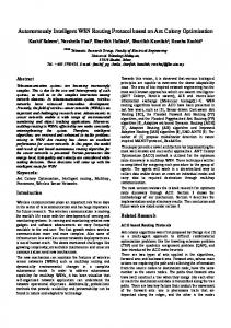
II. THE PROPOSED PROTOCOL SIRP SIRP is a geographic routing protocol for urban VANETs which exploits the fact that vehicles demand connections to RSUs at higher recurrence rates than directly to other vehicles, so that maintaining fresh routes to nearby RSUs is more important. It aims to allow individual vehicles proactively to build and maintain routing table entries for RSUs while searching for other vehicles only on-demand. To achieve this, it builds routes of successive intersection IDs that need to be traversed in order to reach the destination, and it weighs each intersection’s capability to forward packets using an intersection stability metric. As position-based routing, SIRP requires that each participating vehicle is equipped with both a positioning system (GPS) and a navigation system with a digital map from which it knows in advance attributes of all roads and intersections in the local road network at any given time. Intersection attributes include ID, geographic coordinates, IDs of neighbouring intersections, and the number with the width of all joined road lanes. Additionally, vehicles can localise neighbouring vehicles on road layouts. SIRP includes two functional procedures: Registration and Localization process and Route Discovery and Maintenance. It assumes that, an adequate number of RSUs are distributed in the road topology network, over any area of interest (e.g. a city). Each RSU has a unique ID (R ) and is fully connected by a wired/wireless network. Each is responsible for sending a periodic beacon called a Service Advertisement (SA) message which is a multi-hop broadcast after gathering routing information on each hop. Upon receiving these advertisements, each vehicle determines its corresponding RSU, to register with and also update its location. In this way, the size of RSU’s service area is adapted according to the state of network, rather than using the fixed areas in Ref. [4-6]. To facilitate sending packets to remote vehicles, the RSUs maintain, via the backbone network, a shared Distributed Hash Table (DHT) indexing the vehicle associations, as discussed in [4]. Therefore, each packet that is relayed via the infrastructure will be re-routed to the RSU to which the destination is currently registered. In contrast, a vehicle builds routes towards adjacent vehicles using a reactive route discovery process. In the next subsections, we explain in depth the operations of SIRP. A. Vehicle Classification In real cities, the average road length is less than the default transmission range of IEEE 802.11p (i.e. 400m): the average road length of the New York City is about 125m [10]. Accordingly, most of the road intersections (with/ without traffic lights) are within radio range of each other. A vehicle at the centre of a given intersection typically has a Line of Sight (LoS) to vehicles at neighbouring intersections. Furthermore, it is known that vehicles tend to create dense clusters at traffic lights. SIRP therefore gives vehicles at any intersection (denoted by ) the highest priority to act as packet forwarders. At the same time, it limits the number of vehicles to those close to the centre of each junction to control the number of forwarding vehicles whilst maintaining overall network connectivity. To do this, each vehicle maintains a fresh neighbours table using mandatory broadcast beacon messages,
Fig 1. Vehicles classification in an urban scenario
called Cooperative Awareness Messages (CAMs). SIRP complies with European standards (ETSI [11]), and CAM messages include all required information (e.g., vehicle ID, geographic coordinates, velocity, direction, etc.). According to the closest intersection’s attributes and the current and average number of neighbours, each vehicle then inde: pendently computes the reference distance, 1
1
(1)
where is the minimum radius of a circular area covering the centre of the intersection, as shown in Fig. 1. If a vehicle finds that its distance to the closest intersection centre is less , it elects itself as a member of . In this way, the than more vehicles around the intersection, the smaller the number of vehicles that join . Note that a long or curved road may need several hops to traverse, thus requiring the placement of additional virtual intersections along its length. If a vehicle moving towards an intersection receives CAM beacons from either vehicles at the intersection or vehicles that are heading towards that intersection from other notinline streets, it considers itself as a member of the set of nearor are in . intersection vehicles, . Vehicles not in Each vehicle uses a Status Flag (SF), an extra two bit field, in its own CAM packet, to inform neighbours of its current , , or . Each vehicle can determine membership state: the intersection a CAM transmitting vehicle belongs to using the location and direction of velocity vector. In addition, a 3bit field, denoted by Penetration Index (PI), is appended to the CAM. With respect to a vehicle, PI equals the number of distinct neighbouring intersections that the vehicle’s transmisvehicle belonging to sion can reach: it has at least one or those intersections in its neighbours table. On the other hand, vehicle, PI equals the number of intersection legs that for a vehicle’s transmission can reach: it has at least one vehicle at those legs. B. Route Selection Policy SIRP uses a novel metric called Intersection Stability ( ) to measure the stability of source routes of successive intersections in urban scenarios. Following the example shown in Fig. 2, we are going to describe the intersection stability concept. When receives a CAM message from or , it declares its status and generates a new CAM message. SIRP considers only vehicles that are moving towards the intersection as nearintersection vehicles in order to increase the confidence that a
5005
Using the aforementioned policy leads to two issues: (a) in a dense network, the highest stability route will be the route with the maximum congestion level; and (b), during the validation experiments, we found that the probability of the route breaking increases with the number of unstable intersections along the route. Consequently, the route set is divided into two includes highly stable routes; while the other subsets: routes are sorted according to the existence of the multiple . Therefore, we improve route seunstable intersections in lection policy as follows:
Fig. 2 Intersection stability Example
vehicle will be able to retransmit the packet through the intersection in all directions. At the same time, it will refer to the in the near fuexpected number of vehicles that will be in ture. Therefore, SIRP makes near-intersection vehicles comand , and once inside the intersection pute the size of area, they recognize , the sum of the sizes of and V : this value will determine the capacity of the intersection to carry stable connections at the current time. , of the multi-hop connectivity Definition: The stability, of the ith intersection approximately equals the number of ve, that can provide expected high hicles ( ’s and ’s), stable connections through the intersection; ≅
(2)
, the stability, At the time of the decision-making, can be determined approximately as follows:
, (3)
is the initial number of vehicles V and V at the where can be approxigeneration time, , of the RREQ packet. mated further using:
(4)
where refers to the average expected value of changing rate which takes into account the short-term variation incurred by changes in status of neighbouring vehicles around the intersection area. By using the Round Trip Time (RTT), at the destination determines approximately the expected the time of reception in the ith intersection, . This value will refer to the expected intersection 0, the intersection will be still able to stability. As long as forward transmitted packets. To select the most stable route, a naïve approach is to select the route with the maximum value of the minimum intersection stability along the route. When a vehicle has a packet to send to another vehicle, it initiates the route discovery process by broadcasting a RREQ message. Upon reception of a RREQ, each intermediate vehicle checks its status. If it is a vehicle, it will append and for the out-going intersection ‘i’ along the route. The stability of route ’j’ denoted by , can be computed as follows: min
∀
∈
(5)
Upon reception of multiple RREQs, the destination may select a best candidate route ‘k’ from the candidate route set “U” according to:
∀
max
∈
(6)
min
∈
min
∈
, ,
∅ (7)
where is the packet trip time, which is the duration time between the generation time of the RREQ packet and the reception time of the RREQ at the destination, and UI is the number of the unstable intersections in the route. By receiving multiple RREQs, the destination will employ this route section policy to select the proper route according to the real-time network situation: either the minimum-delay and lowestcongested route in a dense network, or the most stable route in a sparse network. Even if the stability of the intersection is zero at the RREP reception time, the intersection may be still able to forward the packets by vehicles that for instance, just leave the intersection area. C. Registration and Localization Processes In SIRP, each vehicle is allowed to select a suitable RSU according to the actual situation on the road. The assumption of dividing the city-wide network into fixed sectors (RSUs’ extended service areas) is relaxed. In [4-6], if the sector’s RSU fails (due to breakdown, congestion, or an empty RSU coverage area) or even if there is no suitable path, a vehicle that enters the service area of the failed RSU will not be able to reregister or receive packets intended for it until the problem is resolved. In SIRP, a vehicle is enabled to keep eavesdropping on periodic multi-hop broadcast beacons from RSUs in its vicinity, and then selects one as a corresponding RSU to which it has a relatively reliable, stable, and minimum-delay route. This will not only help vehicles to remain connected in a sparse network, but also mitigate congestion and balance the vehicles distribution among neighbouring RSUs in dense networks. Hence, a service advertisement mechanism is adopted in the registration and localization processes. Each RSU advertises its services by broadcasting a SA beacon message every seconds. Each such beacon includes the RSU’s ID, sequence number, time to live , field indicates the beatimestamp ( ), and PATH. The con’s hop limit. indicates the time at which the SA beacon is generated. PATH is the sequence of , , tuples of each intersection i along the beacon propagation path. Each beacon forwarder will add its intersection’s tuple to PATH, and decrease the . Note that, only vehicles are allowed to broadcast the SA beacon to limit the amount of overhead while selecting more stable routes. Upon receiving beacons from distinct RSUs, each vehicle, after selecting the most stable route to each RSU, proactively maintains a fresh route towards each RSU along with the beacon trip time delay, ,
5006
where . If a vehicle finds that it has a lower-delay stable route to a new RSU than to an old one, it considers re-registering with the latter and updating its location. To avoid a ping-pong effect, however, it does not do this immediately: instead, upon receiving few distinct beacons from different RSUs, it calculates the delay changing rate of over a specific period of time : the routes towards each ∑
,
0.5
(8)
where K indicates the number of received beacons during . less than the curIf it finds that a new candidate RSU has distinct beacons durrent one and receives at least 0.5 ⁄ ing , it re-registers with the new RSU using a modified RREP packet. To update its location, when a vehicle either finds a new robust minimum delay route to its corresponding RSU after or has no candidate forwarder in its neighbours table towards the last intersection in the previous route (i.e., it is no longer connected to this intersection), it waits for a new SA beacon from its registered RSU and then unicasts the modified RREP packet. It is worth noting that the destination is required to add the next intended intersection to the route in its RREP packet as well. This process does not produce significant overhead because it is adaptive to the level of vehicle mobility on the road, while it speeds up the connection to the infrastructure. RSUs maintain a list of registered vehicles with the entire route towards them, implying that a vehicle has a virtual location between the last two intersections in the route, or at least it is still reachable through one of the last two intersections in the route. In other words, a vehicle location here refers to its own reachable intersections instead of its own geographic coordinate. The difference between registration and localization is that the new RSU will inform the old RSU about the registration request in the registration process, where the registration request packet includes the old RSU’s ID. Therefore, the old RSU can in turn delete a vehicle from its location table. Note that, as long as a vehicle finds a proper route of successive intersections towards an RSU, this implies that other vehicles along this path will choose the same RSU for registration. In this way, the RSU’s extended service area is constructed by all vehicles which registered with that RSU, and this area is adaptive to the current network conditions. D. Route Discovery Since the registration and localization processes guarantee that all vehicles register and update their locations (entire routes) with RSUs, the route discovery process is modified to reap the benefits of maintaining proactive routing. Vehicles keep and maintain fresh routes towards RSUs using beacons, whereas RSUs record complete continuously updated routes towards registered vehicles. Indeed, reducing reactivity in favour of proactivity will improve performance as long as most data traffic passes through RSUs. When a vehicle has a packet to send, there are two scenarios: 1) the destination is on the Internet or its corresponding RSU; 2) the destination is a vehicle. In the first scenario, the vehicle picks up a fresh route from the RSU list and starts to unicast packets to the RSU. It is possible that a source vehicle will receive new beacons from a RSU during the on-going session. In that case, the source may use a
new route if the new route is more appropriate or the current one is impaired. This scenario also applies if the source is a RSU that includes the registered vehicle destination. In the second scenario, a source vehicle computes the maximum delay T towards the corresponding RSU. T is the maximum beacon delay during each T . Afterwards it broadcasts a RREQ message with a time-to-live outside TTL ; TTL
T
T
.
(9)
After the source vehicle broadcasts the RREQ packet, a vehicle is allowed to forward the packet only if it is in and the packet has not been passed through the same intersection before. Furthermore, if the vehicle in is registered with the same RSU as the source, it will simply re-broadcast the RREQs. On the other hand, if it is registered with another RSU, it should re-broadcast the RREQ only if TTL Current Time T . To facilitate this process, RREQ packets always include the requesting vehicle’s corresponding RSU ID. Also, each RREQ forwarder appends the , , tuple of the current intersection. This approach ensures that vehicles registered with a neighbouring RSU, which is much closer to the source vehicle than the existing correspondent, can receive a copy of the RREQ packet via an entirely ad hoc multi-hop communication pattern along with a mixed communication mode. T can be adaptively selected according to prior knowledge of the destination location; however, for the sake of simplicity, here we set T 0.5 T 1.5 T . (TTL If the source’s RSU receives the RREQ and recognizes that the destination belongs to another RSU, it will forward the packet to the destination RSU; otherwise the source’s RSU discards the packet. If the destination’s RSU has a fresh route towards the destination, it will reply with RREP directly; otherwise it re-broadcasts the RREQ packet in its service area. Once the destination vehicle receives multiple RREQs, it determines the most appropriate route selected by the aforementioned route selection policy. It subsequently computes the next intended intersection according to its own current trajectory and velocity vector, and appends this next intended intersection to the inverse intersection sequence of the selected path if the next intended intersection is not included. It then issues the RREP packet and it sends the packet back to the source vehicle. If the source vehicle does not receive the RREP packet after a timeout period, a new route discovery is initiated. E. Data Forwarding and Route Maintenance Upon receiving RREP, the source starts sending the data packets, after adding a small header containing the reverse intersection sequence contained in RREP. At each unicast packet forwarding step, if the vehicle forwarding the packet has a number of vehicles at the next intersection on the path, it selects the one with the highest penetration index (PI) vehicle as a next hop forwarder. If it has none, it selects the with the biggest PI; otherwise it chooses the farthest vehicle along the path. If the vehicle carrying the packet has not any candidate forwarder along the path, it sends the route error (RERR) packet back to the source. However, it is likely that RERR packet cannot reach the source vehicle due to the route
5007
TABLE I SIMULATION SETUP Simulation area 1200m × 1200m Simulation time 800s Number of RSUs, vehicles 3, 200 ~ 800 Vehicle speed 10 ~ 20 m/s Transmission Range 400m Data Transmission rate 6Mbs Number of CBR sources 20 CBR rate 2 Pkt/s Data packet size 512 bytes 0.5sec , 2sec 10sec impairment. Therefore, during an on-going session, SIRP, checks the validity of the route by periodically issuing a Route Check (RCHECK) packet along the path. Then, the destination vehicle will reply with a RCHECK reply packet. Also, the next intersection to the route is also added to the RRCHEK packet and its reply packet. This should keep the control overhead as low as possible and reduce data packet loss rate. III. PERFORMANCE EVALUATION This section presents the evaluation of SIRP under simulated urban conditions. Simulation experiments are performed using ns-2 with the VanetMobiSim mobility generator to build a real urban scenario from the south part of Manhattan island centered on (40.7377 , 73.9882 ), with an area 1.2 km , as shown in Fig. 3. The average street length is circa 120m and there are traffic lights at all intersections. We conduct our experiments with different numbers of vehicles, repeating each at least 30 times and calculating average values. The propagation model parameters are similar to that of WINNER B1 model which takes into account the log-normal shadowing and LOS/NLOS visibility between vehicles on the urban environment [12]. In addition, IEEE 802.11p is used as MAC/PHY layer with the default values according to ETSI standards [13]. We randomly select a source and a destination from the input vehicles, and the destination is selected randomly and it could be at any location on the map. The other simulation parameters are summarized in Table I. SIRP is evaluated against RBVT-R, TrafRoute, and FRHR [14] routing protocols. RBVT-R is one of the earlier suggested routing protocols for urban VANETs that builds source routes of successive connected roads. However, it does not consider that the main cause of the route failures is the empty intersections. If a vehicle forwarding an RREQ that has already left an intersection, the data packets may not find suitable forwarders through that intersection. Thus, the scheme builds low stability routes that are highly breakable as clearly shown in Fig. 4, and it tends to reinitiate the route discovery frequently, as shown in Fig. 5. TrafRoute constructs routes from intersections and outperforms RBVT-R, as shown in Fig. 4 and Fig. 5. It uses a superior forwarding technique that obviously reduces the broadcast redundancy in urban scenarios. TrafRoute prefers minimum-delay routes with fewer intersections even though there may not be enough vehicles around
these intersections to extend the route life time. FRHR follows the same concepts as TrafRoute, except that FRHR utilizes the registration and location procedure by which it maintains proactivity routes between vehicles and RSUs; using these, leads to a lower number of broken routes and few RREQ packet broadcastings if there are some source-destination pairs belonging to different RSUs. In this case, vehicles can update their routes towards RSUs on-the-fly, and vice versa. When the number of required interfaces to the infrastructure or to distant vehicles increases the advantage of proactive route maintenance towards RSUs becomes more and more apparent. Furthermore, with higher number of vehicles in the network, the number of broadcast RREQs grows in RBVT-R. It is worth indicating that other protocols are more scalable because they limit the packet forwarding to vehicles residing near the intersections. Trafroute and FRHR prefer minimumdelay routes with fewer intersections, whereas SIRP uses a more flexible route selection policy that takes into consideration the importance of weighing the intersection capability for multi-hop connectivity: this increases route stability in low and medium-density vehicle networks while avoiding selecting highly congested intersections in dense networks. Fig. 6 shows the total control overhead to received data byte ratio. Generally, the ascending trend of the overhead ratio is attributed by the increased number of CAM messages produced while the number of CBR sources is fixed. Although RBVT-R is beaconless, CAM broadcasting in VANETs is essential and irreplaceable. Other protocols modify the CAM packets adding few extra bits. FRHR and SIRP use additional control packets in the registration and localization procedure; however, the increased demand for routes through RSUs and improved routes stability outweighs the influence of this additional overhead. Fig. 7 shows the data packet delivery ratio. Apparently, SIRP and FRHR outperform TrafRoute and RBVT-R, particularly in sparse networks. This result is due to the more rapid response of vehicles to changes in network connectivity. A vehicle re-registers with a RSU to which it has a connected path rather than maintaining its association to a disconnected RSU in TrafRoute and RBVT-R. As depicted in Fig 7, the performance of TrafRoute and RBVT-R gradually converge to that of FRHR as the network gets denser. However that is still achieved by involving multiple routes requesting which caused increased end-to-end delay, as shown in Fig. 8. As long as each source-destination pair is composed of vehicles at random distances from each other, enough data traffic will pass through RSUs towards these vehicles. In FRHR and SIRP, the destination RSU can send packets intended for a registered destination directly, whereas paths among vehicles and RSUs are built in a proactive manner. Consequently, the route setup time is substantially reduced as well. Furthermore, SIRP avoids selecting low vehicle-populated intersections as possible to build highly stable routes which, in turn, enhance its performance in low-to-medium populated networks. It prefers long-distance, long-lasting routes over shorter but more transient alternatives that would re-initiate the route discovery much sooner. In dense networks, SIRP selects the lowest congested route, taking into account that the route should be sustainable. Overall, SIRP has displayed superiority over its con counter-
5008
Fig. 3. Roads Network from the South Part of Manhattan Island, including 3 RSUs
Fig. 4. Number of routes breaks versus Number of Vehicles
Fig. 5. Number of produced RREQ Packets versus Number of Vehicles
Fig. 6. Overhead versus Number of Vehicles.
Fig. 7: Packet Delivery Ratio versus Number of Vehicles.
Fig. 8: End-to-End Latency versus Number of Vehicles.
parts and it adapts well to the continuously changing network status characteristics of the urban environment. IV. CONCLUSION AND FUTURE WORK This study proposes a routing protocol, SIRP, for fast infrastructure access and efficient V2V communications. SIRP uses the RSUs, connected through the wired backbone network, to act as registration servers for vehicles. SIRP proactively builds routes through successive intersections between vehicles and RSUs, and reactively among vehicles. This returns a fast connection set-up time with the most important nodes in the network, namely the RSUs. Moreover, SIRP takes route stability into account to resolve the problem of frequent breaks in urban VANETs as clearly seen in the simulation experiments. This is exhibiting the lowest end-to-end latency and the highest delivery ratio over varying vehicular traffic. For future work, the integration of the new scheme with a delay-tolerant solution across vehicle access to other available networks will be investigated.
REFERENCES [1] Taysi, Z.C.; Yavuz, A.G., "Routing Protocols for GeoNet: A Survey," IEEE Transactions on Intelligent Transportation Systems, vol.13, no.2, pp.939-954, June 2012. [2] Karagiannis, G.; Altintas, O.; Ekici, E.; Heijenk, G.; Jarupan, B.; Lin, K.; Weil, T., "Vehicular Networking: A Survey and Tutorial on Requirements, Architectures, Challenges, Standards and Solutions," IEEE Transactions on Communications: Surveys & Tutorials, vol.13, no.4, pp.584-616, 4th Quarter 2011. [3] Borsetti, D.; Gozalvez, J., "Infrastructure-assisted geo-routing for cooperative vehicular networks," IEEE Vehicular Networking Conference (VNC), 2010, pp.255-262, 13-15 Dec. 2010.
[4] Frank, R.; Giordano, E.; Cataldi, P.; Gerla, M., "TrafRoute: A different approach to routing in vehicular networks,", In 6th IEEE International Conference on Wireless and Mobile Computing, Networking and Communications (WiMob), pp.: 521-528, 11-13 Oct. 2010 [5] Khaleel Mershad, Hassan Artail, Mario Gerla “ROAMER: Roadside Units as message routers in VANETs”, Elsevier Ad Hoc Networks, vol: 10, pp.: 479–496, 2012. [6] Jang-Ping Sheu; Wei-Kai Hu; Bol, R.E., "A registration system for aiding in localization and routing in hybrid VANETs," 12th Int. Conference on ITS Telecommunications (ITST 2012), pp.:694-699. [7] Jang-Ping Sheu; Chi-Yuan Lo; Wei-Kai Hu, "A Distributed Routing Protocol and Handover Schemes in Hybrid Vehicular Ad Hoc Networks," IEEE 17th International Conference on Parallel and Distributed Systems (ICPADS 2011), pp.: 428-435, 7-9 Dec. 2011. [8] T. Mangel, O Klemp, and H. Hartentein, “5.9GHz inter-vehicle communication at intersections: a validated non-line-of-sight path-loss and fading model,” EURASIP J. on Wireless Communications and Networking, 2011. [9] Nzouonta, J.; Rajgure, N.; Guiling Wang; Borcea, C., "VANET Routing on City Roads Using Real-Time Vehicular Traffic Information," IEEE Transactions on Vehicular Technology,vol.58, no.7, pp.3609,3626, 2009 [10] M. Fogue, P. Garrido, F. Martinez, J Cano, C. Calafate, P. Manzoni, “Evaluating the impact of a novel message dissemination scheme for vehicular networks using real maps,” Transportation Research Part C, vol: 25, p.p: 61–80, 2012. [11] COMeSafety consortium, "031: European ITS Communication Architecture: Overall Framework Proof of Concept Implementation", COMeSafety European Specific Support Action Public Deliverable, Dec. 2009 [12] WINNER consortium. Draft D1.1.2. WINNER II channel models. WINNER European Research project Public Deliverable, Sept. 2007 [13] ETSI TS 102 687, Intelligent Transport Systems (ITS); Decentralized Congestion Control Mechanisms for Intelligent Transport Systems operating in the 5 GHz range; Access layer part, Draft v1.1.1, July 2011. [14] Al-Kubati, G. ; Al-Dubai, A. ; Mackenzie, L. ; Pezaros, D. " Fast and Reliable Hybrid routing for Vehicular Ad hoc Networks", In 13th International Conference on ITS Telecommunications (ITST 2013), p.p: 20- 25, 5-7 Nov. 2013, Tampere, Finland.
5009