The best of practice techniques. (e.g., [2][3]) have become dated, and the best minds in the business are scrambling to come to grips with the reality of systems ...
Standards-Based Software Testing in a Net-Centric World
KC Morris David Flater Manufacturing Systems Integration Division National Institute of Standards and Technology Abstract
while not compromising throughput. Instead of building systems from scratch, practitioners are seeking to be able to integrate off-the-shelf software components into a coherent system with minimum expense on custom programming. To do this, they need to be able to upgrade or replace individual components without breaking the system. Manufacturers are increasingly looking to open systems and standards[5][6] as a possible solution, and this, in turn, has led to focused projects at the National Institute of Standards and Technology (NIST). NIST recently began investigating test methods for the new breed of integrated systems. We, in the Manufacturing Systems Integration Division (MSID), are focusing more specifically on the testing of interaction-driven manufacturing systems (TIMS). Interaction-driven manufacturing systems are those composed of multiple software components in which the interactions between those components are automated. Automation is typically achieved through the definition of program interfaces, both standard and proprietary, which allow the components to directly interact without the need for human intervention at every step along the way. The variety of infrastructures, applications, and system architectures exhibited by these systems poses a challenge to the development of common test methods. To support the effort we have studied specifications for manufacturing systems integration and approaches to testing that are relevant to those specifications.[7] This paper describes our conclusions based on the study and provides a description of the issues surrounding testing of systems in this context.
Automation for product development and manufacturing is changing to take advantage of the recent expansion of the Internet and the computing technologies supporting it. These processes are becoming more software dependent, and the software used is becoming more modularized, allowing for the creation of customized systems consisting in large part of pre-existing components distributed across a network. This combination of factors leads to considerable flexibility for manufacturing systems, but not without a cost. The reliability of those systems is uncertain given the lack of experience in how to test such systems. To address this need, the National Institute of Standards and Technology’s Manufacturing Systems Integration Division has undertaken a study of how to test “interaction-driven manufacturing systems.” This paper presents the results of a study of the problems involved in testing these new systems, reports on factors which influence the testability of the systems, and outlines approaches to testing.
1. Introduction Software systems are built differently today than they were a decade ago. The approach of testing traditional systems using the sequence of unit, integration, and system testing[1] is well-established; however, what we once called “systems” are now single components in larger, integrated, net-centric systems, and our testing techniques are in need of revision. The best of practice techniques (e.g., [2][3]) have become dated, and the best minds in the business are scrambling to come to grips with the reality of systems that, using traditional terminology, would have to be called “large and complex distributed systems of systems.”[4] Systems of the past were designed to optimize throughput, but today’s systems are being designed for flexibility
2. Testing The specifications considered in our study fall into three categories: • infrastructures used to connect the system, • applications used in the system, and • the operation of the system itself.
1
Each category presents unique difficulties. A wide variety of different infrastructures is available to connect systems. Requirements for components in these integrated systems are often not well specified since the components are designed as stand-alone units. The systems themselves are subject to instability due to nondeterministic interactions in the systems. In the following pages we discuss testing considerations for system components, both infrastructural and specialized applications, and for a system itself.
frastructural standards include programming languages, scripting languages, protocols for shared file systems such as NFS/RPC,1[12][13] messaging languages such as Manufacturing Message Specification,[14][15] UNIX-style pipes, and sockets. These infrastructures allow applications to interface in a controlled, deterministic manner. Net-centric infrastructures, such as CORBA/IDL[16] and Java’s Remote Method Invocation[17] and JavaBeans,2 enable invocation of remote processes and access to programs to be run locally, thereby supporting a looser coupling of systems.
2.1 Considerations for testing components Layering of components. In our study of interfaces for specialized components in manufacturing systems we found that they relied on a variety of infrastructural components. The more traditional and the most common type of interface was specified as a software library in a specific programming language. However, the trend is for interfaces to be defined in tiers, where a binding to a programming language is the bottom layer and middle layers provide the location independence that helps in building net-centric systems. The number of tiers tends to increase as specifications are bound to already tiered infrastructures, such as is the case with the ISO Standard for the Exchange of Product Model Data3 (a.k.a. STEP, see below.) This layered approach is both good and bad news for testing. The good news is that the rigorous methods used to define and describe the interfaces can be leveraged in the development of test suites. The bad news is that the internal complexity of the interface is increased with each new tier. This complexity makes it difficult • to pinpoint what is actually relevant for testing purposes, • to develop tests that isolate aspects of the interface relative to the technologies used in each layer, and • to verify the executable tests against the specification. Testing of infrastructural components differs from testing of specialized components in that, for the most part, infrastructural components are not manufacturing specific and can be exercised by generic types of test suites. Generally speaking, infrastructures are most vigorously, thoroughly, and quickly tested for conformance to a specification through use rather than by any formal testing activity.
The first step in testing an interaction-driven manufacturing system is to identify the components of the system. These should be clear from the system architecture. The components in a typical manufacturing system will include several commercial off-the-shelf (COTS) products which may support open or proprietary interfaces. Components may be infrastructural or specialized and range from machine control devices through scheduling, inventory, and planning systems. Other components in the system will be custom built applications that interface with and bridge the gaps between these vendor-supplied products. Simple component diagrams are often used to illustrate the system architecture. More formal Architecture Description Languages (ADL)[8][9][10] are emerging. More detailed and formalized system models can also be constructed using aspects of the Unified Modeling Language (UML).[11] Traditional software architectures use a tight integration of subsystems based on shared libraries which are linked into run-time execution modules. In these systems the common infrastructure is the programming language. Dynamic linking (linking at run-time) is one step towards creating more flexibility in component-based systems. Even so, connections between components traditionally are reduced to file exchanges rather than direct interactions. Today’s net-centric world is not compatible with this traditional architectural style. In the net-centric world components not only run in separate execution modules but can also be on separate processors using different file systems. This distribution is forcing advances in system engineering and software standards to support more flexible integration of systems capable of direct interactions without tight coupling. Infrastructural specifications address the coupling between specialized components and provide a protocol (in the general sense) for the connections. Aspects of the connections can be tested for consistency and completeness in much the same way that a compiler tests a program for consistent use of a programming language. Traditional in-
1. Network File System/Remote Procedure Call. 2. Certain commercial equipment, instruments, or materials are identified in this paper to foster understanding. Such identification does not imply recommendation or endorsement by the National Institute of Standards and Technology, nor does it imply that the materials or equipment identified are necessarily the best available for the purpose. 3. The Standard for The Exchange of Product Model Data (STEP) is a project of the International Organization for Standardization (ISO) Technical Committee on Industrial Automation Systems and Integration (TC184) Subcommittee on Industrial Data (SC4).
2
When there is a formal testing activity it generally comes after the fact and is designed to differentiate multiple vendor products supporting the same specification and highlight those areas of inconsistent support so that they may be addressed. On the other hand, infrastructural components are integral to the testing of specialized component interfaces since the specialized components are based on the infrastructures. Many testing tools, and hence techniques, revolve around the use of a particular infrastructure. Additionally, the emerging layered infrastructures can be tested by harnessing with testing tools based on one of the underlying infrastructures. Indeed, test methods based on infrastructures are essential to managing the layers.
ISO standard provides a mechanism to change the state of a PDM system by changing the data on which it operates, whereas the OMG standard provides an interface to state changing operations which will in turn modify the data contained in the system. Other differences in the specifications include the infrastructures used. Applications using the ISO standard would access PDM systems using either C, C++, Java, directly or through IDL. Applications using the OMG standard would only have access through IDL. The TIMS project is currently investigating approaches to testing these systems in an integrated fashion. Approaches to testing. Conformance and interoperability testing are two different approaches to validating a component’s usefulness with respect to a specification.[21] The basic difference between the two is that the traditional conformance testing approach compares an implementation to the intention of a written specification, whereas the interoperability approach compares an implementation with other implementations. Conformance testing typically is approached as a systematic coverage of a specification while interoperability testing typically takes a scenario-based approached to choosing the tests. In both cases the differences discovered by the comparison is the result of the test. An advantage to conformance testing is that each implementation is compared to the same thing and to only one thing. Also, the breadth of coverage of a specification by a conformance test can be measured and redundant tests can be minimized. Finally, conformance tests can be developed independently from implementations of those tests. However, a criticism of this approach is that it can miss tests that are important in real world implementations and it can catch things that are irrelevant in the real world. The advantage of the interoperability approach is that by its nature the tests are targeted to reveal the very things that would cause problems in common use. Interoperability testing also has disadvantages. When differences do arise between implementations, the source of the problem is indeterminate. For interoperability testing to be most reliable an implementation should be compared with many other implementations, not just one, thereby dramatically increasing the effort required to perform the tests. Also, when a new implementation emerges, there is no mechanism in place to test it independently. Another round of interoperability tests would need to be conducted with all existing implementations. Finally, while interoperability testing is more certain to address problems which occur in common use, the less commonly used parts of a specification may not be exercised. In light of the complexity of interfaces defined for a netcentric world and the variability in approaches to testing, a practical approach must be taken. The complexity of the
A case study: Product Data Management. The ISO standard known as STEP specifies an interface to specialized components based on the older architectural style. Specifically, it provides a file format for the exchange of data between systems. This valuable standard is rich in specification of the application-specific semantics of manufacturing interfaces; researchers are struggling to define mechanisms to bring it into a net-centric world. The first resulting specification is a data access interface (a.k.a. SDAI)[18] that defines a layered infrastructure for a series of interfaces to interaction-driven manufacturing systems. The SDAI approach is based on a rigorous methodology which has not yet been fully exercised. To date, test techniques for specialized component interfaces have only been applied on individual components and we have found no activities to systematically reuse the methods on a variety of interfaces as would be possible by combining SDAI with STEP’s semantic definitions from a number of different application areas. For example, STEP contains definitions for product data management. When these definitions are mapped into SDAI which is then mapped into the Interface Definition Language (IDL)[16] (another infrastructural component), the result is an interactive interface to a Product Data Management (PDM) system suitable for use across a network but originally designed for more traditional styles of interaction. The Object Management Group (OMG)[19] produced a similar, yet different, interface, known as the PDM Enablers.[20] The PDM Enablers uses one of the same infrastructures, namely IDL, but defines a different style of interaction with the underlying system. More specifically, the PDM Enablers are used to initiate operations supported by PDM systems whereas the SDAI/PDM interface defines low level data access functions. These two specifications provide a good example of two different styles of interfaces to the same functional component, in this case a Product Data Management system. The
3
interfaces makes the idea of a comprehensive conformance test suite daunting, yet the rate of change for software products and the expense of conducting interoperability tests gives the results of those tests a short lifespan. Furthermore, components in manufacturing systems are often very complex pieces of software in themselves, so defining the tests and expected results can be a non-trivial problem. Often the best way to determine the expected results is by computing them. The result is a reference implementation of the specification. When testing using a reference implementation, results from an implementation under test are compared with the results obtained from the reference implementation under the same conditions.
tegration testing from system testing.[24] However, for our larger distributed systems, the only real differences between these tasks are the invasiveness of the testing and the types of faults that we hope to find in each stage. For the purposes of this discussion, then, we will not struggle to keep them separated, but assume that Brooks’ advice to “Add one component at a time” will nonetheless be followed in the software development process. Interactivity. Just as data flow diagrams can be used to identify data sources and sinks, a new kind of diagram can be used to identify sources and sinks for activity. Interactivity is represented by flows of activity; it is the activity of interacting, or the business of interaction. Interaction is more than just reaction; hence, interactivity is more than just the sending of messages. It represents a possible source of non-determinism in the system, which is a critical factor in the system’s testability. Flows of activity are used to show the sources of non-determinism and the ways that this non-determinism ripples through the system. By drawing an arrow representing activity flow in one of the following diagrams, we are saying that the component at the start of the arrow is perturbing the component at the end of the arrow in a partially or completely non-deterministic way. The specific way could be a data flow, a control flow, a message, an event, or something else — it does not matter. These activity flow diagrams therefore differ from data flow diagrams and similar diagrams because they contain information about the sources of non-determinism and the parts of the system that are affected by it.
2.2 Considerations for system testing While many specifications concentrate on individual software interfaces within a manufacturing system, the concern of end users of manufacturing software is whether the final integrated system performs as required. From both practical and formal perspectives, verifying correct behavior of the entire system is quite different from verifying the behavior of individual components. As Brooks observed, the system test is “unexpectedly hard,” and is often made harder by a lack of conceptual integrity between independently specified and/or developed components.[22] The risk and cost of system level problems only becomes greater as industry moves away from monolithic, proprietary solutions and instead assembles systems from open standard software components bought from completely different sources. The individual “components” that we are integrating today would have been considered “systems” at one time, so “integration testing” and “system testing” need to be understood in this new, larger context. Net-centric systems pose a special challenge because dynamic interaction between disparate components is much more sensitive to errors than is static file exchange. If two components disagree on a syntax issue for file exchange, we might be lucky enough to lose only a small part of the input; but if they disagree about a network interaction, it is almost certain to stop the show. Integration and system testing are therefore crucial to the reliability of net-centric systems. A publication from Rational Software Corporation[23] defines integration and system testing in such a way that problems like deadlocks and race conditions are expected to have been found during integration testing (much as functional faults are expected to have been found during unit testing), leaving only relatively “soft” problems to be found during system testing. This is consistent with a great deal of our own precedent which steadfastly separates in-
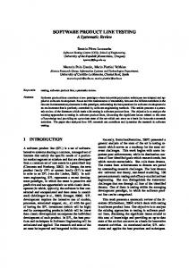
Browser (source) Browser (source)
Web server (sink) Browser (source)
Figure 1. Simple interactivity diagram In a classic client-server architecture such as that of the web-based system modeled above, all components are either sources or sinks of activity. Because they do not have complex dependencies on other components, sources and sinks can be tested as stand-alone systems by replacing the components on the other side of the interactions with a simple test harness.
4
The non-determinism in this system is that the arrival times of requests from browsers and the contents of those requests are random as far as the web server is concerned. Because web servers themselves are designed to be stateless, this would seem to be an insignificant observation. However, if we instead have a manufacturing system where orders for products and machine control commands are being entered through web interfaces, the activity coming from the web browsers may easily be sufficient to trigger timing-related failures in the system.
In Figure 3, the shop and workcell controllers each have their own thread of control and may initiate interactions at any time. When activity becomes cyclic as it has in this example, a new category of problems such as deadlocks, race conditions, and inconsistent world views is introduced. These problems have been explored extensively in network testing, but not so extensively for interaction-driven systems in general. Systems having cyclic activity are inherently more difficult to test than those with acyclic activity because merely controlling the top-level sources of activity is no longer sufficient to remove non-determinism from the system — there may still be uncontrolled interactions at lower levels.
Guardian
Controller
Controller
Controller
Machine
Machine
Machine
Shop control
Agent
Figure 2. Hierarchical interactivity diagram Components that act as both client and server create more difficulty for testing the system as a whole. However, some multi-tier systems are designed so that they can be decomposed and tested as independent subsystems. The open loop control hierarchy shown above is an example of such a system. The activity is acyclic, flowing downwards from the Guardian (a user interface component like a web browser), so the behavior of each subsystem is determined by the layer above. The test methods can therefore remain typical of those used by the software industry for large software projects.
Agent
Agent Agent Agent
Agent
Shop control Figure 4. Chaotic interactivity diagram
Database (sink)
Guardian (source)
Finally, there exist non-traditional architectures that use large numbers of competing agents interacting chaotically to produce an emergent behavior.[25] These are very difficult to test because they are highly non-deterministic and the permissible state spaces of the systems are not well defined.
Workcell control Figure 3. Cyclic interactivity diagram
General technique for locating faults. In system testing, a piece of bad data may propagate through several components before a problem ever appears. Locating the fault in
5
such cases can be difficult. A good strategy to narrow the possibilities is to replace one or more of the components with dummy components[26] to see whether the problem goes away. A dummy component anywhere on the path of the bad data will break the chain and cause correct operation, so the fault is eventually located by walking backwards to the source. Along the way, swapping dummy components for real components may detect hidden deviations from the specification, where a system is working only because all off the components using a given interface use the same incorrect interpretation, and are hence “bug-compatible” by accident. Incorrect but functional usage of an interface can propagate through a software project like a virus because developers will copy or re-use working code. Once this problem is detected, the code can be changed to match the specification— or vice-versa, as is more often done in practice.
specifying this behavior for a specific scenario is more tractable, as is demonstrated by the Component Interaction Specification (CIS) based method supported by the Manufacturer’s CORBA Interface Testing Toolkit (MCITT),[27] UML Sequence Diagrams,[28] and Message Sequence Charts.[29] CIS has the advantage of being directly translatable into test scaffolding for CORBA systems, but it has disadvantages that will be discussed below. CIS is a derivative of the integration testing method that was being used by industrial partners to test components of the APC Framework.[30] This method, in turn, made use of ideas that are also used in UML Collaboration Diagrams.[31] A CIS interaction scenario consists of a tree of requests having specified inputs, outputs, and/or return values. The tree is rooted at a test client that initiates the entire chain of events. In order to capture the tree structure of the interactions in a flat ASCII script, an outline numbering convention similar to that of UML Collaboration Diagrams is used: 1 ... first request by testing client on server A ... 2 ... second request by testing client on server A ... 2.1 ... request by server A on server B ... 2.2 ... request by server A on server C ... 3 ... third request by testing client ... In an actual CIS, the text comments shown above are replaced by machine-readable syntax specifying the remote operations that are invoked and the inputs, outputs, and/or return values that are expected. Although the full extent of possible functionality is not supported by MCITT at this time, this approach enables code generation for dummy components and automatic generation of run-time assertions to verify that the inputs and returns for each interaction are as specified. The dummy components are useful in system and integration testing when some components are not available or not trusted, and in conformance testing to provide a more controlled testing environment for subsystems. One may also use dummy components to stress test a system; for example, if a shop controller is theoretically able to control up to N workcells, one may test the system with that many emulations. Although the CIS syntax is expressive enough to describe an entire tree of interactions through a distributed system, it is limited by that tree structure and the related assumption that all activity originates at the testing client. While it is trivial to extend the CIS syntax to specify cyclic or chaotic activity, it is much more difficult to emulate or verify that behavior because we now require the capability to monitor and control the sequencing of events at the system level. For hierarchical activity, the ordering of events is inherently deterministic, and it suffices to embed monitoring and control into the components of the system. But with
Network monitoring and capture/replay techniques. If some semblance of all of the necessary components for a networked distributed system already exists, a capture/replay tool can be used to examine system behavior and to emulate components. These commercially available tools begin by recording all network traffic during an actual run of the system. This record can be examined manually to insure that the messages exchanged between components are what was specified. The replay tool can then replay segments of the network traffic to emulate a component. With the use of “parameterization,” the replay tool can change key fields of generated messages in order to act out various testing scenarios. Capture/replay tools are popular due to their simplicity, flexibility, and robustness. Because their interaction with the system is on an entirely syntactic level, they will work to some degree with any networked system, and there is little or no application-specific scaffolding to build. Even opaque, COTS components with no publicly available specifications can be emulated without trouble. However, the purely syntactic treatment of system interactions is also their greatest disadvantage. The tester is obliged to operate at the level of raw data and machine code to construct meaningful tests using snippets of captured traffic, which must be reverse-engineered to map the raw data fields to their counterparts in high-level languages. There is no way to “get inside” of the emulated component to add test scaffolding and assertions. There is also no easy way to emulate components for which a reasonable facsimile does not already exist, and integration with formal methods is unlikely to happen in the near future. Scenario based testing. While rigorously specifying the behavior of a distributed system in general is very difficult,
6
tested together, how they should be exercised, and when to stop testing. In addition, we make the following general observations: • Testability of many systems is hindered by the low quality or lack of specifications for them. This problem has existed for many years. There are now some formal specification techniques that are attracting attention from industry, possibly because they have found an acceptable compromise between rigor and usability. • Just as Design-For-Manufacture considerations affect product design, Design-For-Test considerations should influence system design. • The problems caused by integrating components whose specifications do not share a common world view are not easily revealed or diagnosed by current methods. Therefore, the testability of a system can be enhanced by choosing a common ontology before the system is integrated. • Existing tools for monitoring the communication between components in a distributed system either operate at a very low syntactic level, which makes testing by inspection a thankless chore, or rely on application-specific test scaffolding. We should look into the possibility of defining a standardized, general-purpose inspection interface that components can support in order to permit a test driver to monitor their interactions at a higher semantic level, but still generically. By attacking the problem at both ends, building up our testing capability while simultaneously working to make systems more testable, we hope to find the best compromise for improving the reliability of systems. Neither the testing nor the development of systems should need to go to extremes if complementary improvements are made to each. This more moderate approach may then meet with a higher level of acceptance and adoption than extremely invasive testing or extremely formal development processes have achieved.
cyclic or chaotic activity, an emulated component must somehow manage to generate requests in the order that is specified without the benefit of inherent determinism, and a total ordering of system events cannot be derived without the aid of accurate synchronized clocks or a separate network level monitoring tool. In any case, the total ordering of events imposed by the CIS approach is often not what we want in systems having cyclic or (especially) chaotic activity. UML Sequence Diagrams and Message Sequence Charts are more powerful in being able to model cyclic activity and are extensively used for simulation, but they have not to our knowledge been adapted for concrete system implementation testing and run-time verification of message contents as CIS has been. This may be due to the problem of monitoring and controlling global state, of specifying message contents with sufficient rigor to be able to interoperate with actual live components, or both.
3. Conclusions and future work For manufacturing components, adapting and applying existing black box / infrastructure testing techniques in the new context of the interaction-driven system should be a workable solution. However, standards are being produced at increasingly high levels of abstraction and are intended to be used in combination with other specifications. This is resulting in the problem of a combinatorial explosion of interfaces with no existing methods developed to systematically handle testing of such interfaces. The growth of manufacturing systems into what are effectively “systems of systems” has out-paced the availability of methods for specifying and testing them. While established rigorous techniques can be used in the context of a single coherent design and development effort (i.e., a single system), the testing of systems that are constructed by “gluing together” generic COTS software, specialized machine control software, and legacy systems is still an evolving art. For these manufacturing systems, we do not anticipate finding a complete solution very soon, but there is promising new work to investigate: • Approaches to component-based software may make manufacturing system architectures more intuitive to specify and more tractable to test. • New specification languages may help to avoid certain system-level problems and assist with simulation and testing of the systems. • Formal methods for testing of components and protocols suggest the possibility of a system-level method to decide what combinations of components should be
References [1] NBS Special Publication 500-98, Planning for Software Validation, Verification, and Testing, November 1982. [2] Boris Beizer, Software Testing Techniques (second edition). Van Nostrand Reinhold, 1990. [3] Boris Beizer, Software System Testing and Quality Assurance. Van Nostrand Reinhold, 1984. [4] Genevieve Houston-Ludlam, in “Call for Papers, Testing Computer Software Conference ‘99,” , September 1, 1998. [5] Richard Kuhn, William Majurski, Wayne McCoy, Fritz Schulz, “Open Systems Software Standards in Concurrent Engineering,” Advances in Control and Dynamic Systems, vol. 62, Academic Press, Inc., 1994.
7
[27] MCITT home page. , 1998. [28] UML Notation Guide, Version 1.1, “Section 7: Sequence Diagrams.” Rational Software Corporation, , September 1997. [29] ITU-TS Recommendation Z.120, “Message Sequence Charts (MSC).” ITU-TS, Geneva, 1996. [30] Advanced Process Control (APC) Framework Initiative 1.0 Specifications, 1997. . [31] UML Notation Guide, Version 1.1, “Section 8: Collaboration Diagrams.” Rational Software Corporation, , September 1997.
[6] Jeanine Katzel, “Moving Down the Path to Open Systems,” Plant Engineering Online, September 1997, . [7] KC Morris, David Flater, Don Libes, Al Jones, Testing of Interaction-Driven Manufacturing Systems, NISTIR 6260, December 1998. [8] The Rapide™ Language, Stanford University, . [9] The Acme Architecture Description Language, Carnegie Mellon University, . [10] SADL: A Structural Architecture Description Language, SRI Computer Science Laboratory, . [11] OMG Unified Modeling Language Specification (draft), version 1.3 alpha R2, , January 1999. [12] B. Callaghan, B. Pawlowski, P. Staubach, NFS Version 3 Protocol Specification, Request for Comments: 1813, Sun Microsystems, Inc., , June 1995. [13] The NFS Distributed File Service, NFS White Paper — March 1995, . [14] ISO/IEC 9506-1 Industrial automation systems — Manufacturing Message Specification, Part 1: Service definition, International Standard, International Organization for Standardization, 1990. [15] ISO/IEC 9506-2 Industrial automation systems — Manufacturing Message Specification, Part 2: Protocol specification, International Standard, International Organization for Standardization, 1990. [16] OMG, The Common Object Request Broker: Architecture and Specification. (CORBA) Includes a definition for the Interface Description Language (IDL). . [17] Java Technology Home Page, . [18] ISO 10303 Industrial automation systems and integration— Product data representation and exchange—Part 22: Implementation methods: Standard data access interface, International Organization for Standardization, Draft International Standard, 1998. [19] Object Management Group Home Page. . [20] Revised Submission (including errata changes) — PDM Enablers — Joint Proposal to the OMG in Response to OMG Manufacturing Domain Task Force RFP 1. , 1998. [21] James Kindrick, John Sauter, Robert Matthews, “Improving Conformance and Interoperability Testing,” StandardView, May 1996. [22] Frederick P. Brooks, Jr., The Mythical Man-Month, 1995 edition. Addison-Wesley. [23] Laura Lee Rose, Getting the Most Out of an Automated Test Tool. Rational Software Corporation, , 1998. [24] NBS Special Publication 500-98, Planning for Software Validation, Verification, and Testing, November 1982. [25] Albert D. Baker, “A Survey of Factory Control Algorithms That Can Be Implemented in a Multi-Agent Heterarchy: Dispatching, Scheduling, and Pull,” Journal of Manufacturing Systems, vol. 17, n. 4, 1998. [26] Frederick P. Brooks, Jr., The Mythical Man-Month, 1995 edition, p. 148. Addison-Wesley.
8