Session F2G
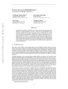
State Models For Internetworking Technologies S P Maj1, G Murphy2, G Kohli3 Abstract - New, diagrammatic state models of a switch and router were designed. The router state model can be used for all the main Interior Gateway Protocols – distance vector (RIP, IGRP), link state (OSPF) and balanced hybrid. (EIGRP). Preliminary work indicates that it also supports an Exterior Gateway Protocol (BGP). The switch state model can be used for both basic and advanced switch operation (STP, VTP and VLANs). Both router and switch models employ modularity hence both these models provide a basic model whose functionality can be enhanced by the inclusion of additional state tables. Furthermore these models are diagrammatic, self-documenting and easy to use. They employ leveling and hence provide hierarchical top down decomposition thereby controlling technical detail. These models were used as the pedagogical foundation of network curriculum and the results evaluated. It was found that these models very significantly improved student learning. Index Terms – Modeling, Routers, Switches, State Machine. INTRODUCTION There are wide ranges of equally valid approaches to teaching networking. According to Kurose [1], ‘Among the approaches towards networking curricula, one finds the more quantitative (electrical engineering) style of teaching networking versus a more software/algorithmic (computer science) approach, the more “hands-on” laboratory based approach versus the more traditional in-class lecture based approach; the bottom-up approach towards the subject matter versus a top-down approach.’ Based on a market analysis of employer expectations this university elected to implement a vendorbased, “hands-on” approach to curriculum [2]. It should be noted that vendor-based education has both strengths and weaknesses; critics and advocates [3]. Accordingly the Cisco Network Academy Program (CNAP) was introduced. The CNAP provides not only vendor specific curriculum and certification (Cisco Certified Networking Associate (CCNA) and Cisco Certified Networking Professional (CCNP)) but also low cost equipment (hubs, switches, and routers). The CNAP is based upon an educational web site that cost US$25 million to develop and an extensive repertoire of Cisco sponsored textbooks. Two main problems were found with the CNAP curriculum. Firstly, this curriculum primarily teaches
internetworking device (routers and switches) functionality using the command line interface (CLI) in conjunction with various software diagnostic tools such as the Cisco Discovery Protocol, PING, TRACE, IP ROUTE and also Telnet. The CLI allows the user to determine and modify the status of the various components of a router such as routing table entries, Address Resolution Protocol (ARP) table entries, interface status etc. However, the hierarchical CLI commands may require considerable technical expertise. Furthermore the status information of the many different device tables, interfaces etc must typically be obtained by a number of different CLI commands. This may be problematic during the teaching process when it is necessary to integrate all of this information from a number of different CLI commands. It should be noted however that for experienced network engineers the CLI is a very powerful and useful tool. Secondly, it was found that the CNAP on-line curriculum did not provide a coherent, diagrammatic, conceptual model of internetworking devices. Hence a large selection of Cisco sponsored textbooks and also non-Cisco textbooks were analyzed. It was found that internetworking devices are considered as ‘black boxes’ by introductory Cisco endorsed textbooks [4], [5], [6], [7] and introductory non Cisco endorsed textbooks [8], [9], [10], [11], [12]. The search was extended to Cisco endorsed switching books [13], [14], [15], [16] and nonCisco endorsed switching books [17], [18]; Cisco endorsed textbooks on routing [19], [20], [21] and non Cisco books on Routing [22], [23], [24], [25]; remote access books [26], [27]l and finally both general [28], [29] and specialized books on networking [30] - all with the same result. It should be noted that Cisco use finite states to explain neighbor acquisition in BGP, route acquisition in EIGRP and also neighbor and route acquisition in OSPF. However this is not integrated with router management at the CLI interface. There exist a number of network tools used for the management of large populations of devices. Such tools consolidate and automate common management tasks such as software distribution, change and audit, authorization, device inventory etc. Certainly the software management tools analyzed offered a comprehensive, modular approach to network management but do not provide an integrated, diagrammatic model of devices. There exist a number of different modeling methods that have been used to teach networking that include: OPNET [31], CLICK [20], NsClick [32] etc. However none of those
1
S P Maj, A/Prof School of Computer and Information Science,
[email protected] G.Murphy Lecturer Networking,
[email protected] 3 G.kohli, Lecturer Networking,
[email protected] 2
0-7803-8552-7/04/$20.00 © 2004 IEEE October 20 – 23, 2004, Savannah, GA 34th ASEE/IEEE Frontiers in Education Conference F2G-10
Session F2G investigated integrates internetwork device status into a single hierarchical model. Arguably what is needed is a simple, diagrammatic model that controls the technical complexity associated with the CLI and can be used as the pedagogical foundation of network technology curriculum. To assist in the development of such a model education theory was analyzed. EDUCATIONAL THEORY According to Constructivism, the dominant educational theory, students construct knowledge rather than merely receive and store knowledge transmitted by the teacher [33]. Von Glasersfeld states, “… knowledge cannot simply be transferred by means of words. Verbally explaining a problem does not lead to understanding, unless the concepts the listener has associated with the linguistic components of the explanation are compatible with those the explainer has in mind. Hence it is essential that the teacher have an adequate model of the conceptual network within which the student assimilates what he or she is being told. Without such a model as a basis, teaching is likely to remain a hit-or-miss affair.” [34]. A conceptual model of a router and a switch should therefore allow the student to assimilate concepts. For such a model to be the pedagogical basis of networking curriculum it must also be valid for different levels of complexity thereby supporting not only introductory but also more advanced concepts. Different modeling methods were used to describe internetworking device operation and evaluated for their potential effectiveness as teaching tools. MODELING METHODS
The techniques evaluated included: object-oriented modeling [36], function-oriented modeling i.e. Data Flow Diagrams [37], Process Specification [38], Jackson System Development [39, 40], Specification and Description Language [41], Structured Analysis and Design [42] and Design Approach for Real-Time Systems [43]. Most of these methods could capture information flow, and device behavior but it was difficult to relate the model results to the data extracted from the CLI. A state-oriented approach was also attempted. According to Peters [44], ‘In a state-oriented approach to specifying the behavior of software, an entity is modeled as a state machine. The behavior of an entity is described in terms of the passage of the entity through different states. The state of a software system is defined in terms of the value of the available information about the system at a particular instant in time.’ Furthermore, ‘State-oriented specifications include variables that change each time a state change occurs.’ The standard approach to this type of specification is the finite-state machine. A finite-state machine can be defined mathematically and also employs a graphical notation. The FSM is one technique used for modeling communication protocols. According to Halsall [45], ‘The three most common methods for specifying a communication protocol are state transition diagrams, extended event-state tables and high-level structured programs.’ He further states, ‘Irrespective of the specification method, we model a protocol as a finite state machine or automaton. This means that the protocol – or, more accurately, the protocol entity – can be in just one a finite number of defined states at any instant. For example, it might be idle waiting for a message to send or waiting to receive and acknowledgment.’ A communication protocol can therefore be modeled as a protocol entity that can exist in one of a number of defined states. Internetworking devices implement a number of communication protocols. Accordingly state modeling was used as the basis of modeling internetworking devices – switches and routers.
There exist a wide range of modeling methods each with its own strengths and weakness. Modeling characteristics considered of particular importance in this application are: STATE VARIABLE MODELS – ROUTER AND SWITCH diagrammatic, ease of use, ability to control detail by means of hierarchical top down decomposition and also the integration of the status of the different components of a router. A router is an OSI layer 3 device. Accordingly it implements According to Cooling [35], there are two main types of layer 3, layer 2 and layer 1 protocols. Interface status is diagram: high level and low level. High-level diagrams are typically determined by the CLI command ‘Show interface’ on task oriented and show the overall system structure with its the Router Command Line Interface (Figure 1). This output major sub-units. Such diagrams describe the overall function may be simplified to consider only selected state information of the design and interactions between both the sub-systems from this CLI output i.e. ‘FastEthernet e0/1 is up, line and the environment. The main emphasis is ‘what does the protocol is up.’ The OSI physical layer line status, of for system do’ and the resultant design is therefore task oriented. example the Ethernet interface (E0/1), is triggered by a carrier By contrast, low-level diagrams are solution oriented and must detect signal. Hence, the Layer 1 Physical connectivity state is be able to handle considerable detail. With low-level diagrams either up or down. The line protocol on E0/1, triggered by the main emphasis, applicable to this application, is ‘how does keepalive frames, is an OSI data link layer function. The Layer the system work’. Furthermore, according to Cooling, 2 Data Link Layer connectivity state can also be considered methods must be: ‘Formal (that is, there are defined rules that either up or down. The other key Layer 2 information is the must be obeyed); Visible (no implicit information); Expressive Media Access Control (MAC) address. Key Layer 3 (easy to state what we mean); Understandable (making information is the IP address and subnet mask of E0/1. All this communication simpler) and Easy to Use (an obvious need, yet can be represented on a single router diagram (Figure 2). frequently ignored).’ Internetworking devices were modeled using a number modeling techniques and the results evaluated. 0-7803-8552-7/04/$20.00 © 2004 IEEE October 20 – 23, 2004, Savannah, GA 34th ASEE/IEEE Frontiers in Education Conference F2G-11
Session F2G D e v ic e # s h o w in te r fa c e fa s te th e r n e t 0 /1 F a s tE th e r n e t0 /1 is u p , lin e p r o to c o l is u p H a r d w a r e is F a s t E th e r n e t, a d d r e s s is 0 0 0 c .3 0 d f.8 1 c 1 (b ia 0 0 0 c .3 0 d f.8 1 c 1 ) M T U 1 5 0 0 b y te s , B W 1 0 0 0 0 0 K b it, D L Y 1 0 0 0 u s e c , r e lia b ility 2 5 5 /2 5 5 , tx lo a d 1 /2 5 5 , r x lo a d 1 /2 5 5 E n c a p s u la tio n A R P A , lo o p b a c k n o t s e t K e e p a liv e s e t (1 0 s e c ) A u to -d u p le x , A u to -s p e e d in p u t flo w -c o n tr o l is o ff, o u tp u t flo w -c o n tr o l is o ff A R P ty p e : A R P A , A R P T im e o u t 0 4 :0 0 :0 0 L a s t in p u t 2 3 :4 1 :4 3 , o u tp u t 2 3 :4 1 :3 0 , o u tp u t h a n g n e v e r L a s t c le a r in g o f " s h o w in te r fa c e " c o u n te r s n e v e r In p u t q u e u e : 0 /7 5 /0 /0 ( s iz e /m a x /d r o p s /f lu s h e s ) ; T o t a l o u t p u t d r o p s : 0 Q u e u e in g s tr a te g y : fifo O u tp u t q u e u e :0 /4 0 (s iz e /m a x ) 5 m in u te in p u t r a te 0 b its /s e c , 0 p a c k e ts /s e c 5 m in u te o u tp u t r a te 0 b its /s e c , 0 p a c k e ts /s e c 5 3 6 p a c k e ts in p u t, 7 2 5 0 1 b y te s , 0 n o b u ffe r R e c e iv e d 2 7 6 b r o a d c a s ts , 0 r u n ts , 0 g ia n ts , 0 th r o ttle s 0 in p u t e r r o r s , 0 C R C , 0 fr a m e , 0 o v e r r u n , 0 ig n o r e d 0 w a tc h d o g , 1 6 4 m u ltic a s t, 0 p a u s e in p u t 0 in p u t p a c k e ts w ith d r ib b le c o n d itio n d e te c te d 3 0 0 5 p a c k e ts o u tp u t, 2 1 2 6 7 9 b y te s , 0 u n d e rru n s 0 o u tp u t e r r o r s , 0 c o llis io n s , 2 in te r fa c e r e s e ts 0 b a b b le s , 0 la te c o llis io n , 0 d e fe r r e d 0 lo s t c a r r ie r , 0 n o c a r r ie r , 0 P A U S E o u tp u t 0 o u tp u t b u ffe r fa ilu r e s , 0 o u tp u t b u ffe r s s w a p p e d o u t
ARP State Transitions
ARP State Variables
ARP State Variables Diagrams ARP
Free
Null
State
IP address
MAC address
Free
Null
Null
ARP
Pending
State
IP address
MAC address
Pending
192.168.1.1
Null
IP, Null
ARP
FIGURE 1 CLI SHOW INTERFACE OUTPUT
Resolved
Consider the layer 3 Address Resolution Protocol (ARP).
State
IP address
MAC address
Resolved
192.168.1.1
AAA.BBB
IP, MAC
FIGURE 3 STATE TRANSITIONS, VARIABLES AND DIAGRAMS (ARP)
Router TCP/IP
OSI
Internetwork
Layer 3
Implementation
Routing table Route learnt by
Destination IP
Administrative distance
Metric value
Next-hop IP
Entry age
Interface E0 E1
ARP
Interface
IP address
SNM
State
IP address
MAC address
Free
Null
Null
E0/1
Network Access
Network Access
Layer 2: Datalink
Layer 1: Physical
Interface
Line Protocol (triggered by keep alive frames)
E0/1
Up
Interface
Line status (triggered by Carrier detect signal
E0/1
Up
MAC address
FIGURE 2 ROUTER STATE VARIABLE MODEL (RIP)
This protocol, or protocol entity, can exist in one of a three defined states – free, pending or resolved. In the free state the time-to-live entry has expired; the pending state means a request for an IP entry has been sent but no reply received and the resolved state means the physical (MAC) to logical (IP) mapping is complete. Each state has a state variable – Null, IP address and MAC address. All this information may be represented in an ARP State Variables Diagram (Figure 3). This diagram may be incorporated into a diagrammatic representation of a router (Figure 2). This information may be obtained by the CLI command ‘show arp’. Similarly the state information for the routing protocol RIP may also be represented in a single table and incorporated the same diagram (Figure 2). For the sake of clarity the diagram only represent one interface (Fast Ethernet 0/1). It is possible to modify the diagrams to include multiple Ethernet interfaces and also interfaces employing different technologies such e.g. Serial point to point using HDLC.
Similarly a state diagram has been designed for a switch (Figure 4). Using this single diagram it is possible to describe the state information and hence operation of both basic and advanced switch operation – Spanning Tree Protocol (STP), Virtual Local Area Networks (VLANs) and VLAN Trunking Protocol (VTP). As a layer 2 device no protocols are implemented in the upper layers 4 to 7. Again for the sake of clarity the diagram only represents one interface (Fast Ethernet 0/1). It is possible to modify the diagrams to include multiple Ethernet interfaces. A state diagram has also been designed for a PC. A PC implements all 7 OSI layers however particular attention was paid to the lower 3 layers which interact with internetworking devices. Hence a PC state diagram has an interface table (IP address, Subnet mask and Gateway IP and an ARP table. Using the state diagrams for the internetworking devices switch and router it is possible to capture on a single diagram the information from a number of different hierarchical CLI commands. Furthermore the diagrams can be used to represent state information that may not be explicitly provided by the CLI e.g. ARP states free, pending and resolved. The diagrams also include the OSI and TCP/IP layers. It is therefore possible to clearly see which protocols operate in which layer. Arguably these state diagrams are: visible, expressive, understandable and easy to use hence of value in supporting student learning. Accordingly the diagrams were evaluated as a teaching tool. PEDAGOGICAL EVALUATION The state models of a switch and router were used as the pedagogical foundation of two postgraduate units in network technology and the results evaluated. The results indicated a significant educational benefit [46]. It was found that, ‘Postgraduate students, whose learning was based upon the state models, demonstrated a comprehension of devices comparable to a qualified and experienced expert in this field. Furthermore these students performed significantly better than
0-7803-8552-7/04/$20.00 © 2004 IEEE October 20 – 23, 2004, Savannah, GA 34th ASEE/IEEE Frontiers in Education Conference F2G-12
Session F2G other students both within the same and a different institution. Postgraduate students are arguably more mature and are likely to have better study skills than undergraduate students. However one group of postgraduate students had completed only 24 hours of instruction in contrast to CCNP students who had successfully completed the CCNA (96 hours of instruction) and an additional semester of CCNP material (at least 96 hours of instruction).’ Further work is needed but this very positive result leads to the further development of these models.
represent it on one or more tables. These tables were incorporated into a single state diagram for each protocol i.e. level 0 state diagrams. For example, the level 0 state diagram for the routing protocol EIGRP consists of the RIP state diagram with two additional tables – the topology and neighbor tables (Figure 5). Router - EIGRP OSI Layer 3
Implementation Routing table Route learnt by
Destination IP
Administrative distance
Metric value
Next-hop IP
Entry age
Interface
E0
Topology table
Switch: Cat1
Route State
Destination
TCP/IP
OSI
Implementation
State
Application
Layer 7
No
Free
Application
Layer 6
No
Application
Layer 5
No
Transport
Layer 4
No
Internetwork Layer 3
No
IP address
MAC address
Null
Null
Interface
Layer 2: Datalink
Bridge ID
Priority MAC
E0/1
Status
VLAN1 MAC
Up
MAC Type address
VLAN
IP address
Neighbour address
Via
Handle
Hold time
SNM
Interface
Line Protocol (triggered by keep alive frames)
E0/1
Up
Interface
Line status (triggered by Carrier detect signal
E0/1
Up
Root path Status cost
MAC address
FIGURE 5 EIGRP
Dynamic
Interface Linestatus E0/1
Layer 2: Datalink
Layer 1: Physical
000c.30df.81c0 ROOT BRIDGE
Interface Line Protocol
Layer 1: Physical
AD
E0/1
32769
Network Access
FD
Neighbour table Process ID
Network Access
Successors
ARP
Up
The neighbor table lists adjacent routers and associated details. The topology table includes route entries for all destinations that the router has learned including information about successor, feasible distance etc. Similarly a single, level 0, diagram was produced for IGRP (Figure 6) and OSPF. Router - IGRP OSI Layer 3
Implementation Routing table Route learnt by
Destination IP
Administrative distance
Metric value
Next-hop IP
Entry age
Interface E0
FIGURE 4 SWITCH STATE VARIABLE MODEL
IGRP table 1 Version number
ASN
Route (D Net)
Time (Up time)
ARP
ADVANCED STATE VARIABLE MODELS
State
IP address
MAC address
Free
Null
Null
Interface
The models were further developed in two ways. Firstly they were used to describe more advanced routing protocols. Secondly, in order to control even greater technical complexity diagram leveling was used. Leveling is the process of partitioning (or structuring) a complex system into a number of independent but linked units or modules of desirable size so that the system may be more easily understood. The highest level (level 0) module is a single diagram that describes the entire system. Subsequent diagrams are expansions of this level 0 diagram and numbered accordingly. Furthermore, all the diagrams must be linked thereby allowing navigation between them. Leveling is essential for controlling complexity in a hierarchical manner i.e. Information hiding.
IGRP table 2 ASN
IP address
Update time
Hold time
Flush time
Variance
Max paths
Weights
SNM
E0/1
Layer 2: Datalink
Interface
Line Protocol (triggered by keep alive frames)
E0/1 Layer 1: Physical
MAC address
Up
Interface
Line status (triggered by Carrier detect signal
E0/1
Up
FIGURE 6 IGRP
It was also possible to design a level 0 state diagram for Hot Standby Routing Protocol (HSRP) (Figure 7).
All the main Interior Gateway Protocols – distance vector (Interior Gateway Routing Protocol - IGRP), link state (Open Shortest Path First - OSPF) and balanced hybrid (Enhanced Interior Gateway Routing Protocol - EIGRP) were analyzed to obtain the most essential routing state information and 0-7803-8552-7/04/$20.00 © 2004 IEEE October 20 – 23, 2004, Savannah, GA 34th ASEE/IEEE Frontiers in Education Conference F2G-13
Session F2G and associated port states (Blocking, Forwarding, Listening or Learning).
Router - HSRP OSI Layer 3
Implementation Routing table Route learnt by
Destination IP
Administrative distance
Metric value
Next-hop IP
Entry age
Interface E0
HSRP table Interface type No
ARP State
IP address
MAC address
Free
Null
Null
Interface
IP address
Group No
Local state
Local priority
Preempt
Active Route
Active Route Priority
Virtual gateway
SNM
All experimental work was conducted on Cisco equipment – 2620XM and 2621XM routers; Catalyst 2950 and Catalyst 3550 switches. Further work needs to be conducted on different platforms to confirm that the diagrams are platform independent and hence portable. Preliminary investigations suggest this to be the case.
E0/1
Layer 2: Datalink
Layer 1: Physical
Interface
Line Protocol (triggered by keep alive frames)
E0/1
Up
Interface
Line status (triggered by Carrier detect signal
E0/1
Up
CONCLUSIONS
MAC address
FIGURE 7 HSRP
Border Gateway Protocol (BGP) is a complex Exterior Gateway Protocol. However it was possible to design a single, level 0 state diagram for this protocol (Figure 8). Router - BGP OSI Layer 3
Implementation Routing table Route learnt by
Destination IP
Administrative distance
Metric value
Next-hop IP
Entry age
Interface E0
BGP table 1 Network
Next Hop
Metric
Pre-empt
AS Path
ARP State
IP address
MAC address
Free
Null
Null
BGP table 2 BGP No
Interface
IP address
RAS No
BGP Ver
Route (local)
BGP State
Uptime
Time
Keepalive
Local
Remote
SNM
E0/1
Layer 2: Datalink
Layer 1: Physical
Interface
Line Protocol (triggered by keep alive frames)
E0/1
Up
Interface
Line status (triggered by Carrier detect signal
E0/1
Up
MAC address
FIGURE 8 BGP
Significantly the diagrams are modular hence it is possible to employ the same basic router configuration used for the routing protocol RIP and then add state tables specific to more complex routing protocols. There are a large number of switching technologies that include: Fast switching, Autonomous switching, Optimal switching, distributed switching, Cisco Express Forwarding (CEF), Netflow switching, Tag Switching etc. Preliminary work suggests that is it possible to design a single, level 0 state diagram for two Multi-layer Switching (MLS) and Cisco Express Forwarding (CEF). For most of these protocols it was possible to further design one or more subsequent diagrams at different levels e.g. level 1, level 2 etc. Different level diagrams are connected by hyperlinks allowing the user to move up or down the different levels of complexity. By example, the level 0 switch state diagram in OSI layer 2 has three tables – Interface, Bridge and VLAN. It is possible, using a hyperlink to display the level 1 diagram that shows Bridge Protocol Data Unit (BPDU) details
New, diagrammatic state models of a switch and router were developed and successfully used as the pedagogical foundation of a practical, ‘hands-on’ curriculum in networking. It was found that they significantly improved student learning. Further more extensive evaluation is needed but the very positive results encouraged subsequent development of the models. The models are diagrammatic, self-documenting and easy to use. Using the models it is relatively easy to understand the purpose and structure of the devices. The models include implementation details, derived from CLI commands, hence it is possible to verify and validate device operation. The modular nature of these diagrammatic models allows the user to appreciate the interaction between the different protocols operating on a device. Furthermore the modularity allows one to have a basic model (e.g. a router running the RIP routing protocol) whose functionality can be enhanced by the inclusion of additional state tables. Hence the router state model can be used for all the main Interior Gateway Protocols – distance vector (RIP, IGRP), link state (OSPF) and balanced hybrid. (EIGRP). It can also model Hot Standby Routing Protocol (HSRP). Preliminary work indicates that it also supports an Exterior Gateway Protocol (BGP). The switch state model can be used for both basic and advanced switch operation (STP, VTP and VLANs). Both models employ leveling and hence provide hierarchical top down decomposition thereby controlling technical detail. In effect, the diagrams integrate leveled diagrams with protocol finite state machines and the output of internetworking CLI command output. Preliminary results indicate that the models are platform independent and hence portable between different vendor devices. However further work is needed. REFERNCES 1.
2.
3.
4. 5.
Kurose, J., et al. ACM SIGCOMM Workshop on Computer Networking: Curriculum Designs and Educational Changes. in ACM SIGCOMM Workshop on Computer Networking. 2002. Pittsburgh, PA: ACM. Maj, S.P., et al., Computer and Network Installation, Maintenance and Management - A Proposed New Curriculum for Undergraduates and Postgraduates. The Australian Computer Journal, 1998. 30(3): p. 111-119. Maj, S.P. and J. Dharukeshwari, Vendor Based Network Engineering Education - An International Comparison. World Transactions on Engineering and Technology Education, 2003. 2: p. 313-316. Systems, C., Cisco Network Academy Program: First Year Companion Guide. 2nd ed. 2001, Indianapolis: Cisco Press. Heap, G. and L. Maynes, CCNA Practical Studies. 2002, Indianapolis: Cisco Press.
0-7803-8552-7/04/$20.00 © 2004 IEEE October 20 – 23, 2004, Savannah, GA 34th ASEE/IEEE Frontiers in Education Conference F2G-14
Session F2G 6. 7. 8. 9. 10. 11. 12. 13. 14. 15. 16. 17. 18. 19. 20. 21. 22. 23. 24. 25. 26. 27. 28. 29. 30. 31.
32.
33.
34. 35. 36. 37. 38. 39.
Odom, W., Cisco CCNA Exam #640-507 Certification Guide. 2000, Indianapolis: Cisco Press. Systems, C., Cisco Network Academy Program: Second Year Companion Guide. 2001, Indianapolis: Cisco Press. Shaughnessy, T. and T.J. Velte, Cisco, A Beginner's Guide. 2000, New York: Osbourne/McGraw-Hill. Hudson, K., K. Caudle, and K. Cannon, CCNA Guide to Cisco Networking. 2nd ed. 2000: Thomson Course Technology. Lammle, T., Cisco Certified Network Associate Study Guide. 2nd ed. 1999, San Francisco: Sybex. Velte, T.J. and A.T. Velte, Cisco, A Beginner's Guide. 2nd ed. 2001, New York: Osbourne/McGraw-Hill. McQuerry, S., Interconnecting Cisco Network Devices. 2000, Indianapolis: Cisco Press. Webb, K., Building Cisco Multilayer Swtiched Networks. 2000, Indianapolis: Cisco Press. Lewis, W., Multilayer Switching Companion Guide. 2003, Indianapolis: Cisco Press. Hucaby, D., CCNP Switching Exam Certification Guide. 2001, Indianapolis: Cisco Press. Hucaby, D. and S. McQuerry, Cisco Field Manual: Catalyst Switch Configuration. 2003, Indianapolis: Cisco Press. Lammle, T. and E. Quinn, CCNP Switching Study Guide. 2nd ed. 2001, San Francisco: Sybex. Thomas II, T.M., J.C. Bass, and J.E. Robinson III, Building Cisco Multilayer Switching Networks. 2000, New York: McGraw-Hill. Paquet, C. and D. Teare, Building Scalable Cisco Networks. 2001, Indianapolis: Cisco Press. McGregor, M., Semester Five Companion Guide, Advanced Routing. 2001, Indianapolis: Cisco Press. Benjamin, H., CCNP Practical Studies: Routing. 2002, Indianapolis: Cisco Press. Lammle, T., C. Timm, and S. Odom, CCNP/CCIP BSCI Study Guide. 2002, San Francisco: Sybex. Zinin, A., Cisco IP Routing. 2002, Boston: Addison Wesley. Grice, M., CCNP Guide to Advanced Cisco Routing. 2001: Thomson Learning. Thomas II, T.M., et al., Building Scalable Cisco Networks. 2000, Indianapolis: Cisco Press. Paquet, C., Building Cisco Remote Access Networks. 1999, Indianapolis: Cisco Press. Thomas II, T.M. and A. Quiggle, Building Cisco Remote Access Networks. 2000, New York: McGraw-Hill. Shinder, D.L., Computer Network Essentials. 2001, Indianapolis: Cisco Press. Systems, C., Internetworking Technologies Handbook. 2001, Indianapolis: Cisco Press. Pignataro, C., R. Kazemi, and B. Dry, Cisco Multiservice Swtiching Networks. 2003, Indianapolis: Cisco Press. Davies, N., S. Ransbottom, and D. Hamilton, Teaching Networks through Modelling. ACM SIGada Letters, 1998. XVIII (5): p. 104110. Neufeld, M., A. Jain, and D. Grunwald. Nsclick: Bridging Network Simulation and Deployment. in International Workshop on Modeling Analysis and Simulation of Wireless and Mobile Systems. 2002. Atlanta, Georgia: ACM Press, New York, NY, USA. Ben-Ari, M. Constructivism in Computer Science Education. in Twenty Ninth SIGCSE Technical Symposium on Computer Science Education. 1998. Atlanta, Georgia: ACM Press. von Glasersfeld, E., Cognition, Construction of Knowledge, and Teaching. Synthese, 1989(80): p. 121-140. Cooling, J.E., Software Design for Real-Time Systems. 1991, Padstow, Cornwall: Chapman and Hall. Booch, G., Object-Oriented Analysis and Design. 2nd ed. 1978, Redwood City, CA: Benjamin/Cummings. 830-1993, I.S., Software Requirements Specification. IEEE Standards Collecton, Sofware Engineering. 1993, NJ: IEEE. Gane, C. and T. Sarson, Structured Systems Analysis: Tools and Techniques. 1979, Englewood Cliffs, NJ: Prentice-Hall. Jackson, M., Principles of Program Design. 1975, New York: Academic Press.
40. 41.
42. 43. 44.
45. 46.
Jackson, M., System Development. 1983, Englewood Cliffs, NJ: Prentice-Hall. Rockstrom, A. and R. Saracco, SDL-CCITT specification and description language. IEEE Transaction on Communications, 1982. 30 (6): p. 1310-1318. Marca, D. and C. McGowan, SADT: Structured Analysis and Design Technique. 1988, New York: McGraw-Hill. Gomaa, H., Software Design Methods for Concurrent and RealTime Systems. 1993, Reading, MA: Addisson-Wesley. Peters, J.F. and W. Pedrycz, Software Engineering - An Engineering Approach. World Series in Computer Science, ed. D. Barron and W. P. 2000, New York: John Wiley &Sons. Halsal, F., Data Communications, Computer Networks and Open Systems. 1996, Harlow, England: Addison-Wesley. Maj, S.P. and G. Kohli, (2004, June 25-28, 2004). A New State Model for Internetworks Technology. Paper presented at the Informing Science + Information Technology Education Joint Conference, Rockhampton, OLD Australia
0-7803-8552-7/04/$20.00 © 2004 IEEE October 20 – 23, 2004, Savannah, GA 34th ASEE/IEEE Frontiers in Education Conference F2G-15