Keywords: Sign language recognition, subunit, hand motion, trajectory. 1 Introduction ... This document and other contributions archived and available at: ...
Subunit Boundary Detection for Sign Language Recognition Using Spatio-temporal Modelling Junwei Han1,2, George Awad1 * , and Alistair Sutherland1 1
School of Computing, Dublin City University, Ireland School of Automation, Northwestern Polytechnical University, Xi’an, China {jhan, gawad, alistair}@computing.dcu.ie
2
Abstract. The use of subunits offers a feasible way to recognize sign language with large vocabulary. The initial step is to partition signs into elementary units. In this paper, we firstly define a subunit as one continuous hand action in time and space, which comprises a series of interrelated consecutive frames. Then, we propose a solution to detect the subunit boundary according to spatiotemporal features using a three-stage hierarchy: in the first stage, we apply hand segmentation and tracking algorithm to capture motion speeds and trajectories; in the second stage, the obtained speed and trajectory information are combined to locate subunit boundaries; finally, temporal clustering by dynamic time warping (DTW) is adopted to merge similar segments and refine the results. The presented work does not need prior knowledge of the types of signs and is robust to signer behaviour variation. Moreover, it can provide a base for highlevel sign language understanding. Experiments on many real-world signing videos show the effectiveness of the proposed work. Keywords: Sign language recognition, subunit, hand motion, trajectory.
1
Introduction
Sign language (SL) is the dominant communication medium in the deaf community. As computer techniques evolve towards the intelligent era, SL recognition (SLR) which aims at automatically transcribing signs into text or speech by means of computer, has gained growing attention over the past 15 years. Some representative work can be found in [1-3]. Despite a great deal of effort in SLR so far, most existing systems can achieve good performance only with small vocabularies or gesture datasets. Increasing vocabulary inevitably incurs many difficulties for training and recognition, such as the large size of required training set, signer variation and so on. Therefore, to reduce these problems, some researchers have proposed a subunit-based instead of whole sign-based strategy for SLR [4-8]. In contrast with traditional systems, this idea has the following advantages. First, the number of subunits is much smaller than the * The first two authors contribute equally to this work.
Proceedings of the 5th International Conference on Computer Vision Systems (ICVS 2007) Published in 2007 by Applied Computer Science Group, Bielefeld University, Germany, ISBN 978-3-00-020933-8 This document and other contributions archived and available at: http://biecoll.ub.uni-bielefeld.de
number of signs, which leads to smaller sample size for training and smaller search space for recognition. Second, subunits build a bridge between low-level hand motion and high-level semantic SL understanding. Only after subunits become available, are structural and linguistic analysis for SL possible, and the capability of SLR could be improved largely. In general, a subunit is considered to be the smallest contrastive unit in a language. In [12], Stokoe has provided the evidence that the signs can be broken down into elementary units through the study of American SL. However, there is no generally accepted conclusion yet about how to model and segment subunits in the computer vision field. Therefore, a number of researchers have put forward a variety of definitions and segmentation solutions. In [4], Liddell et al. introduced a MovementHold model. In this model, signs are sequentially parsed into subunits, called movements and holds. “Movements” are such segments during which the signer’s configuration changes. In contrast, “holds” mean the hands remain stationary for a short term. Following this model, Vogler [5] manually detected the boundaries between movements and holds. Apparently, the model is effective under the assumption that there are clear pauses between subunits. Moreover, for a task of large vocabulary SLR, manual segmentation is impossible. Successively, Yeasin et al. [6] described subunit as a uniform dynamics. The motion breakpoints are considered as the subunit boundaries, which are located by change detection algorithm. This scheme is easy to implement, but requires the salient movement pauses as well. In addition, due to the behaviour variations of different signers, its simple change detection using a unified threshold may fail to achieve the good performance. Another interesting work was published in [7], which proposed to employ a K-means clustering approach to self-organize subunits. Nevertheless, the clustering is only built on the spatial features from each frame. It ignores the temporal information, which can be more important in SL analysis. Recently, Fang et al. [8] reported extraction of subunits for SLR using Hidden Markov models (HMM). One HMM is trained for each sign. Then, each state in the HMM is associated with one subunit. This work suffers from the shortcoming that they have to predefine the number of states for the HMM. It implies each sign has the same number of subunits. Unfortunately, this hypothesis is not true in general. To reduce the limitations of the previous work, this paper attempts to detect subunits from the viewpoint of human motion characteristics. We model the subunit as a continuous hand action in time and space. It is a motion pattern that covers a sequence of consecutive frames with correlated spatio-temporal features. In terms of the modelling, we then integrate hand speed and trajectory to locate subunit boundaries. The contribution of our work lies in three points. First, our algorithm is effective without needing any prior knowledge like the number of subunits within one sign and the types of signs. Second, the trajectory of the hand motion is considered so that the algorithm does not rely on clear pauses any more. Finally, because of the use of an adaptive threshold in motion discontinuity detection and refinement by temporal clustering, our method is robust to noise and signer variation. The rest of the paper is organized as follows. In Section 2, we present the overview of our system. Section 3 explains in detail the different components of the proposed work. The evaluations on real-world signing videos are shown in Section 4. Finally, conclusions are drawn in Section 5.
Proceedings of the 5th International Conference on Computer Vision Systems (ICVS 2007) Published in 2007 by Applied Computer Science Group, Bielefeld University, Germany, ISBN 978-3-00-020933-8 This document and other contributions archived and available at: http://biecoll.ub.uni-bielefeld.de
2
System Overview
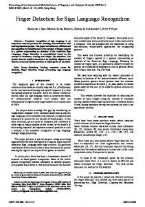
In this paper, a subunit is regarded as a motion pattern with correlated spatio-temporal features. We attempt to study the human being’s motion habit and then address the subunit boundary detection issue based on the learned information. Based on a large number of SL videos, two observations can be made. First of all, while shifting from one subunit to the next, the hand movement always goes through three phases: deceleration, acceleration, and uniform motion. This motivates us to locate the subunit boundary by discovering the speed change of hand motion. Second of all, the motion trajectory during a subunit often forms a continuous and smooth curve in 2-D or 3-D space. The trajectory generally displays considerable discontinuities surrounding the subunit boundary. The detection process is thus the recognition of perceptual discontinuities. Fig. 1 explains these two observations using an example of a real sign. Here, (a) and (b) show two sample frames respectively selected from two consecutive subunits. (c) shows the motion speed curve of two subunits, and (d) is their corresponding trajectory curve in 3-D space. As can be seen from the example, the discontinuities take place around the subunit boundary in both the motion speed and trajectory domain. Additionally, it is important to notice that the above two observations have been verified by some native speakers.
(a)
(c)
(b)
(d)
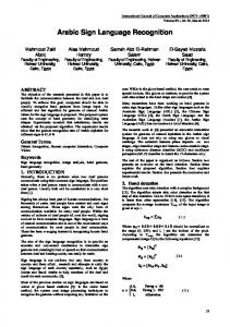
Fig. 1. An example (British sign “banana”) to explain our observations. (a): a sample frame from the first subunit; (b): a sample frame from the second subunit; (c): the corresponding motion speed curve of the left hand; (d): the corresponding motion trajectory curve in 3-D space of the left hand. As a result, this paper integrates motion speed and trajectory to segment subunits. A block diagram of the system architecture is shown in Fig. 2. The system consists of four major components. The objective of the first component is to supply speed and
Proceedings of the 5th International Conference on Computer Vision Systems (ICVS 2007) Published in 2007 by Applied Computer Science Group, Bielefeld University, Germany, ISBN 978-3-00-020933-8 This document and other contributions archived and available at: http://biecoll.ub.uni-bielefeld.de
trajectory information to the following components. They are easy to obtain once the hands can be segmented and tracked across frames. The second component, the speed discontinuity detector, works as follows. The speed difference is calculated to quantify the motion variation from frame k to frame k + 1 . Compared against a threshold T , if the speed difference is larger, a motion discontinuity between frames k to frame k + 1 is located. T is automatically decided by an adaptive thresholding technique. The third component, the trajectory discontinuity detector, is responsible for finding corner points with significant changes by measuring the sharpness of the bends in a curve. Afterwards, boundary candidates detected by both detectors serve as the input into the fourth component of the system, temporal clustering. Thanks to taking more spatio-temporal features into consideration, it can further refine the boundary detection performance.
Fig. 2. Basic architecture of our system.
3 System Components 3.1 Hand segmentation and tracking
The task of this component is to acquire motion speed and trajectory information, which is implemented by the following three steps. Firstly, given a frame k of a sign f , a hand segmentation and tracking algorithm introduced in our previous work [9, 10] is applied to get the position of the hand in this frame. Secondly, the trajectory of sign f , Tr f = [ xk , y k ]' can be obtained from hand positions. The motion speed of the hand S k is calculated based on frame k and k + 1 . Finally, both motion speed and trajectory curve are smoothed using smoothing splines [13]. It is worth noting that there are two types of hand movement in SL: dominant hand and bimanual movements, which can be distinguished from their trajectory information. In our work, for the former case, only spatio-temporal features from the dominant hand movement are used. Otherwise, features from both hands are employed. For simplicity, we illustrate the algorithm utilizing the dominant hand movement as the example in the following parts. 3.2 Motion speed discontinuity detector
This detector is done by examining local speed changes of hand movements. The speed difference by subtraction of successive frames is utilized as the discontinuity metrics. Given the hand motion speed of kth frame S k , its speed difference is defined as:
Proceedings of the 5th International Conference on Computer Vision Systems (ICVS 2007) Published in 2007 by Applied Computer Science Group, Bielefeld University, Germany, ISBN 978-3-00-020933-8 This document and other contributions archived and available at: http://biecoll.ub.uni-bielefeld.de
Dk = S k +1 − S k
(1)
Then, the obtained discontinuity values are compared with a threshold TS , and are only considerable if they exceed the threshold, that is ⎧1 SDk = ⎨ ⎩0
boundary candidate
if Dk > TS
nonboudnary candidate
else
(2)
Deciding the optimal threshold TS is a nontrivial problem. This paper employs an adaptive thresholding method invented by Otsu [14]. This technique treats the threshold optimization as a two-class data classification problem. Its principal idea is to maximize the between-class variance σ B2 and minimize the within-class variance
σ W2 simultaneously. In this paper, we determine the optimal threshold TS by minimizing the following criterion function: σ2 λ = W2 (3) σB TS = arg min λ 2 can be referred to [14]. The details of computing σ B2 and σ W
3.3 Trajectory discontinuity detector
The hand motion trajectory offers rich spatio-temporal information associated with its activity. The purpose of this subsection is to discover points of perceptual discontinuities along the trajectory curve. It is well known that corners generally correspond to such places where perceptual changes are happening. Hence, the trajectory discontinuity detector actually is transferred to a corner detector. In this paper, we apply two metrics to specify the corner points. One is the angle calculated in a neighbouring area, and the other is angle difference. If a point’s angle is very sharp or its angle is very different from angles of its neighbouring points, this point is determined as the corner. Let Tr = [ xk , yk ]' be a trajectory curve, where xk and yk denote hand’s 2-D location in kth frame. The angle ϕk associated with point ( xk , yk ) is calculated by: a 2 + b2 − c 2 ) 2ab Here, a, b, c are distances among three consecutive points. To be specific,
ϕ k = arccos(
(4)
a = ( xk , yk ) − ( xk −1, yk −1 ) b = ( xk +1, yk +1 ) − ( xk , yk ) c = ( xk +1, yk +1 ) − ( xk −1, yk −1 )
Then, the angle difference is defined as
Proceedings of the 5th International Conference on Computer Vision Systems (ICVS 2007) Published in 2007 by Applied Computer Science Group, Bielefeld University, Germany, ISBN 978-3-00-020933-8 This document and other contributions archived and available at: http://biecoll.ub.uni-bielefeld.de
(5)
Dϕ k = ϕ k +1 − ϕ k
(6)
The trajectory discontinuity detector is thus implemented by ⎧1 TDk = ⎨ ⎩0
boundary candidiate
if ϕ k < Tϕ or Dϕ k > TDϕ
nonboundary candidate
else
(7)
where two thresholds Tϕ and TDϕ are adaptively optimized using [14]. 3.4 Temporal clustering using DTW
In practice, our approach is not able to achieve an outstanding performance because of noise from the signer’s personal motion favourites (even some of them are incorrect) and motion variation from different signers. These noise and variations normally result in some false subunit boundaries and very small subunit segments. In this case, it may be necessary to introduce a temporal clustering process to remove the false boundaries and further improve the results. In our system, the points marked by both the speed and trajectory discontinuity detectors are determined to be the boundary candidates. Accordingly, the preliminary subunit segments can be produced. The principal idea of our temporal clustering is to merge consecutive similar preliminary subunit segments using additional spatiotemporal visual features. The key problem is how to measure the similarity between preliminary subunit segments. This paper applies DTW to address the problem since it has been acknowledged to be the best tool for comparing temporal signals with different length, which was indicated by [8]. DTW tries to use dynamic programming to find the best warping path that leads to the minimal warping cost between two preliminary subunits. More specifically, PS u = {ps1u , ps u2 ,...., ps um }
suppose we have two preliminary subunits PS
q
= {ps1q , ps q2 ,...., ps qn } .
from every frame.
Here,
ps ui
ps qj
and
and
represent feature vectors extracted
The warping path between PS u and PS q is denoted by:
W = {w1, w2 ,..., wk ,..., wK }
max (m,n) ≤ K ≤ m + n − 1
(8) with wk = (ik , jk ) Each element wk = (ik , jk ) is associated with a distance between the two vectors ps ui and ps qj , which is k
k
d ( wk ) = d (ps ui , ps qj ) = ps ui − ps qj k
k
k
(9)
k
The warping cost of W is given by K
K
k =1
k =1
WC ( W; PS u , PS q ) = ∑ d ( wk ) = ∑ ps ui − ps qj k
k
(10)
The warping path is subject to some constraints such as endpoint, continuity, and monotony criterions. From many satisfiable warping paths, we pick the best one with
Proceedings of the 5th International Conference on Computer Vision Systems (ICVS 2007) Published in 2007 by Applied Computer Science Group, Bielefeld University, Germany, ISBN 978-3-00-020933-8 This document and other contributions archived and available at: http://biecoll.ub.uni-bielefeld.de
the minimal warping cost, and then define the distance between two preliminary subunits PS u and PS q as K
DTW ( PS u , PS q ) = min{WC ( W; PS u , PS q )} = min{ ∑ ps ui − ps qj } k =1
k
k
(11)
The searching of best warping path can be implemented by dynamic programming. In order to make DTW work efficiently, the construction of feature vector ps k for kth frame plays an important role. In our discontinuity detectors, we only consider the local spatio-temporal features computed from consecutive frames. Here, we design our feature vector ps k by taking into account some global spatio-temporal factors. These global features are based on subunit trajectory information and are invariant to trajectory translation and scaling so that they are capable of dealing with the motion noise and variations. Assume the hand segmentation and tracking system can provide us with the following information: (1) hand location in kth frame, ( xk , yk ) ; (2) the corresponding preliminary subunit trajectory of kth frame, Tr ; (3) the centroid of Tr , ( xc , yc ) ; (4) the head position ( xh , yh ) . The feature vector ps k contains 6 factors, which are formulated as • Hand motion speed. It is calculated as: S k = ( xk +1, yk +1 ) − ( xk , yk ) •
• •
•
Hand motion direction code. First, the hand motion direction is described by: −y y θ = arctan( k +1 k ) . Then, θ is quantized into 18 direction codes of xk +1 − xk
range 20 degree each. The yielded direction code is represented by MDCk . Distance between hand position and trajectory centroid. It is calculated as: DHCk = ( xk , yk ) − ( xc , yc ) Orientation angle of vector from hand location to trajectory centroid. It is y − yk calculated as: OHTk = arctan( c ) xc − xk Distance between hand and head. It is calculated as: DHH k = ( xh , yh ) − ( xk , yk )
•
Orientation angle of vector from hand to head. It is calculated as: y − yk ) OHH k = arctan( h xh − x k In these descriptors above, the first two descriptors indicate the hand motion velocity information, the middle two descriptors measure the hand position relative to whole trajectory, and the latter two descriptors depict the hand position relative to head. To compute easily, these six spatio-temporal features are normalized into the range between 0 and 1. Finally, the feature vector is derived as ps k = ( N ( S k ), N ( MDCk ), N ( DHCk ), N (OHTk ), N ( DHH k ), N (OHH k ))
(12)
where N (•) is a normalization operator.
Proceedings of the 5th International Conference on Computer Vision Systems (ICVS 2007) Published in 2007 by Applied Computer Science Group, Bielefeld University, Germany, ISBN 978-3-00-020933-8 This document and other contributions archived and available at: http://biecoll.ub.uni-bielefeld.de
Once the similarity between preliminary subunits can be measured, the last step is to cluster these temporal segments. If consecutive preliminary subunits belong to the same cluster, we merge them into one subunit and then refine the boundary points. Due to its outstanding performance, our clustering is performed using agglomerative clustering algorithm.
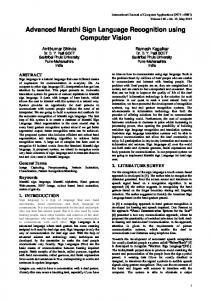
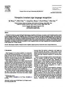
4 Experimental Results We tested the proposed work with a number of real-world signing videos. They were collected from three different sources: the ECHO * database, self-captured sequences, and data shared from other groups. Our test videos were captured by various signers in different environments. Its vocabulary comprised over 200 signs. We implemented our algorithm and ran it on a PC with Pentium 4 2.8 GHz CPU. Two subjects who are researchers of SLR were invited to manually evaluate the boundary detection results. After more than 10 hours’ subjective test, a conclusion that the performance of the proposed algorithm is promising was eventually drawn. Fig. 3 shows one sample result. The boundary frames were indicated by displaying them using grey colour. The other experiment was constructed to quantitatively evaluate our work. We randomly selected 10 signs from our dataset. To test the capability of our algorithm in handling noise and motion variations, every sign was performed with 10 repetitions. 5 examples of each sign were utilized to construct the ground truth, and the other 5 examples were used for testing. The ground truth was built through subjects’ manual segmentation. Two following metrics, recall and precision, were adopted to measure the performance. Recall = N c / N g (13) Precision = N c / N d where N g : the number of the actual subunit boundaries in ground truth N d : the number of boundaries detected by the algorithm N c : the number of actual boundaries detected by the algorithm Table 1 lists statistical detection performance. As can be seen our algorithm reaches an average recall of around 0.82 and average precision of around 0.76. Through carefully studying experimental results, especially failed cases, we found three factors mainly influence the detection accuracy. The first one is the noise and varying motions. Our test data has a large amount of noise and variations because of repeating every sign. More importantly, our videos were done by a variety of signers. The second factor is the information quality provided by the hand segmentation and tracking system. In many cases, the segmentation and tracking system cannot guarantee to get the accurate hand position and motion trajectory due to motion blur, illumination change, complicated background, and occlusion. In [8], Fang et al. used data glove to overcome this limitation. However, our work allows for any kind of signing videos. In reality, most videos in our database are with complicated * ECHO is a European Sign Language database.
Proceedings of the 5th International Conference on Computer Vision Systems (ICVS 2007) Published in 2007 by Applied Computer Science Group, Bielefeld University, Germany, ISBN 978-3-00-020933-8 This document and other contributions archived and available at: http://biecoll.ub.uni-bielefeld.de
background and need no gloves. The third factor is the hand motion complexity. We inspected failed cases in the experiment. One failure reason might be they are involved in somewhat complex movements, sometimes, bimanual movements. In our test data, many signs are bimanual movements. In summary, considering the point that our experiment did not avoid these three factors, we may claim that the performance of our work is impressive.
Fig. 3. A sample result employing the proposed algorithm. Here, no. 5, no. 13, and no. 23 frames (counted from left to right and from top to bottom) are detected as subunit boundaries. Table 1. Statistical detection performance of the proposed work. Sign number
Ng
Nd
1 2 3 4 5 6 7 8 9 10
2 2 3 2 2 3 3 1 2 2
3 2 4 2 2 2 2 1 3 2
Nc
Recall
Precision
2 2 3 2 2 1 1 1 2 1
1 1 1 1 1 0.33 0.33 1 1 0.5
0.66 1 0.75 1 1 0.5 0.5 1 0.66 0.5
5 Conclusions Nowadays, as computer technology is advancing towards a human-centric system, the new concept of learning from human behaviour to facilitate the improvement of computer intelligence attracts increasing interests. In this paper, instead of only analyzing SL linguistics, we also have studied the human action characteristics and taken advantage of them to develop a subunit boundary detection model. Motion trajectory and speed information derived from hand motion are integrated to generate
Proceedings of the 5th International Conference on Computer Vision Systems (ICVS 2007) Published in 2007 by Applied Computer Science Group, Bielefeld University, Germany, ISBN 978-3-00-020933-8 This document and other contributions archived and available at: http://biecoll.ub.uni-bielefeld.de
potential boundaries. A temporal clustering utilizing more spatio-temporal features is then applied to refine the performance. The presented model is independent of various signers. It is very easy to implement and may be efficiently incorporated in a gesture/SL recognition system. Comprehensive evaluations based on a large-scale real-world data have demonstrated the effectiveness and robustness of the proposed work. Acknowledgment. We thank Dr. Richard Bowden with University of Surrey for sharing his sign language videos. This research was partially supported by the EU Marie Curie Incoming International Fellowship, project 509477.
References 1 Charayaphan, C., and Marble, A.: Image Processing System for Interpreting Motion in American Sign Language. Journal of Biomedical Engineering 14 (1992) 419-425. 2 Starner, T., Weaver, J., Pentland, A.: Real-Time American Sign Language Recognition Using Desk and Wearable Computer Based Video. IEEE Trans. on Pattern Anal. and Machine Intell. 20 (1998) 1371-1375. 3 Liang, R.-H, and Ouhyoung, M.: A Real-time Continuous Gesture Recognition System for Sign Language. Proc. of the Third Int’l Conf. On Automatic Face and Gesture Recognition (1998) 558-565. 4 Liddell, S., and Johnson, R.: American Sign Language: The phonological base. Sign Language Studies 64 (1989) 195-277. 5 Vogler, C., and Metaxas, D.: Toward Scalability in ASL Recognition: Breaking down Signs into Phonemes. Proc. of Int’l Gesture Workshop (1999) 211-224. 6 Yeasin, M., and Chaudhuri, S.: Visual Understanding of Dynamic Hand Gestures. Pattern Recognition 33 (2000) 1805-1817. 7 Bauer, B., and Kraiss, K.: Towards an Automatic Sign Language Recognition System Using Subunits. Proc. of Int’l Gesture Workshop (2001) 64-75. 8 Fang, G., Gao, X., Gao, W.: A Novel Approach to Automatically Extracting Basic Units from Chinese Sign Language. Proc. of Int’l Conf. on Pattern Recognition (2004) 454-457. 9 Han, J., Awad, G., Sutherland, A., Wu, H.: Automatic Skin Segmentation for Gesture Recognition Combining Region and Support Vector Machine Active Learning,” Proc. of the Int’l Conf. On Automatic Face and Gesture Recognition (2006) 237-242. 10 Awad, G., Han, J., and Sutherland, A.: A Unified System for Segmentation and Tracking of Face and Hands in Sign Language Recognition. Proc. of Int’l Conf. on Pattern Recognition (2006) 239-242. 11 Yang, M., Ahuja, N., and Tabb M.: Extracting of 2D Trajectories and its Application to Hand Gesture Recognition. IEEE Trans. On Pattern Anal. and Machine Intell. (2002) 10611074. 12 Stokoe, W.: Sign Language Structure: An Outline of the Visual Communication System of the American Deaf, Studies in Linguistics: Occasional papers 8, Linstok Press, MD, 1960, revised 1978. 13 Lee, C., and Xu, Y.: Trajectory Fitting with Smoothing Splines Using Velocity Information. Proc. of IEEE Conf. on Robotics and Automation (2000) 2796-2801. 14 Otsu, N.: A Thresholding Selection Method from Gray-level Histogram. IEEE Trans. on System Man Cybernet 9 (1979) 62-66.
Proceedings of the 5th International Conference on Computer Vision Systems (ICVS 2007) Published in 2007 by Applied Computer Science Group, Bielefeld University, Germany, ISBN 978-3-00-020933-8 This document and other contributions archived and available at: http://biecoll.ub.uni-bielefeld.de