data throughout the system. In many applications the performance penalty of system-wide recovery cannot be tolerated so it is desirable for modules to include ...
Proceedings of the International Symposium on Circuits and Systems Portland, Oregon, pp. 388-393, May 1989.
SUPPORT FOR FAULT TOLERANCE IN VLSI PROCESSORS † Marc Tremblay and Yuval Tamir Computer Science Department University of California, Los Angeles, California 90024 U.S.A. ABSTRACT Fault tolerance techniques are used to allow computer systems to continue correct operation despite component failure. Hardware-supported concurrent error-detection and limited fault tolerance in system components, as implemented by coding or replication, are often required. Detection latency can be reduced by increasing the visibility of internal module state using compressed ‘‘signatures’’ of internal values. Thus, encoders, decoders, comparators, and data compression circuitry are of critical importance in fault-tolerant VLSI systems. In this paper we describe alternative implementations of such circuits and various ways in which they can be connected in VLSI modules. We also describe possible performance enhancements through the use of a technique, called micro rollback, which allows error detection to be performed in parallel with inter-module communication. As a concrete example, we present area and performance measurements of alternative microarchitectures and circuits that can be used to add detection and correction to a VLSI RISC processor we are implementing. I. Introduction Using fault tolerance techniques the reliability of computer systems can be increased beyond the reliability of the underlying hardware components. Errors generated by faulty components are detected and recovery procedures correct the errors. High-speed error-detection circuitry is needed to detect errors as soon as they occur and prevent the spread of erroneous data throughout the system. In many applications the performance penalty of system-wide recovery cannot be tolerated so it is desirable for modules to include mechanisms for rapid correction of most internal errors (i.e., local recovery). Possible errors in VLSI chips include: corruption of the contents of storage elements, incorrect results produced by computation modules (e.g., an ALU), and corruption of data and control signals (e.g., buses). These errors are the result of transient or permanent faults due to design and fabrication flaws (e.g., marginal timing, incorrect dosage of ion implants), environmental factors (e.g., noise, radiation), and wear-out mechanisms (e.g., electromigration) [3]. Many of the techniques used to detect and correct errors caused by hardware faults rely on a few basic components: encoders, decoders, comparators, and data compression circuitry. In a VLSI processor, coding can provide error detection and correction of data in the register file and other ������������������� † This research is supported by Hughes Aircraft Company and the State of California MICRO program.
storage (e.g. PSW, caches, TLB). For example, single-bit parity detects odd errors in registers, while Error Correcting Codes (ECC), such as Hamming code, provide error correction capabilities [6]. Check bits must be computed every time storage is modified, and verified whenever storage is accessed. In many modern processors a modification or access of the register file can occur every cycle, thus requiring low latency and high throughput for the circuits generating and verifying check bits. To achieve higher coverage and to detect errors in other modules (not just storage), duplication and comparison can be used [8] at either the module or chip level. To minimize detection latency, the values of internal nodes of modules should be compared each cycle. This can be accomplished without adding numerous extra pins, by ‘‘compressing’’ the values of the nodes into signatures which are then compared [5]. Since the comparison is done every cycle, compression and comparison must also be performed with low latency and high throughput. The modules needed to implement the error detection and correction techniques described above, namely encoders, decoders, comparators, and data compression circuits, are often based on Exclusive OR (XOR) gates. Alternative implementations of multi-input XOR gates are presented in in Section 2. The different implementations are evaluated with respect to performance, area, and noise margins. The evaluation is performed in the context of the microarchitecture of a VLSI RISC processor where such modules might be used for error detection and correction. In Section 3 we describe and evaluate circuits for implementing Error Correcting Codes (ECC) based on Hamming Code, in which code generation and error correction require multiple parity circuits. Through proper choice of high-speed parity circuits and the specific code to be used (M-code [6]), fast correction and check bit generation are achieved. In Section 4 we discuss the comparators and data compression circuitry needed for implementing duplication and comparison. When the two modules whose outputs are being compared are on different chips, compressing the data and sending it off chip for comparison may introduce significant delays in system operation. This potential performance penalty can be greatly reduced using a technique, called micro rollback [9], that allows detection to be performed in parallel with normal system operation. We show that micro rollback can be used to support local recovery without the need for ECC circuitry.
-2-
II. Implementation of Multi-Input XOR Gates As mentioned earlier, multi-input XOR gates are key building blocks for many error detection and correction techniques. For example, single bit parity, which is often used for detecting errors in data words, is generated and verified by XORing all bits in a data word. Similarly, the check bits in error detection and correction codes based on Hamming codes are generated and verified by computing the parity (XOR) of a subset of the bits in the word [6]. In this section we describe and evaluate several different implementations of multi-input XOR gates. Our implementation technology is double-metal 2 µ CMOS (MOSIS SCMOS design rules with λ = 1 µ). The evaluation criteria are speed, size, and noise margins. We show that the most appropriate XOR implementation cannot be selected without considering the specific use of the circuit: where on the chip it is connected, pitch matching with other circuits, use for single bit parity or for multiple check bits in an error-correcting code, etc. As a specific example, we discuss the use of the multi-input XOR gates in error detection and correction circuitry that will be utilized in a fault-tolerant VLSI RISC processor being designed at UCLA. 5V x1 x1
x2
x0 x1
x2 x3
x4 x5
x8 x9
x 10x 11 x 12x 13 x 14x 15
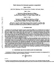
parity Figure 3: Compact Layout of a 16-input Tree of XORs is wasted. However, the layout of a binary tree can be compressed to only two rows of M /2 cells by slightly modifying the design of the basic cell, and by reorganizing the layout as shown in Figure 3. �
�
If the XOR gate is to be used for generating and checking the parity for data being transmitted over a bus, the ‘‘pitch’’ of the circuit must match the pitch of the bus. Our processor has a two-port register file with a pitch of 39 λ. The basic 2-input static XOR gate was laid out to match this pitch of 78 λ for every two bits. Given the fixed pitch, the only flexibility is with respect to the size of the cell in the direction of the bus. For the static XOR cell, this size, henceforth called stride, is 25 λ. For the complete tree, the stride is twice the stride of the basic cell plus some routing, which adds up to 70λ. A 32-bit parity is generated in 5ns. d0 = 1
x2 x 1 xor x 2
x6 x7
d1 = 0
d2 = 1
d 31 = 1
Vdd
even odd
x1 x1
x2 x2
Figure 4 : Chain of Switching Cells
di �
Figure 1: Static XOR x0 x1
x2 x3
x4 x5
x6 x7
x8 x9
di
I0
O0
I1
O1
x 10x 11 x 12x 13 x 14x 15
Figure 5: Switching Cell B. Dynamic Pass Gate Chains parity Figure 2: 16-input Tree of XORs
A. Static Implementation �
An M-input XOR gate can be implemented as a log2 M level tree of 2-input XOR gates (see Figure 2). A �
�
possible implementation of the 2-input XOR gates, using static logic, is presented in Figure 1. In a VLSI layout nonrectangular modules are undesirable since it is often impossible to ‘‘pack’’ them efficiently on the chip and significant chip area
An M-input XOR gate can be created using a chain of M switching cells [7] as shown in Figure 4. The switching cell (Figure 5) consists of four pass gates that have the capability to either interchange the inputs so that O 0 = I 1 and O 1 = I 0, if Di = 1 or to leave them intact if Di = 0. The inputs I 0 and I 1 of the leftmost cell are connected to Vdd and GND respectively. For a data word of M bits, with Z ones, the logic one signal entering the first cell will be interchanged Z times and will pass through the cells M-Z times. If Z is even then the outputs of the right-most cell will be O 0 = 1, O 1 = 0, if Z is odd, the outputs will be O 0 = 0, O 1 = 1. Alternative implementations of multi-input XOR gates using pass gate chains are investigated in the rest of this section.
-3-
N-Chain ������ . The simplest implementation of a switching cell uses four N-transistors (Figure 6). Four such cells connected serially produce a result (the parity of four bits) with a delay of 1.5ns. The delay of this circuit grows quadratically with the number of cells [7]. Hence, to compute the parity of a 32-bit word, buffers are inserted in the chain after every four cells to obtain a total delay of 10ns. The basic switching cell has a stride of 27λ. The pitch of the switching cell is 32λ in order to leave 28λ for the buffer for � �each four cells. Since an inverter is needed to provide Di and Di for each cell, the stride of the circuit is 48λ (18λ for the inverters, 3lamba for interconnections). Our simulations indicate that if the chain is implemented in an N-well process, the logic 1 levels at the internal nodes of the chain are degraded from Vdd to 3.6 volts because a logic 1 is passed through N-transistors. The following three methods improve the noise margins of the internal nodes at the expense of a small increase in area (stride). �� Di Di
Figure 6: Switching Cell Implemented with N-transistors ����������������� N-Precharged Chain. It is possible to avoid passing a logic one through N-transistors by precharging the entire chain to one and discharging nodes through the N-transistors. (Figure 7). In order to minimize the size of the cell, precharging is done through N-transistors. The voltage of the precharge signal has to be at least equal to Vdd + Vth , so that the nodes are charged to a proper logic one voltage level. A precharge signal of up to 7 volts may be needed. To eliminate the need for a second power supply, ‘‘bootstrapping’’ can be used to generate this signal from a nominal voltage Vdd [4]. Bootstrapping requires a ‘‘bootstrap’’ capacitance that is several times larger than the capacitance of the nodes that are to be charged to the high voltage. For this circuit, the precharge signal is applied to the gates of 64 transistors so the boot capacitor must be more than 100 times larger than the minimum size transistor. The noise margins are restored to normal levels and the delay for computing a 32-bit parity is 11ns (with buffers in the chain). The stride of the circuit increases by 29% for larger basic cells and for routing a precharge signal to all the cells (the size of the bootstrap circuitry is not included). �� Di Di precharge
5V
Figure 7 : N-precharged XOR Cell
P-Precharged ���������������� Chain. The requirement for a high precharge signal can be eliminated by precharging the chain through P-Transistors (Figure 8). In the layout each pair of adjacent cells share a precharge signal and well. Because of the presence of interlaced wells in the chain, the stride of the complete chain increases by 19% over the N-precharged chain. On the other hand, the noise margins are normal and the bootstrap circuit is eliminated. The delay to compute the parity through 32 switching cells and 8 buffers remains 11ns. �� Di Di precharge
5V
Figure 8 : P-precharged XOR Cell �������� . The switching cell can be implemented Dual-chain using full transmission gates (Figure 9). The noise margins are then maintained at proper levels but the stride of the circuit is 35% larger than the P-precharged chain. The speed is degraded due to the added capacitance at each node. �� Di Di
Figure 9 : Dual-Chain XOR Cell ������������������� Using Sense Amplifiers. Davis [1] proposed an implementation of a multiple-input XOR gate using a 2-level tree of 8-input XOR gates (Figure 10). Sense amplifiers speed up the calculation of intermediate results (Figure 11), providing fast computation at the expense of area and poor noise margins. The sense amplifier cell contains significantly more logic than the switching cell, and has to be made ‘‘narrow’’ to match the pitch of the data bus, resulting in a substantial increase of the stride. Including the routing necessary for� � pitch matching and two levels of logic and an inverter for Di , Di we obtain a stride of 140λ. The sense amplifier design can be use serially in order to avoid the two level structure, but the delay becomes proportional to the size of the chain, making the delay to go through a 32-cell chain 8ns. The characteristics of the different XOR gate implementations are shown in Table 1. The circuits are designed to match the pitch of the bus of our processor. The table includes the stride of each basic cell and of the complete circuits, the circuit delay, and the noise margins.
-4-
8 inputs
8 inputs
8 inputs
� � �������� ������������������������������������������������������������������� ��������������������������� � � � �������� ��������������������������Data ���� ���� ���� ��Bits ���� ���� ���� ���� ���� ���� ���� ���� ���� ���� ���� ���� ���� ���� ���� ��� �� ���� ���� ��Check ���� ���� ���� ���� ���� ��Bits ���� ���� ���� ���� � � ����������������������������������� �� �� �� � � � � 1111111111222222222233 3 3 3 3 3 3 3� � � � � � ���i����� ��01234567890123456789012345678901 ����������������������������������������������������������������� ��2����3����4����5����6����7����8� � � C � 11111111111111 � 1 � 0 � � � � C 1 11111 111111111 1 � � � � 1111 1111 11111 1 � C2 � 1 � � � C3 � 1 � 1 111 1 11 111 111 � 1 � C � � 1 1 1 1 1 1 111 1111 1 � 1 4 � � � � C5 � 1 1 1 11 1 111 1 1 1 11 � 1 � �� � � �
8 inputs
= Switching Cell = Sense Amp.
Parity
Figure 10: Tree of 8-input XOR with Sense-Amp. ���
latch
trigger D1 D1
D2D2
� �C ����6������������1��������1������1����1��������1������1����1������1����1����111 ��������������������������������1�
D 32D 32
Table 2: M-Code Parity Check Matrix for 32-bit Words Data Bits d0 d1 d2 d3 d4
d 30d 31
Check Bits c0 c1 c2 c3 c4 c5 c6
����
output output M-code Generation
Figure 11: Chain of XORs with Sense Amplifier � � ����������������������������������������������������������������������������������������������������� �
�
� � ��������������������Implementation 32-bit ���� ���� ���� ���� ���� ���� ���� ��� �� ���� ���� ���� ���� ���� ��of ���� ��� a�� ���� �� ���� ���� ���� ���� ��XOR ��� �� ���� ���� ���� ��Gate ���� ���� ���� ��� �� ���� ���� ���� ���� ���� ���� ���� ���� � ���������������������� �� �� �� �� � Cell Noise � � Circuit � � � Implementation � Delay � � � � � ����������������������������������������Stride ����������������Stride ��������������������������������Margins ������������� � � � � � � Static tree � ������������������������������������� ������25 ����λ ������� ������70 ������λ����� ��������5ns ��������� ����normal ������������� � � � � � � Chain + buffers � � N-chain 27 λ � 48 λ � 10ns � poor � � � � � � N-precharged* � 35 λ � 62 λ � 11ns � normal � P-precharged 43 λ � 70 λ � 11ns � normal � � Dual-chain 63 λ 84 λ � 16ns � normal � � � � ����������������������������������������������������������������������������������������������������� � � � � � � Chain + Sense-A. � � � � � 2-level 40 λ � 140 λ � 4.5ns � poor � � � � � � �� ������1-level ������������������������������������40 ����λ ������������76 ������λ������������8ns ��������������poor ����������� � ��* ����without ������������bootstrap ����������������circuitry �������������������������������������������������������������������
� �
1 or 2 Errors � � �
Decoders � � � � � �
Corrected Word � �
Figure 12: Error Detection and Correction � � ��
Table 1: Characteristics of each Implementation III. Error Correction Circuitry The XOR circuits described in the previous section can be used for error detection with a single parity bit. A simple method for correcting errors locally, without resorting to system-wide recovery, is to use error correction codes (ECC) [6]. In this section we discuss error correcting codes based on Hamming Code, which are commonly used to detect and correct errors in storage elements [6]. The check bits of these codes are generated and verified using multi-input XOR gates. Each check bit is generated by XORing a different subset of the data bits. When storage is accessed, the same subsets and their corresponding check bits are XORed to produce a syndrome which is used to correct some errors and flag others (e.g., multiple bit error) as uncorrectable [6]. This section focuses on circuits which provide single error correction and double error detection (SEC-DED). The measurements presented are based on a SEC-DED code for a
32-bit word. We use a subset of Hamming code, called Maintenance code (M-code) [6]. Both Hamming and M-code require XORing several bits to obtain the check bits but M-code has the advantage that the maximum number of bits to XOR is smaller, resulting in faster operation. For example, for a 32-bit word, check bits are generated by XORing at most 14 bits, while Hamming code as used in[1] requires XORing up to 32 bits. Table 2 represents the parity check matrix for a 32-bit word. Each row contains the bit positions to be XORed to generate each check bit. Since seven check bits are needed for a 32-bit word, seven rows of XOR gates are required. A block diagram of the circuitry is shown in Figure 12. Since seven rows of XOR gates are needed when using M-code, minimizing the stride of each multi-input XOR gate becomes more critical than when there is only one row for single-bit parity. Since the inputs to each XOR gate are not necessarily adjacent, a static implementation (Figure 3) is not appropriate — it requires excessive routing. If area is the main concern, N-chain XOR gates, without precharging, can be used. For a wide pitch (58λ), the stride of each N-chain can be reduced to 19λ and the check bits can be computed in 3.8ns. XOR gates based on P-precharged chains can be used if normal noise margins are needed. To maximize speed, XOR gates
-5-
based on N-chains with sense amplifiers can achieve a delay of 2.5ns (two level tree, two sets of seven bits in the first level). When a data word is accessed, a seven-bit syndrome is generated by XORing all the bits in each row, including the check bits. To differentiate between single-bit and double-bit errors, an XOR of the syndrome is generated [6]. If the result is one, there is a single-bit error and correction can be performed. If the result is zero, and the syndrome bits are not all zero, a double-bit error is signaled. For single-bit error correction, the erroneous bit is identified by the syndrome. Using a decoder and a controlledinverter (XOR gate), the faulty bit can be flipped (see Figure 12). Table 3 shows the areas and correspondings delays for three different implementations. � ����������������������������������������� � � ����������������������������������������� Area and Delay of ECC Circuits (pitch� = 39λ) � � � ����������������������������������������� � Circuit Area � � Delay � � ����������������������������������������� � � � generation of check bits � � � 2 � � - N-chain 262080 λ � 3.8ns � � � 2 - P-precharged 4ns � � 409344 λ � � � 2 � 394368 λ � 2.5ns � - Sense-amp. � � 2 � � 21756 λ 2ns � � identification of the error � � � � decoding + correction 259584 λ2 5ns � � � � � total � � � � � N-chain 543420 λ2 � 10.8ns � � � 2 � � - P-precharged 690684 λ 11ns � �� � � � - Sense-amp. 675708 λ2 9.5ns ����������������������������������������� Table 3: Area and Delay of ECC Circuitry (one bus) The datapath in many microprocessors is based on two parallel buses whose data bits are interleaved. Two simultaneous reads from the register file are usually supported. In order to simultaneously detect errors on both buses, the stride of the ECC circuitry has to be significantly increased. Specifically, the detection subcircuit (seven multi-input XORs and a XOR for the syndrome) must be doubled. If, once an error is detected, multiple phases are available for correction, one syndrome decoder can be shared by both buses and correction can be done sequentially. The correction circuitry must also be doubled. In our design, with a bus pitch of 39λ and XOR gates implemented as P-precharged chains, the stride of the detection circuitry is 328λ, the decoder is 147λ, and the correction is 61λ. For two buses, sharing the decoder can decrease the total stride from 1070λ to 933λ. For data in the register file, the ECC circuitry can be connected between the register file and the ALU. If it is connected ‘‘serially’’ the processor cycle time must be stretched to accommodate the added delay. Much of this performance penalty can be avoided by connecting the ECC circuitry in parallel with the datapath. The data from the register file is sent to the ALU without waiting for the result of ECC. The ECC circuitry must be fast so that if an error is detected, it is possible to abort the operation before there is permanent damage to the processor state.
IV. Duplication and Comparison Using duplication and comparison it is possible to achieve high-coverage error detection for all types of modules [8, 2]. Two identical modules process the same information in parallel and some of their output pins are compared every cycle (Figure 13). In this section we described the circuits needed for duplication and comparison. These include comparators as well as data compression circuitry necessary to reduce the pin requirements when the two modules whose outputs are compared are on different chips. We show how error correction can be performed in a system based on duplication and comparison by transferring state from the fault-free module to the faulty module. A. Compression It is often impossible or undesirable to duplicate large VLSI modules, such as processors, on the same chip. Duplication and comparison with such modules requires using at least two chips. Hence, comparison is limited to the information available at the pins. Since many of the results computed by the processor do not immediately appear at the pins, if the comparison is based only on values available at the pins, the system is likely to have long detection latencies. This problem can be solved by including internal information, such as the output of the ALU, the PSW, and various state registers in the comparison. The number of bits to compare may easily add up to one hundred, requiring many extra pins. In order to reduce the number of bits to be transmitted across pins to the comparator, the values on internal nodes can be ‘‘compressed,’’ leading to large reduction in pin bandwidth requirements with small reductions in coverage [5]. Processor 1
Processor 2
Internal
Internal
State
State
100 bits
100 bits
Compression
Compression
4 bits
4 bits
Comparator
Figure 13: Processors Running in Duplex Mode There are many possible ways to ‘‘compress’’ data [5]. In the context of this discussion, a simple and effective data compression technique is to use several parity bits computed across the data ‘‘word’’ to be compressed. For example, for a 32-bit word, we can compute a 4-bit ‘‘signature’’ by constructing four interleaved parity chains, each consisting of eight bits from the word. Each chain includes every fourth bit in the word. The implementation of this interleaved parity scheme uses the circuits already described in Section 2. Given two 32-bit errors, one correct and one erroneous, a large percentage of errors can be detected by comparing the 4-bit signatures of the two words: all single bit errors, any odd number of bit errors, and many multiple bit adjacent errors. For random multi-bit errors, 93.75% of the errors will be detected.
-6-
A 4-bit signature of a 32-bit word can be generated in 3ns using four 8-input P-precharged chains (Figure 14). The four chains can be compressed into one chain where every fourth cell is connected through metal lines. For a pitch of 39 λ we obtained a stride of 133 λ, which includes an inverter, a precharge line, and internal routing. b0 b1 b2 b3 b4 b5 b6 b7
b 28b 29b 30b 31
data
module. In order to identify which module is faulty, each module must be capable of local detection of errors in storage. This requires parity encoders and decoders on each module. However, as discussed in sections 2 and 3, the area for singlebit parity generation and verification is less than 10% of the area for ECC circuitry. Furthermore, this techniques allows recovery from many errors that cannot be handled by conventional SEC-DED codes. V. Summary
Chains of XORs
p1 p2 p3 p4 compressed word
Figure 14: Interlaced Parity used for Compression a0
5V
a1
a 31
prech.
a = b? b0
b1
b 31
Figure 15: A 32-input Comparator B. Comparison A comparator can be implemented using the design shown in Figure 15. We designed the layout of a 32-input comparator to match the pitch of the datapath and its stride is 44λ. The output of the comparison is computed in 5.8ns. C. Micro Rollback and Error Correction The necessity of off-chip transmission of data for comparison increases the error detection latency beyond the point where the processor can be interrupted and its last instruction restarted if an error is detected. Several clock phases are necessary for compressing the data, sending the result off-chip, latching the data in the comparator, comparing the inputs, sending the outcome back to the processor, and latching in the result. We have previously introduced a technique, called micro rollback, which allows VLSI modules to roll back their state to its value several clock cycles earlier [9]. With this technique, it is possible to begin processing information several cycles before its validity is verified, since if it turns out to be erroneous, its effects can be undone. In a system that supports micro rollback, duplication and comparison across chip boundaries can be supported with minimal performance penalty. In a system based on duplication and comparison with micro rollback, local recovery from most errors can be supported without conventional ECC circuitry. When the outputs of the two modules differ, the modules are rolled back several cycles. If the error was caused by a transient fault on, for example, the buses or ALU, it is unlikely to recur when the last few cycles are ‘‘repeated.’’ If the error was caused by a transient fault in storage (e.g. register file), recovery requires copying the valid state from the fault-free module to the faulty
Most fault-tolerant systems require that key components, such as VLSI processors, include significant local error detection and correction capabilities. The circuits that provide these capabilities are typically encoders, decoders, comparators, and data compressors. These circuits must provide low latency, high throughput operation in order to be able to perform checks every cycle and prevent erroneous information from propagating throughout the system. Multi-input XOR gates are critical building-blocks for many of these circuits. We have described several implementations of XOR gates: a tree of static XOR gates, a compact N-chain, two precharged chains and a dual-chain that provide normal noise margins, and a fast implementation based on sense amplifiers. The discussion included major tradeoffs (speed, area, noise margins, pitch matching) in the implementation of circuits for generating parity, for computing ECC check bits, for correcting errors, and for compressing and comparing data. We discussed a few of the interrelationships between the microarchitecture of the processor and the appropriate choice for detection and correction circuitry. We described how duplication and comparison across chip boundaries can be used for high-coverage error detection and correction with minimal performance penalty. The key features of this scheme are ‘‘compression’’ and comparison of the values on internal nodes as well as on buses and the use of a technique, called micro rollback, which allows error detection and correction to be performed in parallel with intermodule communication. References 1. 2. 3. 4. 5. 6. 7. 8. 9.
H. L. Davis, ‘‘A 70-ns Word-Wide 1-Mbit ROM With On-Chip Error-Correction Circuits,’’ IEEE Journal of Solid-State Circuits SC-20(5), pp. 958-963 (October 1985). Advanced Micro Devices, Am29000 Streamlined Instruction Processor User’s Manual, 1987. E. A. Doyle, ‘‘How Parts Fail,’’ IEEE Spectrum 18(10), pp. 3643 (October 1981). L. A. Glasser and D. W. Dobberpuhl, The Design and Analysis of VLSI Circuits, Addison-Wesley (1985). E. J. McCluskey, ‘‘Built-In Self-Test Techniques,’’ IEEE Design and Test 2(2), pp. 21-28 (April 1985). T. R. N. Rao and E. Fujiwara, Error-Control Coding for Computer Systems, Prentice Hall (1989). M. Sievers and D. A. Rennels, ‘‘An LSI Totally Self-Checking Hamming Coded Memory Interface,’’ International Symposium on Circuits and Systems, pp. 1176-1179 (May 1982). Y. Tamir and C. H. Sequin, ´ ‘‘Self-Checking VLSI Building Blocks for Fault-Tolerant Multicomputers,’’ International Conference on Computer Design, pp. 561-564 (November 1983). Y. Tamir, M. Tremblay, and D. A. Rennels, ‘‘The Implementation and Application of Micro Rollback in FaultTolerant VLSI Systems,’’ 18th Fault-Tolerant Computing Symposium, Tokyo, Japan, pp. 234-239 (June 1988).