... Francesco d'Errico, Francisco Giles Pacheco, Ruth Blasco, Jordi ... Gutiérrez López, José S. Carrión, Juan José Negro, Stewart Finlayson, Luís M. Cáceres, ...
A rock engraving made by Neanderthals in Gibraltar
Joaquín Rodríguez-Vidal, Francesco d’Errico, Francisco Giles Pacheco, Ruth Blasco, Jordi Rosell, Richard Jennings, Alain Queffelec, Geraldine Finlayson, Darren A. Fa, José María Gutiérrez López, José S. Carrión, Juan José Negro, Stewart Finlayson, Luís M. Cáceres, Marco A. Bernal, Santiago Fernández Jiménez, Clive Finlayson
Supporting Information Appendix
- Supplementary text 1
- Figures S1-S21
- Tables S1-S5
- Supplementary references
Supplementary text
Text S1. Lithic assemblage from Gorham’s Cave level IV Level IV was first excavated between 1997 and 2005, when 222 lithics were recovered. See (S1) for a detailed description of this assemblage and (S2) for a discussion of its stratigraphic context. Level IV was excavated again in 2011 and 2012, when 72 additional lithics were found.
Description of the lithic assemblage In total, 294 lithics have been recovered in Level IV to date. They include 21 cores, 155 flakes, 10 retouched flakes, 20 flake fragments, and 20 pieces of debitage (Table S2). Sixtysix nodules, two thirds of which were made of quartzite, must have been intentionally brought into the cave since they are absent in the compact dolomite composing the cave walls. Flint dominates the assemblage (42%). Of the 155 flakes, 95 are made on flint, 55 on quartzite, and 5 on radiolarite. Three types of flint featured in the assemblage: grey-green, black and red. Radiolarite chert is present in low proportion. These raw materials are common around the Rock of Gibraltar. Similar nodules of sandstone, quartzite and quartz to those used in the cave can be found in the alluvial-marine formations outcropping along the coastline and river mouth basins near the Rock. On the other hand, flint comes from different seams within the Rock. In summary, all the raw materials are autochthonous and were probably collected at fossil beaches near the caves (S3-S6). Two core types were recorded in Level IV (Table S2): Levallois (n = 3), Discoidal (n = 7). Two of the Levallois cores, made on a fine-grained quartzite and flint, are recurrent centripetal. One of these is made on a flake fragment. The centripetal technique was preferentially applied to rounded pebbles. The flakes are almost exclusively non-cortical, suggesting that primary lithic reduction did not occur at the rear of the cave. More than half have unifacial striking platforms, followed by bifacial and multifacial forms. The high number of unifacial platforms is indicative of
discoidal reduction methods, while the presence of bifacial and multifacial platforms is indicative of the Levallois method (S7, S8). There is high variability in the morphology of the striking platforms. The straight striking surfaces are the most common followed by the singleangle striking surfaces. The bulbs on the ventral surface share almost equal proportions of marked and diffused forms. The negative scars on the dorsal surface indicate the presence of pseudo-Levallois and Levallois centripetal lithic reduction both for flint and sandstone, with some flaking planes forming cutting edges that are very suitable for use. Small and medium sized flakes dominate the assemblage. The blade index (S9) is low with flint being the dominant raw material present as blades. The proportion of tools in the assemblage is low (10/294). Medium or large sized flakes were used to produce tools. Six were made on flint and four on quartzite. There are two abrupts, two notches, two denticulates, and four side-scrapers, including a transverse form and a sidetransverse scraper with worked cutting edges that come to a point. Two side-scrapers are shaped on Levallois points using simple retouch. Both are made on flint. The notches are made on the ventral side of quartzite pieces, while the denticulates exhibit simple, deep and direct retouch on the left side in one piece and on the transverse side in the other. Pacheco et al (S1) also recorded one quartzite and one limestone unifacial chopper. Raw material variability does not drive platform shape or the alteration of the dorsal surface, and these two main raw material types are fine grained and could be knapped in a similar manner.
Interpretation of the lithic assemblage A number of diagnostic features undoubtedly attribute Level IV lithics to the Mousterian: 1) preferential Levallois and discoidal lithic reduction techniques, demonstrated by the presence of ten cores, unifacial, bifacial and multifacial platforms on two thirds of the flakes, and centripetal Levallois flakes and points; 2) low laminar index and medium-small size flakes; 3) presence of typical side scrapers, denticulates and notches; 4) absence of stone tools with diagnostic Upper Palaeolithic forms such as those recovered in overlying Solutrean and
Magdalenian levels. The paucity of cores and cortical flakes indicates that primary reduction did not take place in the rear of the cave. This activity may have occurred near or at the front of the cave, or at a raw material source. The presence of un-retouched flakes and the small number of cores in the assemblage indicates that secondary reduction took place at the back of the cave to produce side scrapers, denticulates and notches. The medium-small size of the blank and retouched tools is due to the size of available raw material rather than exhaustion. Considering that the Mousterian in Iberia and elsewhere in Europe is only associated with Neanderthals, we conclude that the lithics from Gorham’s Cave level IV reflect Neanderthal use of the rear of this cavity.
Supplementary Figures
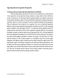
Figure S1. Tectonic and solution-etched cracks on the exposed surfaces of the fine-grained limedolostone of the Gorham’s Cave walls. These cracks have also been observed in the older surfaces of bedrock that were covered by Pleistocene sediments, and also by alteration layers. The plot shows the clear difference in width/depth ratio between the archaeological engraved lines and natural cracks. Grey dots represent superficial lines whose depth, ranging between 200µm and 700µm, could not be precisely measured. The results show that there is no statistically significant difference in the width of natural cracks and the archaeological lines but that the width of the superficial lines is significantly lower than the other two. On the other hand, there is a statistically significant difference between the depth of the natural cracks and that of the engraving, which are shallower. The depth of the superficial engraved lines is statistically significantly even shallower than either the engraving or the natural cracks: 1) natural cracks –blue dots (width): mean=4.4372 (95% CL 4.0162-4.8581); 2) natural cracks –blue dots (depth): mean = 19.7 (95% CL 17.74-21.66); 3) anthropogenic engraved lines –red dots (width): mean = 5.2717 (95% CL 4.6163-5.927); 4) anthropogenic engraved lines –red dots (depth): mean = 1.18 (95% CL 0.822-1.538); 5) superficial anthropogenic engraved lines –grey dots (width): mean = 1.6286 (95% CL 1.0847-2.1725); and 6) superficial anthropogenic engraved lines –grey dots (depth): mean = 0.236 (95% CL 0.187-0.285).
Figure S2. Mousterian tools from Level IV of Gorham’s Cave: 1) GOR’05-AA5-IV-38/ Coarse-grained quartzite; 2) GOR’05-AA5-IV-38/ Coarse-grained quartzite; 3) GOR’05-AA5-IV-46/flint; 4) GOR’05AA5-IV-46/flint; 5) GOR’05-A6-IV-95/flint; 6) GOR’07-AA5-IV-2/flint.
Figure S3. Typical Solutrean tools from Gorham’s Cave Level III: Unifacial tools (1 to 3), bifacial laurelleaf point (4), tanged points (6-8), bifacial pedunculate point (5). All are made on flint.
Figure S4. Vertical distribution of Mousterian and Solutrean lithic artifacts located 45 cm either side of the N-S profile above the engraving. The dotted line identifies the limit between levels IV and III. The engraving was covered by ~ 40 cm of sediment belonging to level IV.
Figure S5. (A) Plan of the Upper Gallery in Gorham’s Cave showing the location of the engraving. (B) Section of the cave drawn in (A) indicating the location of main archaeological levels on the exposed profiles, the reconstructed limit between level III and IV, and the location of the engraving. (C) photo showing, from the bottom to the top, the engraving (circled), the exposed bedrock, and level IV. Notice an in situ Levallois core partially exposed on level IV profile.
Figure S6. Detail of the duricrust damaged by desquamations showing three microscopic layers of alteration: a white lower layer (layer 1), a light brown intermediate layer (layer 2), and an upper black layer (layer 3).
Figure S7. X-ray Diffraction (XRD) analysis showing the mineralogical composition of white layer 1, orange-brown layer 2, and black layer 3
Figure S8. Scanning Electron Microscope (SEM) images and Energy Dispersive Spectrometry (EDS) analyses of the alteration layers: (A) Back-scattered image of the transition between the light brown layer 2 (at the top) and the duricrust layer 3 (at the bottom), (B) secondary electron image of white layer 1, and (C) secondary electron image of black layer 3.
Figure S9. Stone tools used to experimentally engrave weathered blocks of lime-dolostone. The hatched lines indicate the area of the tools which were active during the engraving process (see Table S4 for a description of the tools and actions).
Figure S10. Incisions produced experimentally when cutting a fresh pork skin on a weathered block of lime-dolostone with a flint (left) and a microquartzite (right) blade (left: experimental tool n. 6; right: experimental tool n. 7, see Table S4). Scale bar = 1 cm.
Figure S11. Experimental multiple stroke lines engraved by repeatedly passing the tool tip into the groove in the same direction (from top to bottom). Numbers indentify the tools used (see Figure S9 and Table S4). Scale bar = 1 cm.
Figure S12. Sections of the lines composing the Gorham's Cave engraving, reconstructed from the 3D model of the engraved surface.
Figure S13. Photo of the engraving with location and number of the microscopic images presented in the Supplementary figures S14-S20.
Figure S14. Close-up view of line L4 showing the morphology of the groove and internal subparallel striations hardened by the duricrust. Scale = 1 mm.
Figure S15. Close-up view of line L7 showing the morphology of the groove and, at places, the remnants of subparallel striations hardened by the duricrust as well as areas outside the groove with discontinuous duricrust. Scale = 1 mm.
Figure S16. Detail of Figure S15 revealing local scalloping of the groove bottom and area displaying well preserved striations produced by protrusions of the tool tip during its displacement into the groove. See Figure 4 for comparable features on experimental engraving. Scale = 1 mm.
Figure S17. Close-up view of line L1 showing the flat bottom of the groove and a localized damage of the duricrust exposing the underline lime-dolostone. Scale = 1 mm.
Figure S18. Detail of Figure S17 revealing well preserved striations hardened by the duricrust. See Figure 4 for comparable features on experimental engraving. Scale = 1 mm.
Figure S19. Close-up view of the crossing of lines L1 and L4 revealing the presence of a single stroke line engraved, at the end of the engraving process, in L1. Scale = 1 mm.
Figure S20. Macrophoto of lines L9-11 and crossing of L9 and L1. Notice a) the removal of the duricrust (top right) damaging L10 and L11 and demonstrating their antiquity, b) the obliteration of L9 and fringes at the end of L1 by the duricrust, c) the slenderness and similar internal morphology of L9-11 suggesting single strokes made by the same tool in rapid succession, d) change of direction of L9 when crossing L1 suggesting the tool was displaced from top left to down right. Scale = 1 cm.
Figure S21. Sketch summarising the order of the engraving lines, breaks, and formation of the duricrust. Engraved lines belonging to a new engraving episode are in grey, breaks in white. Arrows indicate the direction of the tool. Simple head arrows indicate single stroke lines, double arrows multiple stroke lines in one direction. Gray background in “e” identifies the formation of the duricrust. Scale = 5 cm.
Supplementary Tables Table S1. AMS 14C dates from level IV of Gorham’s Cave (data from Finlayson et al. 2006 ref.29 in the manuscript).
Lab. Code
Material
Conventional radiocarbon age yr BP
δ13C (‰)
Cal. age yr BP IntCal09 (2σ)
B‐196785 B‐196773 B‐238791 B‐185344 B‐185346 B‐238784 B‐196770 B‐196784 B‐196791 B‐238792 B‐184048 B‐184049 B‐238785 B‐238781 B‐196779 B‐196778 B‐238782 B‐238787 B‐196786 B‐196792 B‐196776 B‐238788 B‐184045 B‐196768 B‐196787 B‐196772 B‐196769 B‐196789 B‐196771
charcoal charcoal charcoal (H) charcoal charcoal charcoal (H) charcoal charcoal charcoal charcoal (H) charcoal charcoal charcoal (H) charcoal (H) charcoal charcoal charcoal (H) charcoal (H) charcoal charcoal charcoal charcoal (H) charcoal charcoal charcoal charcoal charcoal charcoal charcoal
26,070±180 26,400±220 26,470±220 27,020±240 27,280±220 27,930±250 28,170±240 28,360±240 28,570±240 28,800±280 29,210±190 29,240±190 29,280±280 29,320±300 29,400±270 29,720±280 29,750±330 29,760±310 29,910±300 30,310±310 30,560±360 30,630±340 31,110±230 31,290±340 31,480±370 31,780±360 31,850±380 32,100±400 32,560±390
‐25.6 ‐23.2 ‐24 ‐25 ‐ * ‐25.9 ‐26.1 ‐25.2 * ‐25.2 ‐ ‐26.3 ‐23.7 ‐25.4 ‐24.8 ‐23.6 ‐24.4 ‐24.7 ‐24.7 ‐24.5 ‐24.6 ‐23.7 ‐25.8 ‐23.7 ‐23.1 ‐23.5 ‐24.5 ‐25.1
30,440‐31,120 30,620‐31,290 30,690‐31,320 31,050‐31,620 31,140‐31,890 31,470‐32,880 31,630‐33,130 31,810‐33,340 31,930‐33,930 32,430‐34,500 33,300‐34,540 33,320‐34,550 33,230‐34,620 33,230‐34,650 33,330‐34,660 33,520‐34,890 33,460‐34,970 33,510‐34,960 33,690‐35,080 34,460‐36,180 34,570‐36,270 34,610‐36,270 35,030‐36,340 35,050‐36,510 35,090‐36,620 35,180‐36,900 35,160‐37,080 35,300‐37,710 36,460‐38,460
(*) the original sample was too small for a 13C/12C ratio measurement. However, a ratio including both natural and laboratory effects was measured during the 14C detection to derive a Conventional Radiocarbon Age, suitable for applicable calendar calibration. (H) Hearth samples.
Table S2. Lithics recovered from Gorham’s Cave Level IV.
Raw material
Nodule/NB Levallois
Discoid
Retouched flakes Coresa Flakesb Choppers Flake fragments
Debris Total
Cores Flakes
Cores Flakes
Fine‐grained quartzite
3 (5)
1 (33) 8 (29)
3 (43) 26 (33)
4 (40)c
‐
12 (26)
‐
3 (15)
1 (5)
61 (21)
Coarse‐grained quartzite
44 (67)
‐
4 (57) 4 (5)
‐
7 (64)
4 (9)
‐
6 (30)
11 (55) 81 (28)
Flint
5 (8)
1 (33) 17 (61)
‐
47 (59)
6 (60)d
2 (18)
31 (66)
‐
6 (30)
8 (40)
123 (42)
Radiolarite
‐
1 (33) 2 (7)
‐
3 (4)
‐
2 (18)
‐
‐
5 (25)
‐
13 (4)
Other raw materials**
14 (21)
‐
‐
‐
‐
‐
‐
‐
2 (100)
‐
‐
16 (5)
Total
66 (22)
3 (1)
28 (10)
7 (2)
80 (27)
10 (3)
11 (4)
47 (16)
2 (1)
20 (7)
20 (7)
294
1 (4)
Nodule/NB: Natural Base (unmodified lump of rock brought to the cave). Percentages are indicated in brackets. a
indeterminate debitage technique (e.g., exhausted core).
b
limestone, dolomite, quartz, and quartzite.
c
1 side-scraper and 3 denticulates.
d
3 side-scrapers, 1 denticulate and 2 side-scrapers shaped on Levallois points using simple retouch.
Table S3. Lithic recovered from Gorham’s Cave Level III (Solutrean).
NB NH Core Flake SP Core Flake OR Core Flake Tool type* Side‐scraper End‐scraper Denticulate scraper Notches Shouldered blade Double‐backed blade Shouldered backed point Tanged backed point Double‐ended foliate point Bifacial foliate point Double‐ended bifacial foliate point Tanged bifacial foliate point Flake fragments Debris Total
Fine‐grained quartzite 45 5 ‐ 10 ‐ 2 1 ‐ ‐ ‐ ‐ ‐ ‐ ‐ ‐ ‐ ‐ ‐ ‐ 2 2 67
Large‐grained quartzite 2 4 3 3 ‐ ‐ 1 ‐ ‐ ‐ ‐ ‐ ‐ ‐ ‐ ‐ ‐ ‐ ‐ 2 ‐ 15
Flint Radiolarite Other raw materials 2 1 9 2 ‐ 1 1 ‐ ‐ ‐ 1 1 8 ‐ ‐ 1 ‐ ‐ 1 ‐ ‐ 1 ‐ ‐ 1 ‐ ‐ 1 ‐ ‐ 2 ‐ ‐ 1 ‐ ‐ 1 ‐ ‐ 1 ‐ ‐ 1 ‐ ‐ 1 ‐ ‐ 1 ‐ ‐ 1 ‐ ‐ 1 ‐ ‐ 16 1 1 2 ‐ ‐ 46 3 12
NB: Natural Base (unmodified lump of rock brought to the cave, presenting in some cases evidence of utilisation as hammers); NH: Non-Hierarchical (cores with only one or two removals with no apparent predetermined knapping strategy; SP: Sub-Parallel (parallel removals on the longitudinal direction of the core); OR: Orthogonal (knapping planes are superimposed successively with scars of the preceding removal used as striking platforms of the following removal. * tool type definition according to Laplace (S9, S10).
Total 59 12 4 15 8 3 3 1 1 1 2 1 1 1 1 1 1 1 1 22 4 143
Table S4. Data on the experimental tools, the actions in which they were used, and the dimensions of the resulting engraved lines.
Tool
Raw
Tool
n°
material
type
1
2
3
4
MQ
MQ
MQ
MQ
Activity
naturally pointed flake
MSL
Levallois core rej. flake
MSL
proximally broken flake
MSL
rectangular flake
MSL
Active
Orientation of
Cutting
Number
Fracture
Max
Min
Max
area
the tool
angle
of
of the
width
width
depth
(°)
strokes
tool
(mm)
(mm)
(mm)
perp. to ventral side
2.35*
1.45*
49
21
1 (6th) 8.96**
6.82**
perp. to core striking plat.
2.27*
1.53*
41
5.97**
3.68**
1.62*
0.6*
perp. to break
37
7.14**
4.37**
0.84*
0.49*
6.63**
3.49**
2.5**
flake distal end
flake distal end
proximal break
distal cutting edge parallel to distal CE
26
107
90
68
0.5**
1 (1st) 1.2**
‐
‐
1.3**
5
MQ
laminar flake
TAF
flake butt
perpendicular to butt
na
~50
‐
10.1
4.1
1.1
6
FL
blade
CS
lateral cutting edge
parallel to the lateral CE
na
9
‐
0.45
0.30
0.3
7
MQ
blade
CS
lateral cutting edge
parallel to the lateral CE
na
9
‐
1.2
0.6
0.3
MQ: microquartzite; FL: flint; MSL: multiple stroke line in one direction; TAF: to‐and‐fro motion; CS: cutting skin in one direction; perp: perpendicular; plat.: platform; CE: cutting edge; na: not applicable; rej: rejuvenation; * first stroke; ** last stroke
Table S5. Results of the morphometric and technological analysis of the lines composing the Gorham’s Cave engraving (see Fig. 2 for line identification).
Line
Length
Max Width
Depth **
Orientation
(mm)
(mm)
(mm)
1
168
5,6
1,39 / 1,06
horizontal
2
112,5
4
0,69
horizontal
Technology
Direction
Same
Min. Num.
Max. Num.
(N‐S‐E‐W)
tool
strokes ***
strokes***
multiple stroke
W‐E
‐
30
68
multiple stroke
W‐E
‐
7
15
3
55
5,2
1,14
oblique
multiple stroke
NW‐SE
‐
27
42
4
100*
6,4
1,45 / 1,93
oblique
multiple stroke
NW‐SE
‐
54
65
5
93
4,8
1,14
oblique
multiple stroke
NW‐SE
‐
27
34
6
15*
2,4
‐
oblique
multiple stroke
NW‐SE
‐
4
9
7
69
5,6
0,79
oblique
multiple stroke
N‐S
‐
30
68
8
63
2,8
‐
oblique
multiple stroke
NW‐SE
‐
4
11
9
78
1,6
‐
oblique
single stroke
NW‐SE
1
1
1
10
14*
1,6
‐
oblique
single stroke
NW‐SE
1
1
1
11
13*
1,2
‐
oblique
single stroke
NW‐SE
1
1
1
12
33
1
‐
oblique
single stroke
NW‐SE
2
1
1
13
17
0,8
‐
oblique
single stroke
NW‐SE
2
1
1
* lines damaged by breaks ** based on sections retrieved from the 3D reconstruction of the engraving *** based on the maximum width of experimental engravings
Supplementary references
S1. Giles Pacheco F, Giles Guzman FJ, Gutierrez López JM, Santiago Pérez A, Finlayson C, Rodríguez Vidal J, Finlayson G and Fa, DA (2012) The tools of the last Neanderthals: morphotechnical characterisation of the lithic industry at level IV of Gorham’s Cave, Gibraltar. Quaternary International 247: 151-161.
S2. Finlayson C, Giles Pacheco F, Rodríguez-Vidal J, Fa DA, Gutierrez López JM, Santiago Pérez A, Finlayson G, Allue E, Baena J, Cáceres I, Carrión JS, Fernández Jalvo Y, Gleed-Owen CP, Jiménez Espejo FJ, López P, López Sáez JA, Riquelme JA, Marco S, Giles Guzman FJ, Brown K, Fuentes N, Valarino CA, Villalpando A, Stringer CB, Martinez Ruiz F and Sakamoto T (2006) Late survival of Neanderthals at the southern most extreme of Europe. Nature 443: 850-853.
S3. Garrod, DAE, Buxton LHD, Elliot Smith G, Bate DMA (1928) Excavation of a Mousterian rock-shelter at Devil’s Tower, Gibraltar. The Journal of the Royal Anthropological Institute of Great Britain and Ireland. Vol 58, 33-113.
S4. Waechter J d’A (1964) The excavation of Gorham’s Cave, Gibraltar, 1951-1954. Bulletin of the Institute of Archaeology 4,189-221.
S5. Finlayson C, Giles F, Gutiérrez JM, Santiago A, Mata E, Allué E and García N (1999) Recientes excavaciones en el nivel neolítico de la Cueva de Gorham (Gibraltar. Extremo Sur de Europa). Saguntum-Plav. Extra 2: 213-221.
S6. Barton RNE (2000) Raw material exploitation and lithic use at the Mousterian site of Ibex Cave, Gibraltar, eds Finlayson C, Finlayson G and Fa D. (Gibraltar during the Quaternary. The southernmost part of Europe in the last two million years) Gibraltar Government, Heritage Publication, Monograph 1.
S7. Boëda E (1993) Le débitage discoïde et le débitage Levallois récurrent centripète. Bulletin de la Societé Préhistorique Française 90 (6): 392-404.
S8. Boëda E (1988) Analyse technologique du débitage du Niveau IIa. (Memories de la Societe Prehistorique Française 21), pp 185-214.
S9. Laplace G (1972) Cahiers de typologie analytique (Centre de Palethnologie Stratigraphique des Pyrénées Occidentales (Arudy), Arudy.Pau)
S10. Laplace G (1986) Tipología Analítica. Facultad de Filología y de Geografía e Historia. Departamento de Prehistoria y Arqueología de la Universidad de Vitoria.