Supporting Information Three-Dimensional Hierarchical Copper-Based Nanostructures as Advanced Electrocatalysts for CO2 Reduction David Raciti,1 Yuxuan Wang,1, 2 Jun Ha Park,1 Chao Wang1,* 1
Department of Chemical and Biomolecular Engineering, Johns Hopkins University, Baltimore,
Maryland 21218 2 College of Chemistry, Nankai University, Tianjin, 300071, China. *Email:
[email protected]
S-1
Experimental Details Synthesis. In a typical synthesis of CuO-HNs, a piece of copper foam (99.99% mesh from MTI Corp.) was rinsed with ethanol twice and sonicated in ethanol for 1 min. After drying in vacuum, the copper foam was placed on a quartz plate and heated in a box furnace at 35 °C/min to the desired temperature (500 – 700 oC). After the allotted time, the heating was stopped and the sample was allow to cool down to room temperature in air. The CuO-HNs were reduced to Cu-HNs by applying a cathodic potential of −0.4 V vs. RHE until a steady-state current was achieved (Figure S1). Characterization. The CuO- and Cu-HNs were characterized by using a scanning electron microscope (JEOL JSM-6700F, 15kV). Samples for cross-sectional SEM imaging were prepared using a vacuum impregnation system (PACE Technologies). Elemental analysis was performed using Energy-Dispersive X-ray Spectroscopy (EDX, AMETEK®) equipped on the SEM. X-ray diffraction (XRD) patterns were collected on a PANalytical X’Pert3 Powder X-ray diffractometer equipped with a Cu Kα source (λ=0.15406). Surface Roughness Estimations. Surface roughness factors of the Cu-HNs were estimated by measuring the non-Faradaic electrochemical capacitance.1 Cyclic voltammograms (CVs) were recorded between −0.3 and −0.05 V (vs. RHE) at a series of different scan rates in the electrolysis cell with 0.5 M KHCO3 as the electrolyte (purged with Ar). The capacitance was determined by evaluating the slope of the double-layer width versus the scan rate (Figure S2). Surface roughness factors were then estimated by comparing the derived capacitance with the value established for a polycrystalline Cu disk (Table S1). The specific activity (current density normalized by the ECSA) was calculated by dividing the surface roughness factor from the current density per geometric area of the electrode. S-2
Electrocatalysis. The electrocatalytic performance of the Cu-HNs was evaluated using a custom-made gas-tight electrolysis cell and Autolab 302 potentiostat (Metrohm). A Hg/HgSO4 electrode (Hach) and a Pt mesh (VWR) were used as the reference and counter electrode, respectively. A solution of 0.1 M KHCO3 (pH 6.8 under CO2 saturation) was used as the electrolyte. CO2 was bubbled through a glass frit to the cathode compartment at a constant rate of 20 sccm and purged for 10 minutes prior to each measurement. The cathode and anode compartments were separated with an anion-exchange membrane (Selemion Inc.). The electrocatalytic results presented in the main text, including current densities and Faradaic efficiencies (FEs), are the averages of the measurements over one hour at each potential. The drop of activities and selectivities were consistently found to be within 10% during the period of data collection. Potentials discussed in the text are versus the reversible hydrogen electrode (RHE) with iR drop correction. Gas products of the electrochemical reaction were analyzed using a GCMS-QP2010SE (Shimadzu) equipped with a RT-Q-Bond column (Restek). Helium was used as the carrier gas. Calibration curves for the GC-MS were generated using a custom gas mixture (Airgas) diluted with various amounts of CO2. This method has relatively large uncertainty for measuring the concentration of H2. The previous study has shown that the uncertainty in FEH2 can be up to ~10%.2 NMR analysis was performed using a 7.4T Bruker Fourier NMR spectrometer equipped with an automatic sample changer. 1H spectra were collected using a pre-saturation solvent suppression sequence. Composite pulses2 were used during the pre-saturation period to suppress residual H2O signal at 4.68 ppm. Two dummy scans were taken before the 32 data acquisition scans. A spectral width of 20 ppm, a recycle delay of 10 s and a pulse width of 26.5 kHz were utilized for collecting the spectra. S-3
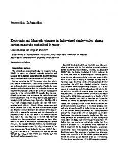
Figure S1. (a) Electrode current recorded during reduction of a 2.5 cm x 2.5 cm piece of CuOHNs-600C at −0.4 V vs. RHE in 0.1 M KHCO3 purged with Ar gas. (b) X-ray diffraction pattern collected on Cu-HNs-600C.
S-4
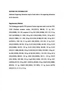
Figure S2. Typical CVs taken over a range of scan rates in a potential region where no Faradaic process is involved. (a) The scan rate is 2, 5, 10, 20, 40, 60, 80, 100, 125, 150, 175, 200, 225, 250, 300 and 350 mV/s, respectively. (b) Plot of the double-layer width from (a) against the scan rate, with the slope giving the capacitance.
S-5
Table S1. Summary of the surface roughness factors estimated for the Cu-HNs. Capacitance(mF/cm2)
Surface Roughness Factor in reference to Cu-poly
Cu-poly Disk
0.12
1
Pristine Cu Foam
4.43
36
Cu-HNs-500C
44.35
358
Cu-HNs-600C
76.52
637
Cu-HNs-700C
40.59
328
Sample
S-6
Figure S3. Schematic of electrochemical device using for electrolysis measurements.
S-7
Supplemental Electrocatalytic Results
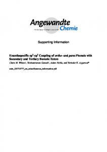
Figure S4. Tafel plots of the CO-production partial current densities for the Cu-HNs in comparison to the previously reported ECR Cu mesh.1
S-8
Table S2. Total geometric current density towards CO2 reduction products (jTCP) and faradaic efficiencies for each CO2 reduction product for Cu-HN-600C. Faradaic Efficiency (%) E V vs RHE -0.20 -0.25 -0.30 -0.35 -0.40 -0.45 -0.50 -0.55 -0.60 -0.65 -0.70
jTCP mA/cm 0.2 0.5 1.0 1.7 3.3 3.8 7.6 9.2 14.5 19.7 20.3
2
CO 39.8 53.6 59.8 53.5 52.1 51.8 43.4 35.1 28.6 18.9 17.4
HCOO H 0.0 0.0 0.0 6.9 11.0 20.1 26.8 33.4 31.3 45.9 39.9
C2H CH4 0.0 0.0 0.0 0.0 0.0 0.0 0.0 0.0 0.0 0.0 0.0
EtOH 0.0 0.0 0.0 0.0 0.0 0.0 4.7 5.0 4.7 5.0 4.8
C2H4 0.0 0.0 0.0 0.0 0.1 0.2 0.2 0.3 0.7 0.7 0.9
6
0.0 0.0 0.0 0.0 0.2 0.2 0.3 0.5 1.2 2.2 2.7
1PrOH 0.0 0.0 0.0 0.0 0.0 0.0 0.0 0.0 0.0 0.0 0.0
S-9
Calculation of the CO2 Conversion Rate CO2 conversion rates were calculated using the following equation:
(81)
𝐶𝐶𝑂𝑂2,𝑐𝑐𝑐𝑐𝑐𝑐𝑐𝑐
𝑛𝑛
𝑗𝑗 𝐹𝐹𝐹𝐹𝑖𝑖 = � � � 𝑛𝑛𝑖𝑖 , 𝐹𝐹 𝑧𝑧𝑖𝑖 𝑖𝑖=1
(1)
where CO2,cons stands for the rate of CO2 consumption (mols s-1 cm-2), j is the current density (A/cm2geo), F is faraday’s constant, ni is the moles of CO2 consumed per mole of product i, FEi is the faradaic efficiency of species i and zi is the number of electrons transferred per molecule for i.
S-10
References (1) Raciti, D.; Livi, K. J.; Wang, C. Highly Dense Cu Nanowires for Low-Overpotential CO2 Reduction. Nano Lett. 2015, 15, 6829–6835. (2) Bax, A.; Davis, D. G. MLEV-17-Based Two-Dimensional Homonuclear Magnetization Transfer Spectroscopy. J. Magn. Reson. 1969 1985, 65, 355–360.
S-11