(Spitfire Pro, Spectra Physics) delivering 120 fs, 2.5 mJ pulses at 800 nm. The white-light continuum used as a probe beam was generated by focusing a small ...
Supporting information to:
Ultrafast energy transfer between disordered and highly planarized chains of Poly[2-methoxy5-(2-ethylhexyloxy)-1,4-phenylenevinylene] (MEH-PPV) Thomas Unger†,‡, Fabian Panzer†,‡, Cristina Consani#, Federico Koch#, Tobias Brixner#,ǁ, Heinz Bässler‡, Anna Köhler†,‡,*
†
Experimental Physics II
University of Bayreuth, 95540 Bayreuth, Germany
‡
Bayreuth Institute of Macromolecular Research (BIMF)
University of Bayreuth, 95440 Bayreuth, Germany
#
Institut für Physikalische und Theoretische Chemie, Universität Würzburg,
Am Hubland, 97074 Würzburg, Germany
ǁ
Center for Nanosystems Chemistry (CNC), Universität Würzburg, Am Hubland,
97074 Würzburg, Germany
S1
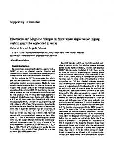
1. Description of the transient absorption setup with excitation at 2.1eV Transient absorption measurements with excitation at 2.48 eV were performed with a 100 kHz setup, consisting of a RegA9000 regenerative amplifier system from Coherent that delivered pulses, centered at 800 nm with a pulse width of about 190 fs as confirmed by an autocorrelator. 12% of the intensity was used to create the probe light externally in a YAGcrystal in the range from 480 to 1300 nm. The remaining intensity pumped a dual-pass optical parametric amplifier to produce the excitation pulses in the range from 2.48 eV to 2.0 eV. The pump beam diameter was about 200 µm to ensure homogeneous excitation. For the measurements, the pump pulse fluence was set to about 10 µJ/cm2, at which the pump-probe signal was linear with fluence (see Figure S1). Spectra were recorded using a lock-in amplifier and a monochromator with a silicon diode. 180
Probe Signal @ 2.34eV 300K
T (µV)
160 140 120 100 80 60 6
8
10
12
14
16
18
20
2
Fluence (µJ/cm ) Figure S1: Pump-probe signal as a function of fluence, probed at an energy of 2.34 eV.
For the transient absorption measurements exciting at 2.1 eV, the sample was filled in a 0.3 mm thick cell and placed in a continuous-flow cryostat (Oxford Instruments) operated with liquid nitrogen. The 42 fs excitation pulses at 2.1 eV were generated by a commercial parametric amplifier (TOPAS, Light Conversion), pumped by the output of a 1 kHz regenerative amplifier (Spitfire Pro, Spectra Physics) delivering 120 fs, 2.5 mJ pulses at 800 nm. The white-light continuum used as a probe beam was generated by focusing a small fraction of the 800 nm pulses in a CaF2 window. Pump and probe diameters at the sample position were 50 μm and
S2
30 μm, respectively. Also in this case, we used excitation-pulse energies (1.8 nJ) within the linear regime of excitation, where exciton-exciton annihilation processes are negligible.
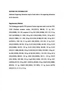
2. Changes of steady-state absorption and emission spectra as a function of temperature The relative change of area under the measured emission spectrum was normalized to the area under the measured spectrum at a temperature of 300 K. Upon cooling down to 180 K, the area continuously increases and finally triples at 180 K (Figure S2a). Spectral shifts of emission and absorption spectra were determined by considering the energetic position of the S1-S0 0-0 peaks. In emission this was easily possible within the whole measured temperature range. In contrast to that, simple determination of the S1-S0 0-0 peak from the spectrally unresolved
a)
3.0 2.5 2.0 1.5 1.0 180
200
220
240
260
280
S1-S0 0-0 Peak Position (eV)
Relative change of area
absorption spectra of the disordered phase was not possible (Figure S2b). 2.24
b) 2.20 2.16 2.12 2.08 Absorption Emission
2.04
120 140 160 180 200 220 240 260 280 300
300
Temperature (K)
Temperature (K)
Figure S2: (a) Relative change in area under emission spectra, normalised to the area at 300 K. (b) Energetic position of the S1-S0 0-0 peaks of the aggregated phase (< 180 K) and disordered phase (>180 K).
S3
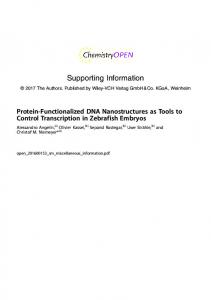
3. Calculating the fraction of aggregates from absorption spectra The fraction of aggregated chains
where
as a function of temperature is calculated by
is the fraction of aggregate absorption from the measured absorption spectrum
and F is the relative change of oscillator strength between disordered and aggregated chain conformation. We derived the relative change in oscillator strength between the aggregated and disordered phase,
, similar to the approach which is described in
detail in the supporting informations of previous works by Clark et al.1 and Scharsich et al.2, using
with the areas taken from the shaded regions as illustrated in Figure S3.
Absorption
2.0
3.3
Adisordered
2.8
1.6
2.2
1.2
1.7
0.8
1.1
Aaggregate
0.4
(x104 cm2 mol-1)
2.4
0.6
0.0
0.0 2.0
2.2
2.4
2.6
2.8
3.0
Energy (eV)
Figure S3: Exemplary illustration of the procedure to determine the change in oscillator strength between coiled and aggregated phase of MEH-PPV. The required areas Adisordered and Aaggregate are highlighted.
S4
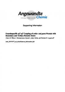
From this approach, the relative change in oscillator strength between disordered and aggregated phase can be obtained within the temperature range between 180 K and 140 K, which is found to be near unity (Figure S4).
Aaggregate / Aamorph
1.10
1.05
F= 0.98 0.01
1.00
0.95
0.90 140
145
150
155
160
165
170
Temperature (K)
Figure S4: Relative change of oscillator strength between disordered and aggregated phase as a function of temperature.
S5
4. Transient absorption spectra Energy (eV) 1.7 0.06
1.8
1.9
2
2.1
2.2
2.3 2.4 2.5
2.1
2.2
2.3 2.4 2.5
0.5ps
0.05 total signal SE GSB disordered GSB planarized
T/T
0.04 0.03 0.02 0.01 0.00 0.05
10ps
T/T
0.04 0.03 0.02 0.01 0.00 0.016
100ps
T/T
0.012 0.008 0.004 0.000 1.7
1.8
1.9
2
Energy (eV)
Figure S5: Pump-probe spectra for excitation at 2.48 eV (where coiled chains absorb) at 120 K for different time delays after excitation, i.e. (a) 0.5 ps, (b) 10 ps and (c) 100 ps. In addition to the total T/T signal (dots), the contributions of SE, GSB from disordered chromophores and the GSB from the planarized chromophores are indicated by orange, blue and red solid lines, respectively.
S6
5. Estimate of energy transfer range We will argue that the short timescale of energy transfer (< 1 ps) is not compatible with longrange energy transfer from coiled to planarized chains. Transfer from coiled to planarized chains is completed within 1 ps. Thus, a generous upper limit for the transfer rate
is 1x10¹² s-1.
Suppose the transfer takes place from a coiled chromophore to a planarized chromophore that are separated by a long distance . “Long”, in this context, in particular implies that the distance separating the centres of mass of the two chromophores is larger than their size. Thus, the point-dipole approximation applies. Let us suppose further that coupling between these chromophores is weak and that relaxation within S1 has occurred prior to energy transfer, so that the energy transfer can be presumed to be of a Förster-type nature. In the case of Förster-type energy transfer, the energy transfer rate another at a distance
is given by
, where and
from one chromophore to
(1)
is the lifetime of the donor chromophore in the absence of the acceptor chromophore is the Förster radius. The Förster radius depends on the mutual orientation of the two
chromophores, the refractive index of the surrounding medium, the fluorescence quantum yield of the donor chromophore and the spectral overlap between the donor emission and the acceptor absorption. Solving eq. (1) for
yields
.
(2)
For the lifetime of the donor chromophore we take a lifetime of 500 ps, which is typical for conjugated polymers3 and which is consistent with the data shown in Figure 5 in the manuscript. Typical Förster radii are in the range of a few nanometers, with 5 nm being a generous upper limit for
when all parameters are maximized.4
S7
Thus, an upper limit for the distance between the two chromophores is
1.8 nm. This
estimate demonstrates that energy transfer occurring on a picosecond timescale implies proximity between donor and acceptor chromophores. Addendum – Estimate of the maximum Förster radius of 5 nm: R0 is given by:4
with
being the dipole orientation factor,
the fluorescence quantum yield of the donor in
the absence of the acceptor, n the refractive index of the solvent medium, extinction coefficient of the donor and value of unity.
the molar
the donor emission spectrum normalized to an area
can at most be unity, and the refractive index cannot be lower than 1. For the
extinction coefficient of the donor we take a maximum constant value of 10 5 cm2 mol-1,5 i.e. we assume a step function. So far, all values have been assumed to take the maximum value that is allowed by theory. Let us presume that the overlap of donor and acceptor extends over a range of 100 nm, say, from 500 to 600 nm. Note that this is again a generous estimate and that typical values are smaller. Inserting these values into the above equation and carrying out the integral leads to R0=3.7 nm as maximum possible Förster radius. Thus, allowing for some margin, presuming a value of R0=5 nm is a generous upper limit.
References: 1. 2. 3. 4. 5.
Clark, J.; Chang, J.-F.; Spano, F. C.; Friend, R. H.; Silva, C. Applied Physics Letters 2009, 94, (16), 163306. Scharsich, C.; Lohwasser, R. H.; Sommer, M.; Asawapirom, U.; Scherf, U.; Thelakkat, M.; Neher, D.; Köhler, A. J Polym Sci Pol Phys 2012, 50, (6), 442-453. Ariu, M.; Lidzey, D. G.; Sims, M.; Cadby, A. J.; Lane, P. A.; Bradley, D. D. C. Journal of Physics: Condensed Matter 2002, 14, (42), 9975. Lakowicz, J. R., Principles of fluorescence spectroscopy. Springer US: 2006. See, e.g. Chapter 5 in Turro, N. J., Modern Molecular Photochemistry, University Science Books,1991
S8