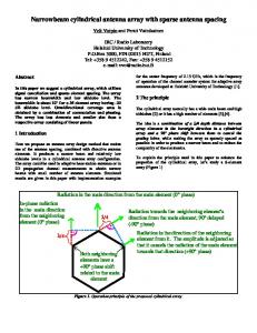
Switchable Disk-Loaded Monopole Antenna Array with CPW Feeding System M. R. Kamarudin1, P. S. Hall1, F. Colombel2 and M. Himdi2 1
School of Electronic, Electrical and Computer Engineering University of Birmingham, UK 2 Institut d' Electronique et de Télécommunications de Rennes (IETR) Université de Rennes 1, FRANCE
[email protected] ABSTRACT A switched beam disk-loaded monopole antenna array has been demonstrated that uses a coplanar waveguide (CPW) feeding technique. The antenna is designed for 2.45GHz ISM band for on-body communications or WLAN base station applications. It has a gain of 6.7dBi and the input return loss bandwidth is about 10%. The simulation and measurement results show a very good agreement. INTRODUCTION Electrically switchable antennas are becoming the most important feature of modern applications. Recently, switched parasitic monopole antenna arrays and electrically steerable passive array radiator (ESPAR) antennas have been described in detail in [1] and [2] respectively, in which the antenna beam can be tilted by isolating one of the parasitic element or by utilising a switching circuit. These methods are important especially for antennas used for on-body communications systems or wireless LAN antennas to reduce the multipath or interference between the signals as well as to minimise the battery consumption. Consequently, a disk-loaded monopole array antenna as shown in Figure 1, has been demonstrated in [3]. However, the advantages of CPW control have attracted many researchers [4-5]. One of the CPW advantages is that the integration between the antenna and the active devices such as pin diodes, MEMS and capacitors become more easy and practical to implement. It also provides less dispersion, low radiation loss and better impedance matching. These benefits have motivated to design a new disk-loaded antenna array which is fed by CPW. ANTENNA DESIGN Figure 1 shows the coaxial-fed disk-loaded monopole array antenna. The antenna consists of five disk-loaded elements in which the driven element is located in the middle of the antenna. Figure 2 illustrates the antenna array fed by CPW. The material type used for this antenna is RT/Duroid 5880. The dielectric thickness is 0.8mm and the dielectric constant, εr is 2.2. The interesting feature of this antenna is that the parasitic element configuration is controlled by a quarter wavelength CPW. For instance, when one end of the CPW is connected to the ground, the infinite impedance is transformed to the other end. As a result it looks like an open circuit and the monopole will act as a director and vice versa. From
the figure, it can be seen that three of the parasitic elements are reflectors while the remaining is a director.
Figure 1: Coaxial-Fed Antenna
Figure 2: CPW-fed Antenna
The CPW width and gaps are the most critical features of the antenna. In order to design this antenna, the CPW impedance is chosen to be 50Ω impedance for both driven element and parasite elements. The antenna dimensions are listed in Table 1. The distance between the driven element and its parasite is 27mm. Components CPW ground plane size CPW-driven element(width of strip) CPW-driven element(gap) CPW-parasite element(width of strip) CPW-parasite element(gap) Driven disk radius Parasite disk radius Height of elements (rod and disk) Driven and Parasite Rod Radius
Unit in mm 50 x 50 2.10 0.50 2.32 1.00 13.00 12.35 10.00 3.00
Table 1: Antenna Dimensions
ANTENNA RESULTS Figure 3 illustrates the antenna input return loss for both measurement and simulation. It clearly shows that good agreement between the simulated and the measured results has been achieved. From the figure, the fractional bandwidth for reflection coefficient below 10dB is about 10% (from about 2.37 GHz to 2.61GHz) which covers 2.45GHz ISM band.
Figure 3: Antenna Input return Loss
Figure 4: CPW-fed Antenna radiation pattern (E-Plane at φ = 450) (A and B respectively on both plots are same direction)
Antenna radiation patterns for both measurement and simulation are shown in Figure 4 and 5. From Figure 4, it can be seen that the beam is tilted above the planar board by about 400 in φ = 450 plane. The gain at this point is about 6.7dBi. Meanwhile, the gain of the opposite side is about 1.7dBi. By comparing this result with the results in [3], this pattern is much better because it produces more gain in open-circuiting element direction and lowers the opposite beam peak. Reference [3] has a predicted gain for open circuited element direction of 4.4dBi and its opposite is 4.0dBi.
Figure 5: CPW-fed Antenna radiation pattern (H-Plane)
Thus, the gain difference between two peaks has been improved by about 5dBi. Figure 5 shows the H-Plane pattern of the antenna. From the figure, it can be observed that two main lobes occur in the position of open circuited parasite and its opposite element. CONCLUSIONS A disk-loaded monopole antenna array fed by CPW feeding technique has been discussed for switched beam control. The antenna produce good input return loss covering the 2.45GHz ISM band and good agreement between the simulated and measured results. The antenna has a gain of 6.7dBi which is the peak radiation in the open circuited elements and is elevated above the ground plane by about 400. This design has improved the antenna patterns in [3] by about 2.3dBi of gain. The second peak of the radiation is expected to be caused by the horizontal current which flows in the disks. Much better patterns have recently been achieved when slots cut in the parasite top loading disks in the radial direction are used. REFERENCES 1 2 3 4 5
Schlub, R., and Thiel, D. V.: ‘Switched parasitic antenna on a finite ground plane with conductive sleeve’, IEEE Transaction on Antennas and Propagation, vol 52, issue 5, May 2004, pp. 1343-1347 Kawakami, H., and Ohira, T.: ‘Electrically steerable passive array radiator (ESPAR) antennas’, IEEE Antennas and Propagation Magazine, vol 47, issue 2, April 2005, pp. 43-49 Kamarudin, M. R. and Hall, P. S.: ‘Disk-Loaded Monopole Antenna Array for Switched Beam Control’, Electronics Letters, vol 42, issue 2, Jan 2006, pp. 66-68 Elsadek, H. A.: ‘CLIP Antenna for wireless Bluetooth applications’ IEEE Antennas and Propagation Magazine, vol 47, issue 3, June 2005, pp. 149153 Row, J. S.: ‘A simple impedance-matching technique for patch antennas fed by coplanar microstrip line’, IEEE Transaction on Antennas and Propagation, vol 53, issue 10, Oct 2005, pp. 3389-3391