The execution of program plans on concrete data for debugging during design ..... Program Construction Techniques, McMillan, I984, Chap. 10, pp. 201-222. 3.
SYMBOLIC EXECUTION IN ALGORITHM DESIGN David Steier and Elaine Kant1 Department of Computer Science Carnegie-Mellon University Pittsburgh, Pennsylvania 15213
Abstract
A Introduction Our studies of how people design algorithms [14,15] reveal that symbolic execution is one of the principal design methods used in the absence of specific knowledge,3 and we believe that symbolic execution will play an equally important role in the automatic design of algorithms. When specific design knowledge indicating what to do next is available, it should of course be followed. In its absence, however, executing an incomplete design allows an assessment of the consequences of the current set of design decisions to help decide on a next step. This execution may be either on specific data such as {point E, point B}, on abstract symbols such as "point-set," or on combinations of specific and abstract objects. By symbolic execution we mean the process of describing outputs in terms of inputs that are primarily abstract rather than concrete symbols. However, a continuous range of evaluation from wholly symbolic to wholly concrete falls under this heading, and all variants make contributions to the design process. When all items are concrete data values, we refer to the evaluation process as test-case execution. 1
Elaine Kant is currently at Schlumberger-Doll Research, Old Quarry Road,
Ridgefield , CT 06877. 2 This research was supported in part by the Defense Advanced Research Projects Agency (DOD). ARPA Order No. 3597, monitored by the Air Force Avionics Laboratory under Contract F33615-81 -K-1539, and in part by the National Science Foundation under Grant DCR-8412139. The views and conclusions contained in this document are those of the authors and should not be interpreted as representing the official policies, either expressed or implied, of the Defense Advanced Research Projects Agency, the National Science Foundation, or the U.S. Government. 3
O u r studies are supported by additional research on the human design of computer systems [1].
Symbolic execution, also called symbolic evaluation, has been studied as an independent software engineering tool for use after a program is written, but until recently little work has extended and integrated it into tho problem solving processes in design.4 In this paper, we focus on symbolic execution in design by describing our model of algorithm design, a system that implements that model, and illustrate the use of symbolic execution in a detailed example. Most of the early research on symbolic execution focused on execution or evaluation of complete programs to aid in testing, debugging, and verifying conventional languages. Some more recent work considers evaluating, analyzing, and explaining higher level specification languages This related work is discussed in Section E Since our primary interest is automating algorithm design, we operated independently of these efforts, although similar concepts appear in our system. We developed a model of algorithm design based on the analysis of some fifteen protocols of subjects designing geometric algorithms. The model underlies the implementation of an automatic algorithm design system we call DESIGNER [16]. Symbolic execution in this model shares a number of concerns with traditional symbolic execution: serving as an inexpensive test process that effectively executes multiple inputs simultaneously; creating symbolic representations of outputs as functions on inputs (useful for generating invariants and formally verifying programs or algorithms); describing the conditions for following each path to detect non-executable segments and to define subdomains of the input; indicating coverage of concrete test data and helping to generate additional tests. We are concerned also with symbolically executing procedures efficiently (not by macro substitution). The features of DESIGNER that differ from most other systems and modify symbolic execution for design purposes are: 1. DESIGNER executes incomplete algorithms in a dataflow language rather than requiring a full program in a procedural language. 2. Failures in symbolic execution lead to the posting of difficulties. Other problem-solving processes in the system use this information to correct errors in the design automatically. 3. The data objects in DESIGNER may be arbitrarily complex structures (e.g. geometrical objects or sets). In contrast, most symbolic interpreters allow only variables subject to conjunctions of numerical constraints, which are inadequate to represent many algorithms. (However, there is no guarantee that The execution of program plans on concrete data for debugging during design was however suggested a decade ago[24] The execution of plans in problem solving, which har, been more heavily researched, for example (9], is also related.
226
D. Steier and E. Kant
these more complex structures can be reasoned about satisfactorily in all cases.) 4 DESIGNER represents the results of multiple execution paths as disjunctions of conditionals on a single object rathei than requiring the user to specify the execution path(s) 5. Execution is controlled by assertions and rules rather than by a fixed interpreter, so it can be customized to serve a variety of design goals. 6. Multiple options in symbolic execution address a variety of design goals such as determining the run time of an algorithm, checking for consistency between adjacent steps in a design, and verifying that an algorithm produces the desired output. An initial implementation of symbolic execution embodying most of the principles described in this paper is operational in DESIGNER. Algorithms are represented as collections of object instantiations in a object-based system with a few simple forms of inheritance; symbolic execution operators are implemented in LISP; and symbolic execution control rules are written In the production-system language OPSS [10]. This implementation has symbolically executed algorithms in several task domains including geometric algorithms (such as finding the convex hull of a set of points), set operations, and numeric algorithms (such as Fibonacci and recursive factorial). Work continues on enlarging the set of geometric algorithms that can be represented and executed. B The Design Model In refining our model, we have concentrated on the following areas: definition of a dataflow representation for partial algorithm descriptions, implementation of operators for altering and executing the descriptions, collection of algorithm design heuristics in a number of task domains, specification of a subsystem for reasoning with visual images in geometric algorithm design, and development of a problem solving architecture for handling non-hierarchical goals effectively. Descriptions of this work have been published previously or will appear in future reports, so only the details needed to understand the role of symbolic execution are presented here. One driving force in this research is the formulation of the problem spaces [18] in which the algorithm design activity takes place. This requires a precise definition of the representations for algorithm design and of the operations used to manipulate these representations. It also requires definition of the problem spaces for the task domains (not discussed in this paper). The major algorithm problem spaces are design and execution. The spaces share the same basic representation, but address different types of problems and make use of different operators. In the design space, the states are partial descriptions of algorithms. The current design state is elaborated by the application of design operators (that edit algorithm descriptions) until a satisfactory specification is obtained (satisfactory is defined dynamically by the design rules). The algorithm modification process is guided by rules that describe what operators to apply to change the partial algorithm description; the rules have conditions that determine their applicability to the current state. If the search control knowledge is not sufficient to select a design operator, the problem solver sets up a subgoal to obtain this knowledge. The subgoal is usually satisfied by problem solving in another space, often the execution space.
Execution is an information-gathering strategy that executes the current description of the algorithm on symbolic or actual data objects to expose problems or opportunities for refinement. In the execution space, the partial description of an algorithm is fixed, and the data objects change in structure and position to yield the different states. If execution on symbolic data doesn't produce enough information for further refinement, or if a concrete validation of the algorithm is desired, then a concrete example is generated, actual data items are substituted for the symbols. Symbolic execution is preferable to test-case execution in many cases. For example, it amasses more complete information for verification, and it may be better to use a description such as "integer less than 10" than actually to pick one, when the system is looking for a counter example or example and doesn't have all the constraints on an object yet. However, symbolic execution can be more expensive if considerable expression simplification is required. Furthermore, discoveries caused by the combination of unexpected assertions and previous experience are more likely to result from working with concrete examples than from abstract reasoning based on the results of symbolic execution. C Representing Algorithms for Design and Execution We have developed a language called AL (Algorithm Language) for representing algorithms during the design process.6 Some key features of this representation, which distinguish it from similar representations (such as the plan calculus of the Programmer's Apprentice [19, 26, 20]), are its data-flow character, the fact that control flow can be defined implicitly by data-flow links rather than control-flow links (with a few exceptions), and the small number of initial built-in processes. Also, in the Programmer's Apprentice, all loops must be expressed as recursive calls, while in AL they can be expressed iteratively. In AL. the spectrum of description levels, from kernel ideas to fully refined algorithms, is easily represented. A consequence of this representation is that concern with the representation of data objects is largely absent initially (except in algorithms that rely on special data structures) in favor of elaboration of the processes manipulating data objects. In developing AL, we tried to identify a set of algorithmic objects that correspond closely to the conceptual building blocks our subjects use. We call such blocks components. Components are connected by links between ports (for input or output) of the components. A few basic component types are assumed, and the processing of a component may be modified by assertions on the component. New components may also be defined at any time in terms of other components and assertions. Our assertional language is a variant of first-order predicate calculus that can express the state of computations over time. A collection of components, links, ports, and assertions grouped together forms a network called a configuration. Configurations are the partial algorithm descriptions. This framework is not the basis for a "pure" data-flow representation. Our goal is to use objects that occur naturally as algorithmic steps, not a minimal set of primitive components. To avoid proliferation of object types, a design idea is initially represented as a component of approximately the right type with descriptive assertions. As design proceeds, any component 5 The level of detail in AL approximates that which people use to describe algorithms to one another. We do not claim that AL is an exact cognitive model for human algorithm design, only that the character of the language Is useful for automated design.
D. Steier and E. Kant
representing a complex process that does not correspond directly to a single primitive action may be refined into a complete configuration called a refinement configuration. This ability to refine components into sub-configurations along with the ability to define new concepts by adding assertions to simpler concepts provides a natural abstraction mechanism in AL. Only a brief overview of AL'S type hierarchies of components, ports, links and assertions will be given here since a detailed language description is the subject of another report in preparation [22].
227
increasing order, a particular test places its input numerical item on the true-exit port if the value of the item is greater than one. Configurations are executed (in the execution problem spaces) on items. Items are data objects that are passed between components and stored on links. Items have associated domains, such as geometry and arithmetic. Several items may be grouped together into a collection (which correspond to mathematical sets or sequences). Items may represent concrete objects or symbolic objects.
• Components: In AL, active process components represent steps in algorithms: algorithms are generic procedures to be refined; applies create new data based on their inputs; selects extract an element from an input collection; recursive-calls apply a process recursively; tests conditionally alter the data flow; compares report the relationship between two items and generators produce individual items from a collection in any specified order. Another type of component is the memory, which holds a representation of an object or collection. Generators cause certain components to be repeatedly executed. As the algorithm design proceeds, it may be necessary to represent this repeated computation explicitly, which we do with a loop box We classify the computation in a loop into separate configurations by function, the initialization, the loop-body, the repetition and the termination. All parts of a loop-box are optional (although the absence of an essential part may lead to a semantically incorrect design) During refinement, it is expected that some of the paits will be empty.
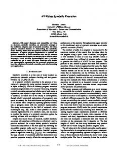
An example of a configuration representing a partially refined convex hull algorithm6 is given in Figure 1. The specification given to the subject is to find the convex hull of a set of input points where a convex hull is defined as either a polygon made up of a subset of the input points that encloses all the input points or the set of points on that polygon. This ability to view the output as either a set of points or a polygon turns out to be important during the design. The Inside predicate that defines enclosure is defined in the geometry space (it assumes that a point on the boundary of a polygon is inside the polygon) It is not necessary for the discovery that Inside be defined by logical assertions as long as there is a domain space operator to recognize examples of enclosure. The assertion is written as follows:
• Ports. Input ports and output ports represent data inputs and outputs of components, while signal ports serve control functions on specific component types, such as resetting a generator.
The configuration of Figure 1 represents an intermediate state in an initial attempt to get a working algorithm without using sophisticated design principles. The derivation is similar to one followed in a protocol that we have studied closely. The kernel schema follows the transfer paradigm as described by Barstow [2] in which the points in the input set are generated by the producer and built into an output set by the consumer. During the previous part of the design (not described here) this kernel schema was refined into a loop. In the graphic representation of our language, all configurations belonging to the same loop are enclosed in the same loop-box in a special format: initialization at the left side, termination at the right side, and repetition along the bottom. On each iteration of the loop, the algorithm arbitrarily selects a point (in select S1) from the set of input points that have not yet considered (stored in memory M1), adds the point to the set of points found to be on the hull so far (stored in memory M2), and then tests if the expanded set could be included in the hull (in test T1). If the test returns false, then the point just added is selected (in select S2) and deleted from M2. Symbolic execution of the kernel schema led to an expectation (recorded as an assertion) of an algorithm linear in the number of input points. The linear expectation arises because the producer is expected to be executed at most once for each input point to produce all the
• Links: Links usually connect components or configurations at the same level of the hierarchy. Special kinds of links, vertical-input links and vertical-output links, connect components to their refinement subconfigurations. • Assertions: Assertions are classified in AL by the domain of the operations they describe, for example numerical assertions and geometrical assertions. When used in a data-flow configuration, each assertion instance is assigned a role in accordance with its use. Roles relevant to symbolic execution are operational assertion, to specify how a component's output is derived from its inputs; description, to describe a data item; precondition and postcondition, to assert that certain conditions hold before and after the execution of a component; and complexity, to state time or space required for the execution of a component. Other assertions specify constraints on the order of execution the algorithm's components. Some of these assertions are predefined as being relevant to execution of all instances of a given type; for example, all selects must have a composite object as one of their Inputs. Other assertions are added during the design phase to specific component instances; for example, a particular generator produces elements from its input collection in
In the diagrams below this relation will be abbreviated to Convex-hullOutput, Input).
The convex hull algorithm discovered by this subject is not s particularly efficient one. Many other convex hull algorithms have been developed, and the problem can be solved in N Iog N time.
228
D. Steier and E. Kant
points on the hull. The refinement has not yet been symbolically executed to analyze its run time, so the fact that this expectation is not fulfilled has not yet been discovered. We will continue this example in the next section. D Symbolic Execution in DESIGNER One way to view the design process in our model is to consider each modification of a design as the imposition of a new constraint on the behavior of the algorithm. To usefully guide refinement, the constraints imposed by altering one part of the configuration must be propagated since typically refinement of algorithms is strongly locally driven. The propagation of a constraint imposed by one part of an algorithm serves to focus attention on potential problems in development of other parts of the algorithm and to bring together new combinations of facts that may lead to additional opportunities. This selective propagation of configuration-derived constraints is driven by execution. Symbolic execution manipulates assertions on symbolic items that arrive on the input ports of a component to produce appropriate assertions on items on the output ports. The assertions on the output items describe the results of applying operations defined by the component and its operational assertions to the input items. Symbolic execution continually evaluates assertions and compares the results against expected values determined locally by the component being executed. If an expectation is violated, then a difficulty is posted to notify the rest of the system of the inconsistency. Knowledge of the inconsistency combined with search-control knowledge in the design space should guide the problem solver in selection of the next operator to apply. This process allows detection of interactions between components in a uniform and efficient manner. A more detailed description of the symbolic execution process may be found in another paper [23].
Here, we show how symbolic execution can be used to integrate a test predicate discovered in the domain space (geometry) into the current design and to notice that the algorithm is not linear, as was originally expected. Details of the discovery of the test predicate have been described elsewhere [15], and so will not be repeated here. The original goal was to find a test to determine if a point is on the hull, but the discovered predicate tests if a segment is not on the hull (a segment is not on the convex hull of a set of points if there are not points on both sides of the line segment). Therefore the system must modify the design to make use of the predicate. As a first approximation, the test is initially represented as an assertion on test T1. Operational-assertion (Test predicate) on T1: Points- both-sides{segment input, Input) Since this assertion has just been added to T1, T1 is symbolically executed to see if it is fully refined The first problem that is uncovered is that the inputs are not well defined, because the operational-assertion requires different input than is currently available First, there is only one input port, and there need to be two ports, so execution is suspended, and another port (we'll call the existing one P1 and the now one P2) is added. A link is attached to the new port and preconditions on inputs to the test are added to distinguish P1 and P2: Precondition on T1: Using execution in this manner to uncover problems is an important part of DESIGNER. When a configuration can not be successfully executed, a problem called a difficulty is posted in the form of a goal or subproblem to be solved (not necessarily in the design space) If the initial assertions are correct and the inference mechanism is correct and adequate, the configuration
{Input}
Assertions: Operational assertion (Selection criterion) on S1: Operational-assertion (Selection criterion) on S2; Description on Input: Description on Input, Output: Complexity on CH: Description on M1: Postcondition on M2: Postcondition on T1: Figu re
1: Fragments of a dataflow configuration for generating a sequence of hull points.
D. Steier and E. Kant
lat implements the specifications is causing the problem, so a ifficulty indicates that some element of the current configuration eeds to be altered or refined. The difficulties fall into a small umber of categories. Since the design rules need only cover lese few categories of failure, a few rules and a relatively simple roblem-solving architecture allow DESIGNER to make progress In tost cases, regardless of the task domain. To continue the example, when symbolic execution of T1 Is [tempted again, the precondition on the inputs to T1 are ompared to the descriptions of the input items. The clause in the recondition about P1 is not satisfied because the current link to 1 does not contain the entire input, only a subset of it. There is a esign rule that applies to this problem: If a precondition is not satisfied by an input link in the current design, and there is another output in the current configuration that will satisfy this precondition, then detach the input link from its present source and connect it to the desired output. When this rule fires, the link feeding P1 will be detached from M2 nd connected to Input. The other clause of the precondition is ill not satisfied though, since P2 is not connected to anything roducing a segment. The previous rule will not apply, since no sgment is present in the design. A new item must be created, hich means that a component with a useful operational-assertion lust be added to the configuration, but another rule does apply: If a precondition is not satisfied by a link attached to a port in the current design, but it is known that an apply component with an appropriate operationalassertion can create a component with the required output, then add an apply to the configuration with the required assertion and connect its output to the port described by the unsatisfied pre-condition. In this case, the post condition required is that the output of the pply is a segment This knowledge is used to find the perational assertion for the apply by searching the domain knowledge base of the system for an assertion with an appropriate ost-condition. This search suggests a draw segment as an ssertion. so apply A1 is added with a draw-segment assertion hich takes a head point and a tail point and produces the egment connecting the two points. Operational-assertion (Apply action) on A1: Draw-segment {point- input, paint-input)
In this example, since A1 has just been added, that component is symbolically executed to see if it is complete. Symbolic execution gain points out the difficulty that ports and links are missing from e segment-constructing component and collects information bout the inputs. One point that is available is the point produced y S1, so a link is added from S1 to A1. Unless directed otherwise, \e same input should not be used twice for the same component since that may produce only degenerate cases of the desired utput) so another point is needed. The description of Output ontains the fact that the output may be viewed as a polygon, so lat the process of finding a convex hull may be seen as building a olygon and possible polygon fragments may be constructed by repeated extension from the most recently added vertex, herefore, the other input to A1 is obtained by following the memory of the hull so far (M1) with a select component (S3) that ets the point most recently added. Operational-assertion (Selection criterion) on S3: Select- most- recently-added (polygon- input)
229
Execution of S3 and A3 proceeds correctly, but M2 must now be changed to a component that manipulates polygon fragments by adding and deleting segments rather than adding or deleting from a point set. This is done by changing the port types and description assertion on M2. Now M2. and T1 execute correctly, but DESIGNER notices that the output of the test T1 is a segment, and not a set of points as expected. But M2's delete-segment port requires a segment. This condition activates another design rule: When the descriptions on some item satisfy all the preconditions on some input port of a component, then add a link (if there isn't one already) from the port producing the item to the input port with the satisfied preconditions. So a link is added from TVs true-exit port to M2's deletesegment port. An "optimizing" rule now applies to this situation: If data can flow through two different paths at one level of a configuration, but the paths produce symbolic items with equivalent descriptions, then one of the paths is redundant and the more complex one may be deleted from the configuration. In this case. S2 is no longer necessary, so it is removed. The configuration resulting from all the changes described is shown in Figure 2 Further design will focus on the details of the initialization and termination of the loop, which were not previously addressed in refinement of the loop-body, but we will not describe this here. Another important feature of symbolic execution is the use of the active goal to limit the constraints propagated during execution. This promotes simplicity and efficiency and also defines a simple criterion for deciding when execution of a configuration is complete. For example, if the goal is to guarantee that the algorithm is correct, then symbolic execution is tantamount to a full formal verification in the data-flow language, a complete propagation of all constraints. If the goal is to analyze the efficiency of the algorithm, then only those constraints relevant to the time and space usage of each component are propagated. Since many of the constraints in the design are often irrelevant to the active goal, this selectivity limits the computation necessary for automated design.7 However, the development of a surprising assertion can change the active goal or modify the type of information collected during symbolic execution. Unless interrupted by another process, execution generally proceeds by depth-first search of the graph formed by the configuration, restricted by the semantics of the data flows and bounded In depth when a component is sufficiently understood for present purposes (possibly from previous execution). Symbolic execution terminates when an active goal is satisfied, a difficulty is encountered or if nothing remains to be executed. The design goals satisfiable through execution include: • Checking the consistency of the design, including checking for missing inputs or specific errors such as data-type conflicts between components. • Given actual test-case data for some or all of the input, applying the algorithm to the data to compare the resulting output items to expected values.
Other advantages of explicitly considering design goals In automated systems are explained in Mostow's survey of design research [17].
230
D. Steier and E. Kant
• Checking that the algorithm (or component) executed on symbolic data satisfies its specifications as indicated by its preconditions and postconditions and those of any subcomponents. In the extreme case this amounts to a full verification. • Analyzing the time complexity of the algorithm. We illustrate the use of execution for time complexity analysis using the convex hull example. Analysis proceeds by propagating constraints about the number of different items that may occur on links that force re-execution of certain components. This is equivalent to determining the size of the set of items on a link as a function of the size of the input, when considering the set as a temporal abstraction of all items that may flow on the link over the entire computation The repetition and termination parts of loops are especially important to this analysis. In this example, at a later point in the design, it is seen that M1 is reset H times, corresponding to the number of points on the hull, which means that the worst-case run time of this piece of the algorithm is (H H N T), where N is the number of points in Input and 7" is the time to execute T1 for each segment. Since the formulation of the test in the domain space requires comparing the input segment to each point in Input, the test takes time proportional to A/, so the total time is (XHN2). This violates the original expectation of linear time. However, the existing design rules suggest no way to remedy this problem without a complete change of algorithm. Currently, the flexibility needed to satisfy these goals in symbolic execution is provided by allowing a variety of processing options. More than one option may be active at a time. Which options are
activated depends on the reason for trying symbolic execution. In addition to implementing these options, we are also currently examining the issues related to repeated computation, since the presence of repeated computation in an algorithm causes difficulties for all current symbolic execution systems, and indeed for human programmers as well. The problem is due to an undetermined, and hence potentially infinite, number of execution paths to be considered. One approach that has been taken [4, 27] is to try to automatically derive and solve recurrence relations to express the behavior of loops without the need for repeated execution. People, on the other hand, usually recognize a correc* loop when a small number of test cases work, and we wish to capture this ability to recognize familiar patterns from the structure of the algorithm and from symbolic or test-case execution in our system. We are currently investigating an approach that shares some of the characteristics of temporal abstraction in the Programmer's Apprentice. If the number of iterations is not totally constrained as in symbolic execution, we execute each part of the loop once to check internal consistency and give the results to a set of rules that can recognize familiar configurations and results. Such rules could perform the temporal abstraction necessary to determine the behavior of a loop in the general case. E Related Work on Symbolic Execution Previous work on symbolic execution has focused primarily on the goals of testing (generating test data and exercising program paths) and verification, although debugging, understanding,
Assertions:
Figure 2. : Convex hull algorithm after changes (changed assertions in boldface)
D. Steier and E. Kant
explanation, and analysis also have been addressed. Here, we list the work in this area that is most relevant to algorithm design; a longer summary can be found in [23]. For a survey of the uses of symbolic execution for program testing specifically, see [6]. EFFIGY [8], SELECT [3], DISSECT [12], the EL1 evaluator [4] and ATTEST [5, 28] were some of the first systms to use symbolic execution for testing and verification Symbolic execution, in conjunction with other techniques, has also been used to analyze the run-time performance of simple programs [27,13] More recent work considers symbolic evaluation of specifications (rather than program code) to help in the development process: the partition analysis method [6]; KOKO [7], which symbolically evaluates GIST specifications and is used as the basis of an explanation system [25]; REASON [21], a component of the Programmer's Apprentice system (in addition to other MIT work on meta-evaluation in the context of the actors formalism [11, 29]). Finally, simulation, a process similar to symbolic execution, was identified (based on protocol analysis experiments) in a model of the human design process focusing on software systems rather than algorithms [1], F Discussion We have described a system that makes explicit the role of symbolic execution in the design process. We claim that execution has more uses than the testing and debugging applications described thus far; namely, that in uncovering opportunities for the refinement of a data-flow algorithm representation, execution is the principal method guiding design in the absence of specific knowledge. A standard set of difficulties combined with appropriate search control knowledge allows the automated selection of design operators even if the algorithm is incompletely described. The power and flexibility of this approach is being validated by our current work on writing derivations of complex algorithms (such as convex hull); the results of execution control the search in the design problem space.
Acknowledgements We thank Allen Newell, Brian Milnes and Andrew Peterson for comments on earlier drafts of this paper, and Mary-Anne Wolf for collecting many of the protocols. All of them have contributed in numerous ways to the ideas in and implementation of DESIGNER.
References 1. Adelson, D. and Soloway, E A Model of Software Design. In The Nature o! Expertise. Chi, Glaser and Farr, Eds., ?, in press. 2. Barstow. D. R. The Roles of Knowledge and Deduction in Algorithm Design. In Biermann, A. W. (editor). Ed., Automatic Program Construction Techniques, McMillan, I984, Chap. 10, pp. 201-222. 3. Boyer, R S., Elspas, B., Levitt, K. N. SELECT — A Formal System for Testing and Debugging Programs by Symbolic Execution. Proceedings of the International Conference on Software Reliability, 1975. 4. Cheatham, T.E., Holloway, G.H., and Townley, J.A. "Symbolic evaluation and the analysis of programs." IEEE Transactions on Software Engineering SE-5, 4 (July 1979). 5. Clarke, L.A. "A system to generate test data and symbolically execute programs." IEEE Transactions on Software Engineering SE-4t 5 (September 1976). 6. Clarke, L. and Richardson, D. J. Symbolic Evaluation Methods — Implementations and Applications. In Computer Program Testing, Chandrasekaran, B. and Radicchi, S„ Eds., NorthHolland, 1981, pp. 65-102.
231
7. Cohen, D. Symbolic Execution of the Gist Specification Language. Proceedings of the Eighth International Joint Conference on Artifical Intelligence, Karlsruhe, West Germany, August, 1983, pp. 457-462. 8. Darringer, J.A., and King, J.C. "Applications of symbolic execution to program testing." Computer 7 7,4 (April 1978). 9. Fikes, R., Hart, P., and Nilsson, N. "Learning and executing generalized robot plans." Artificial Intelligence 3 (1972), 251-288. 10. Forgy,C.L. OPS5 User's Manual. Tech. Rept. CMUCS-81-135, Carnegie-Mellon University, Computer Science Department, July, 1981. 1 1 . Hewitt, C.E. and Smith, B. "Towards a Programming Apprentice." IEEE Transactions on Software Engineering SE-1, 1 (March 1975). 1 ? Howden, W E. "Symbolic testing and the DISSECT Symbolic Evaluation System." IEEE Transactions on Software Engineering SF-3,4(July1977). 13. Kant, E.. Efficiency in Program Synthesis. UMI Research Press, 1981. 14. Kant, E. and Newell, A. Naive algorithm design techniques: a case study. Proceedings of the European Conference on Artificial Intelligence, Orsay, France, July, 1982. 15. Kant, E. and Newell, A. "Problem solving techniques for the design of algorithms." Information Processing and Management 20, 1-2 (Spring 1984). 16. Kant, E. and Newell, A. An automatic algorithm designer: An initial implementation. Proceedings of AAAI-83,1983. 17. Mostow, J "Towards Better Models of the Design Process." Al Magazine 6, 1 (Spring 1985). 18. Newell, A Reasoning, Problem Solving and Decision Processes: The Problem Space as a fundamental Category. Tech. Rept. CMU CS 79 I33, Carnegie Mellon University, Computer Science Department, June, I979. 19. Rich, C Inspection Methods in Programming. Tech. Rept. AI-TR GCM, MIT, June, 1981 (PhD thesis) 20. Shrobe, H.E. Dependency Directed Reasoning for Complex Program Understanding. Tech. Rept. AI-TR-503, MIT, April, 1979. (PhD thesis) 2 1 . Shrobe, H E. Explicit Control of Reasoning in the Pi ogrammer's Apprentice Proceedings of the Fourth Workshop on Automated Deduction, February, 1979. 22. Steier, D. M. A Language for Representing and Executing Partial Algorithm Descriptions. Tech. Rept. in preparation, Carnegie-Mellon University, Computer Science Department, 1985. 23. Steier, D. M. and Kant, E. The Role of Symbolic Execution in a Model of Algorithm Design. To appear in IEEE Transactions on Software Engineering. An abbreviated version also appears in the Proceedings of the Third International Workshop on Software Specification and Design, August, 1985. 24. Sussman, G. J.. A Computer Model of Skill Acquisition. American Elsevier Publishing Company, Inc., 1975. 25. Swartout, W. R. The GIST Behavior Explainer. Tech. Rept. ISI/RS-83-3, University of Southern California Information Sciences Institute, July, 1983. 26. Waters, R.C. Automatic Analysis of the Logical Structure of Programs. Tech. Rept. AI-TR 492, MIT, December, 1978. (PhD thesis) 27. Wegbreit, B. "Mechanical Program Analysis." Comm. ACM 78,9 (September 1975). 28. Woods, J.L.. Path Selection for Symbolic Execution Systems. UMI Research Press, 1982. 29. Yonezawa, A. and Hewitt, C.E. Symbolic Evaluation Using Conceptual Representations For Programs With Side Effects. Tech. Rept. AI-TR 399, MIT, December, 1976.