Izdebskaya et al.
Vol. 25, No. 1 / January 2008 / J. Opt. Soc. Am. A
171
Symmetric array of off-axis singular beams: spiral beams and their critical points Yana Izdebskaya, Vladlen Shvedov, and Alexander Volyar* Department of Physics, Taurida National V. Vernandsky University, Vernadsky Av. 4, Simferopol 95007, Crimea, Ukraine *Corresponding author:
[email protected] Received July 23, 2007; revised October 24, 2007; accepted October 25, 2007; posted November 2, 2007 (Doc. ID 85493); published December 19, 2007 We consider conditions of structural stability under which the array of singular beams preserves its topological structure and intensity distribution while slightly perturbing its intrinsic parameters. The orbital angular momentum of the array as a function of the array parameters is a characteristic function, and its extreme points correspond to stable and unstable array states. © 2007 Optical Society of America OCIS codes: 140.3300, 260.3160, 350.5030.
1. INTRODUCTION One of the crucial problems of singular optics [1] is the shaping of singular beams with appropriate features of optical vortices [2]. As a rule, the vortex-bearing beams exploitable in different optical devices (for example, for trapping, transportation, and rotation of microparticles [3,4]; for processing quantum information [5,6]; for nonlinear optical operations [7], etc.) need a specific distribution of optical vortices over the beam cross section. However, tight focusing or other external perturbations arising in the course of operations with the beam can radically reconstruct its initial structure [8–10]; i.e., the external perturbations can violate its structural stability. In our article we consider conditions of structural stability (or, vice versa, structural instability) of a symmetric array of singular beams with a specific distribution of optical vortices relative to different external perturbations. It is well known [11–13] that Hermite–Gaussian, Laguerre–Gaussian, and Bessel–Gaussian vortex beams do not change their structure under focusing or propagation. The same property is inherent in a whole constellation of recently revealed beams such as Helmholtz– Gaussian [14,15], helico-conical [16], generalized Gaussian [17], hypergeometric beams [18], etc. However, the structural properties of the individual beams are radically changed via combining them into on-axis [19,20] or off-axis [21–28] compositions that can lose their structural stability. From among the different of wave constructions, Abramochkin and Volostnikov singled out only those beams whose intensity distribution does not change to scaling and rotation under propagation and focusing [29–31]. These were called spiral beams. In particular, standard Hermite–Gaussian and Laguerre–Gaussian beams with a real argument represent a family of spiral beams (in contrast to paraxial beams with a complex argument, including Bessel–Gaussian beams). They showed 1084-7529/08/010171-11/$15.00
that a composition of spiral beams propagating along the same optical axis is also a spiral beam. In some cases, the spiral beams can be regarded as a composition of off-axis singular or nonsingular beams. However, authors have not touched upon the problem of structural stability of such spiral beams relative to their inherent parameters. Before considering the structural transformations of a spatial beam array, it is necessary to define the concept of structural stability of a light beam. In accordance with Poston and Stewart [32] and Berry and Upstill [33], a function that describes some physical system is structurally stable if a slight perturbation does not change the type and number of its critical points. The critical points in a singular beam are associated with optical vortices. Freund in [19,20] gave a detailed analysis of degenerate critical points (higher-order optical vortices) in two-dimensional wave fields via external perturbations. He showed different ways of splintering the degenerated critical points into a new set of critical points, including those with a lower-order degeneracy. Thus, the structural stability (or instability) of a system of singular beams has to be treated together with the perturbation affecting the system [32]. On the other hand, the notion of structural stability is tightly connected with one more fundamental notion—genericity [19,20,34]; that is a natural realization of a certain model of physical objects without additional tricks of experimentalists. From this standpoint all light beams bearing higher-order optical vortices are nongeneric ones because arbitrary external perturbations can turn the degenerated optical vortex into a set of singly charged vortices until the experimentalist make use of special technical tricks. However, such nongeneric beams are structurally stable ones, for example, relative to free propagation, focusing with ideal optical instruments and a large number of other special perturbations. It is such a reduced notation of structural stability that we will use later on. © 2008 Optical Society of America
172
J. Opt. Soc. Am. A / Vol. 25, No. 1 / January 2008
The aim of our article is to study different structural transformations of a symmetric array of off-axis singular beams, in particular spiral beams via variations of their intrinsic parameters, to analyze their orbital angular momentum and to discuss different experimental ways of producing structurally stable vortex-beam arrays. The paper is organized as follows: In Section 2 we consider an axially symmetric array of singular beams bearing optical vortices with different magnitudes of topological charges. We focus our attention on analyzing the critical points and structural stability of the array relative to variation of its intrinsic parameters without violating its axial symmetry. A transformation of the orbital angular momentum of the array via variations of its parameters and a connection of it with critical points are considered in Section 3. We have proposed ways of producing structurally stable beam arrays on the basis of light diffraction on a stack of dielectrical wedges [35,36]. However, a detailed characterization of the experimental implementation is beyond the scope of the current paper; therefore we will try to consider it in a future paper.
2. VORTEX-BEAM ARRAY A. Wave Field of the Array Let us consider a beam array comprising a set of N identical singular beams whose axes lie on the surface of a hyperboloid of revolution. An example of the array of three singular beams is shown in Fig. 1. Each individual beam in the array carries over a centered optical vortex with a topological charge equal to M 共 = ± 1兲 and has a waist radius w0 at the plane z = 0. The vortex centers are placed at the vertices of a regular polygon with the angle coordinate n = 共2 / N兲n 共n = 1 , 2 , . . . , N兲. Sticking to a paraxial approximation, we will consider also that the angle ␣ between the axis of an individual beam and a common axis z of the array is small; i.e., sin ␣ ⬇ ␣ and cos ␣ ⬇ 1 − ␣2 / 2. Let a new referent frame 兵xn , yn , zn其 be connected with an individual beam so that its origin is placed at the nth vertex of the polygon at the z = 0 plane and the zn axis is directed along the individual beam axis. We can write a coordinate transformation in the form x n = x ⬘ − r 0,
Fig. 1.
yn = y⬘ cos ␣ − z sin ␣ ,
Geometry of the vortex-beam array.
Izdebskaya et al.
zn = y⬘ sin ␣ + z cos ␣ ,
共1兲
where x⬘ = x cos n + y sin n and y⬘ = −x sin n + y cos n. In our approximation we can write the local radial coordinate rn = 共x2n + y2n兲1/2 and the longitudinal coordinate zn in terms of general cylindrical coordinates 兵r , , z其 with x = r cos , y = r sin , and r = 共x2 + y2兲1/2 in the form rn2 ⬇ r2 − 2rr0 cos n − 2r␣z sin n + r2o + ␣2z2 , zn ⬇ z共1 − ␣2/2兲 + ␣r sin n ,
共2兲
where n = − n, r0 is a radial coordinate of a polygon vertex. A particular solution to a paraxial equation for complex amplitudes,
冉
2 x
2
+
2 y
2
− 2ik
z2
冊
˜ = 0, ⌿ n
共3兲
can be presented in the coordinates 兵r , , z其 as ˜ ⬇ ⌿ n
1 Zn
冋
r exp共in兲 − C Zn
册 冉 M
exp − ik
rn2 2Zn
冊
,
共4兲
where Zn = zn + iz0, z0 = kw02 / 2, w0 is the waist radius, k is the wavenumber, and C = r0 + i␣z. The complex amplitude represents a Gaussian envelope in coordinates 共xn , yn , zn兲 with a centered optical vortex, while its topological charge is equal to M. The sign of the topological charge is defined by the value = ± 1. The wave field of an individual off-axis beam can be rewritten as ˜ 共r, ,z兲exp共− ikz 兲. ⌿n = ⌿ n n
共5兲
In addition, we will consider that 1 / Zn ⬇ 1 / Z, Z = z + iz0 in the paraxial approximation. Equation (5) shows that the coordinate transformation imparts an additional phase to each individual beam connected with a rotation of the referent frame 共x⬘ , y⬘兲 at the angle n in transformation (1). In fact, such a transformation in our approach is equivalent to a rotation of the individual vortex beam. In order to compensate the additional phase and to match all individual beams, let us multiply Eq. (5) by the function exp关in共l + M兲兴 (where the orbital number l = 0 , ± 1 , ± 2 , . . .. is responsible for the phase matching of the beams in the array). Thus, a state of the vortex-beam array can be characterized by three groups of rotation (see Fig. 1). The first group is associated with a beam tilt at the angle ␣. The wave vector k of each individual beam has an azimuthal component k. It is this component that provides the array with rotation as a whole. The second group is connected with a helical wavefront of each individual singular beam [1]. The third group is associated with a phase matching of individual beams in the array. The phase matching secures increasing (or decreasing) of the phase as we bypass the array axis in a manner similar to that in the individual vortex beam. Different combinations of these rotations define intrinsic features of the vortexbeam array. The scalar field of the array is written in the form
Izdebskaya et al.
Vol. 25, No. 1 / January 2008 / J. Opt. Soc. Am. A ⬁
N
⌿=
兺
⌿n exp兵i exp关in共l + M兲兴其.
Zn
册
M
⫻
M
兺a R Ꭽ
M
兺
ZM s=0
共− 1兲M−s
冉冊 M s
CM−srs exp共isn兲.
共7兲
as =
Also we can write in Eq. (4)
冉 冊
exp − ik
rn2
2Z
s 关mN+l+共M−s兲兴/2
s
ImN+l+共M−s兲共2R兲,
共14兲
s=0
where
1 =
exp兵i共mN + l + M兲其
m=−⬁
For the nucleus of the function ⌿n we have
冋
兺
⌿ = N⌿0
共6兲
n=1
r exp共in兲 − C
173
=
冉 冊冉 冊 冉 冊 冉 冊冋 册 冉 冊 M−s
C
M
−
s
M
−
s
Z
w0
s
Z
r0 + i␣z
M−s
z + iz0
w0 Z
s
,
exp共− ikzn兲 = ⌿0 exp兵A exp共in兲 + B exp共− in兲其exp关i共l + M兲n兴, 共8兲
Ꭽ=
R − ¯␣ R + ¯␣
=
,
z0 Z
冑¯␣2 − R2,
r R=
w0
.
Let us consider different types of vortex-beam arrays.
where
冉
⌿0 = exp −
kz0 2
冋
⫻exp − i
冊 冉
␣2 exp − ik
册
z0 共¯␣2 − R2兲 Z
2
r2 2Z
− ikz
冊
B. Array of Off-Axis Gaussian Beams
共9兲
,
1. Spiral Beams The array of nonsingular phase-matched beams can be derived from Eq. (11) provided that the topological charge of the individual beams is zero, M = 0: ⬁
A=i
R=
z0 Z
r0 w0
共R − ¯␣兲
r w0
¯␣ =
,
,
B=i
␣ ␣diff
z0 Z
共R + ¯␣兲
␣diff =
,
w0
,
.
共10兲
On the other hand, we can make use of the generating function relation in Eq. (8):
冋 冋 册册 2
⬁
1
x
exp
t+
t
=
兺 t I 共x兲, p
p
共11兲
p=−⬁
where In共x兲 is a modified Bessel function. Then we can rewrite Eq. (6) in the form M
⌿ = ⌿0
兺 s=0
冉 冊 兺冉 冊 r
as
Z
s ⬁
p=−⬁
A
p/2
B
Ip共2冑AB兲exp关i共p + s兲兴
兺 exp关i共l + 共M − s兲 − p兲 兴. n
共12兲
n=1
Taking into account properties of the geometric series [37], N
冋
兺 exp
n=1
=
再
i共l + M − p − s兲
2 N
n
册
N if l + 共M − s兲 − p = mN, m = 0, ± 1, ± 2, . . . , 0
elsewhere
exp兵i共mN + l兲其
冉 冊 R − ¯␣
R + ¯␣
共mN+l兲/2
冉
ImN+l 2
z0 Z
冑¯␣2 − R2R
冊
.
共15兲
We see that the wave field of the array is written down in terms of standard on-axis Bessel–Gauss beams [13]. It is convenient to characterize the state of such an array with the help of two numbers 兵N , l其 and two dimensionless parameters ¯␣ and R. Consider the influence of different parameters of the array on the field structure [38,39]. Expression (15) can be essentially simplified for the case: ¯␣2 ⬇ R2. By using the property of modified Bessel functions [37] I±n共x兲 ⬇ 共x / 2兲n / n! (for small x), we find ⬁
⌿ ⬇ N⌿0
兺
m=−⬁
exp兵i共mN + l兲其 兩mN + l兩!
Ꭽ共mN+l兲/2共R兲兩mN+l兩 . 共16兲
N
⫻
兺
m=−⬁
⫻
2 kw0
⌿ = N⌿0
r
冎
共13兲
we come to a final form of the wave function in Eq. (12):
The series in Eq. (16) represents superpositions of standard vortex beams with constant coefficients and consequently describes typical spiral beams [29] with intrinsic parameters ¯␣ and R. In fact, the condition: ¯␣2 ⬇ R2 demands that an overlapping of sidelobes of individual beams does not change during beam array propagation. The interference pattern does not change the intensity distribution, and, consequently, the structural construction of the spiral beam remains constant while propagating. The intensity distribution can revolve on the array axis; its scale can change but the number and type of critical points remain constant. Thus, we can simplify Eq. (16) by assuming z = 0:
174
J. Opt. Soc. Am. A / Vol. 25, No. 1 / January 2008 ⬁
⌿ ⬇ N⌿0共z = 0兲
兺
exp兵i共mN + l兲其
m=−⬁
兩mN + l兩!
Izdebskaya et al.
Ꭽ共mN+l兲/2共¯R兲兩mN+l兩 , 共17兲
where ¯ = 共R2 − ¯␣2兲1/2. However, variation of the intrinsic parameters ¯␣ and R can take the beam out of a stable state, changing the type and order of critical points. 2. Properties of the Beam Array The simplest example of the spiral beam is an array of two beams: {2, 1}. From Eq. (17) we obtain
冋兺 ⬁
⌿ ⬇ 2⌿0
m=1
⬁
+
兺
m=0
共R + ¯␣兲2m−1 共2m − 1兲!
共R − ¯␣兲2m+1 共2m + 1兲!
R2m−1 exp兵− i共2m − 1兲其
R2m+1 exp兵i共2m + 1兲其
册
= 2⌿0兵sinh关共R + ¯␣兲R exp共− i兲兴 + sinh关共R − ¯␣兲R ⫻exp共i兲兴其.
In the general case, the value and sign of the topological charge of the centered vortex are defined by a sign of a product 共␣l兲 and depend on a correlation between a number of individual beams N and an orbital number l: N ⬍ 2兩l兩 + 1 or N ⬎ 2兩l兩 + 1, if N ⬎ l. For example, the array of three beams N = 3 and l = ± 1 has the topological charge Q = ± 1 of the centered vortex (Fig. 2; {3, 1}), but as soon as l = ± 2, we obtain Q = ⫿ 1. However, as a beam array propagates along the z axis, its intensity distribution can dramatically change. Typical transformations of the intensity distribution (when the array parameters are far from critical ones R = 兩¯␣兩) are shown in Fig. 3(I). Near the initial plane z = 0, the vortex net of the array 兵5 , −2其, consisting of single-charged vortices with a double-charged vortex Q = 2 at the center, forms a typical pentagram. As the array propagates, the pentagram is distorted together with the intensity distribution. In contrast to that, the intensity distribution of the spiral beam 兩¯␣兩 = R with R = 1.8 in the same state [see Fig. 3(II)] does not experience any transformations but a scaling and a rotation.
共17a兲
The above equation describes the field with a chain of the optical vortices with a deformed core positioned on the y axis (Fig. 2; {2, 1}). As the parameters R → 兩¯␣兩, a contribution of oppositely charged vortices vanishes. When the value R diminishes, a distance between neighboring identically charged vortices grows so that we can observe the only centered optical vortex with a nearly ideal core. The same property has high-order beam arrays. The beam arrays with N = 2兩l兩 takes a specific place because neighboring individual beams in those have a phase difference equal to . There is not a central optical vortex if the beam axes are parallel: ¯␣ = 0. In the case ¯␣ ⫽ 0, the sign of the vortex topological charge does not depend on the sign of orbital number l being exclusively defined by the angle ¯␣.
3. Critical Points and Structural Stability of Spiral Beams Let us first consider structural transformations of the array field via variations of its intrinsic parameters: the relative angle ¯␣ and the relative displacement R. It is necessary to keep in mind that both ¯␣ and R comprise implicitly the waist radius w0 so that real variations of the angle ¯␣ and the displacement R are also accompanied by variations of the parameter w0. There are four possible states of the beam array depending on signs of the angle ¯␣ and the orbital number l: (1) ¯␣ ⬎ 0 , l ⬎ 0; (2) ¯␣ ⬍ 0 , l ⬎ 0; (3) ¯␣ ⬎ 0 , l ⬍ 0; and (4) ¯␣ ⬍ 0 , l ⬍ 0. The symmetry of the array enables us to reduce them to two states: (1) 共¯␣l兲 ⬎ 0 and (2) 共¯␣l兲 ⬍ 0. Let the beam array be characterized by an orbital num-
Fig. 2. Intensity distributions (I) and interference patterns (II) for the beam array in the state 兵N , l其 at z = 0 plane.
Fig. 3. Transformations of the intensity distribution of the beam array (I) and the spiral beam (II) in the state 兵5 , −2其 along the z axis.
Izdebskaya et al.
Vol. 25, No. 1 / January 2008 / J. Opt. Soc. Am. A
175
ber l ⬎ 0 so that N ⬎ 兩l兩, whereas the angle ¯␣ ⬎ 0. Then the field (17) for spiral beams 共兩¯␣兩 ⬇ R兲 has the form
冋兺 ⬁
⌿ ⬇ N⌿0
共R + ¯␣兲mN−l 共mN − l兲!
m=1
⬁
+
兺
m=0
共R − ¯␣兲mN+l 共mN + l兲!
RmN−l exp兵− i共mN − l兲其
册
RmN+l exp兵i共mN + l兲其 .
共18兲
The second sum in Eq. (18) vanishes if 兩¯␣兩 = R, the central vortex acquiring a topological charge Q = −共N − l兲. In the vicinity of the point 兩¯␣兩 = R, the central vortex surrounded by N single-charged optical vortices has a charge Q = l. Thus, the point 兩¯␣兩 = R (for all z axes) is a critical point of the order Q = −共N − l兲. In order to realize the behavior of the critical point, it is necessary to plot vortex trajectories near the axis R = 0 in coordinates 共x , y , ¯␣兲 under the condition that Re关⌿共x , y , ¯␣兲兴 = 0, Im关⌿共x , y , ¯␣兲兴 = 0. From Eq. (18), we find Rl exp共il兲
R
l!
exp关− i共N − l兲兴
+
+
共R + ¯␣兲N−l 共N − l兲!
RN−2l exp共− iN兲
N 艌 2l,
= 0,
N−l
冋
共R − ¯␣兲l
共R − ¯␣兲l l!
册
共19兲
冋
共R + ¯␣兲N−l 共N − l兲!
册
R2l−N exp共iN兲 = 0,
N ⬍ 2l.
共20兲
Thus, we have two types of vortex trajectories for the cases N ⬍ 2l and N 艌 2l separated by a critical value of the orbital number N = 2lcrit. The form of the trajectories is shown in Fig. 4. Trajectories in coordinates 共x / w0 , y / w0 , ¯␣兲 depicted in Fig. 4(a) represent a beam array in the state {3, 1} with R = 1 and N ⬎ 2l. A slight deviation of the angle
Q=
Q=
再 再
Fig. 4. (Color online) Vortex trajectories of the beam array in states (a) {3, 1} and (b) {4, 3} with R = 1.
¯␣ from the critical value 兩¯␣兩 = R = 1 entails splintering the centered vortex into three outlying vortices and one central vortex. In the general case, a number of outlying single-charged vortices equals N, whereas a residuary central vortex has a topological charge l. A perturbation 兩⌬¯␣兩 Ⰶ 1 causes an explosion of a critical point of the order Q = −关N − l兴, transforming it into a critical point of the order Q = l. A spiral beam in such states is a structurally unstable relative to a perturbation of its intrinsic parameters: the angle ¯␣ and the displacement R. An absolutely different situation occurs in the state with N ⬍ 2l 共l ⬎ 0兲. Figure 4(b) illustrates this case for the beam array in the state {4, 3} with R = 1. Any deviations of the angle ¯␣ from the critical value 兩¯␣兩 = R do not change the form of the vortex trajectories. The order of the critical point is equal to Q = −共N − l兲 for all ¯␣. Generally speaking, the vortex trajectories calculated on the basis of approximate expression (20) aspire to infinity at the plane ¯␣ = 1. But taking into account terms of the higher orders in Eq. (18), we obtain only a slight deviation of the trajectories at the plane ¯␣ = 1. We have studied all possible versions and combinations of signs between ¯␣ and l and have revealed the following simple rules for critical points and structural stability of spiral beams produced by the beam array in the state 兵N , l其:
− sign共¯␣兲共N − 兩l兩兲, 共¯␣l兲 ⬎ 0, structurally unstable spiral beams − sign共¯␣兲兩l兩,
共¯␣l兲 ⬍ 0, structurally stable spiral beams
− sign共¯␣兲共N − 兩l兩兲, 共¯␣l兲 ⬍ 0, structurally stable spiral beams − sign共¯␣兲兩l兩,
冎 冎
共¯␣l兲 ⬎ 0, structurally unstable spiral beams
In fact, structural instability of a spiral beam results from superposition of N + 1 vortices at the array axis: N negatively (positively) charged off-axis vortices and one positively (negatively) charged on-axis vortex with a topological charge equal to l. The on-axis vortex associated with the number l is a result of phase matching of individual beams in the array. It can arise at the beam axis even if the angle ¯␣ = 0. On the other hand, a major contribution in shaping outlying vortices proceeds from the destructive interference of two neighboring Gaussian beams
,
N 艌 2兩l兩,
¯␣ = R,
共21兲
,
N ⬍ 2兩l兩,
¯␣ = R.
共22兲
共¯␣ ⫽ 0兲. These beams form a chain of optical vortices whose signs of topological charges are opposite to that of the centered vortex if 共¯␣l兲 ⬎ 0. Changing the angle ¯␣ (or the displacement R) also changes the positions of off-axis vortices so that they are superposed at the center (provided that ¯␣ = R), forming a central vortex with 共N − 兩l兩兲 topological charge. Any slight variation in either the displacement R or the angle ¯␣ destroys the central vortex into N off-axis single-charged vortices and a central vortex with l topological charge.
176
J. Opt. Soc. Am. A / Vol. 25, No. 1 / January 2008
Izdebskaya et al.
When the angle ¯␣ and the orbital number l have opposite signs 共¯␣l兲 ⬍ 0, the central vortex and outlying vortices acquire the same signs of topological charges. All vortices cannot be gathered at the center for any ¯␣ and R. Thus a spiral beam becomes structurally stable. At the same time, the value of an orbital number N = 2兩l兩 can change the type of structural stability of a spiral beam. Indeed, values of the number l obeying the inequality N ⬎ 2兩l兩 correspond to increasing the phase of the field in the vicinity of the beam axis, while the inequality N ⬍ 2兩l兩 presumes that the phase decreases. This is equivalent to turning the condition 共¯␣l兲 ⬎ 0 into the condition 共¯␣l兲 ⬍ 0. However, spiral beams in the state 兵2兩l兩 , l其 are always structurally stable. However, notice that any perturbations of the beam symmetry cause decay of the higherorder optical vortex at the axis. 4. Array of Off-Axis Singular Beams Critical points in the array of singular beams display a series of new, unexpected features that were not inherent to that of Gaussian beams. In fact, the order of the critical point in the array corresponds to a number of intersections of a helixlike wavefront of individual beams at the axis. Naturally, this number depends on the number of beams N and the number of leaves in the helicoid (associated with a topological charge M of each individual vortex nested in the beam), whereas phase matching (defined by the index l) ensures shaping of the vortex at the array axis. Besides, the number of intersections is very sensitive to the beam displacement R and inclination ␣, which are responsible for phase tuning of the individual beams. A number of critical points in the vortex-beam array grow appreciably. To avoid excessive mathematical details, we will try to trace a total picture of structural instability of spiral beams from the example of the most instructive particular cases. The state of the vortex-beam array we will designate now as 兵N , l , M其. Case (I) ¯␣ ⬎ 0, l 艌 0, ⬎ 0 or case (II) ¯␣ ⬍ 0, l ⬍ 0, ⬍ 0 and N 艋 M + l. The wave function (14) for spiral beams: ¯␣ ⬇ R, z = 0 can be rewritten as ⌿ = N⌿0
再
⬁
兺
exp兵− i共mN − l − M兲其
m=1
RmN−共l+M兲+2s
M
⫻
兺
as共R + ¯␣兲mN−共l+M兲+s
s=0
共mN − l − M + s兲!
⬁
+
兺R
m⬘N+l+M
exp兵i共m⬘N + l + M兲其
m⬘=0 M
⫻
兺
s⬘=0
a s⬘
共R − ¯␣兲m⬘N+l+M−s⬘ 共m⬘N + l + M − s⬘兲!
冎
,
共23兲
rest of the cases is defined by the relations between the first and the second terms in Eq. (23). The second term in Eq. (23) vanishes for all ¯␣ and R if ¯␣ = R. Therefore, the critical point has the order Q = −关N − 共l + M兲兴. Any deviations from critical value ¯␣ = R destroy ␣⫽R
the critical point: −关N − 共l + M兲兴 → l + M, l ⫽ 0. A typical example is an explosion of the critical point for the array in the state {9, 2, 1}: The central optical vortex with topological charge Q = −关9 − 共2 + 1兲兴 turns into the vortex with Q = 2 + 1 and nine outlying vortices with Q = −1. Case l = 0, ¯␣ = R is of a particular interest. We find here new intrinsic features of the critical point. The field near the critical point R = 0 has the form
再
⌿ ⬇ N⌿0共iw0/z0兲M 共− 1兲N−MRN−M exp兵− i共N − M兲其 ⫻
共2R兲N−MRM 共N − M兲!
冎
+ Rl+M exp兵iM其 .
Both terms in Eq. (25) contribute to shaping the axial optical vortex. When N = 2M, the contribution of both terms in Eq. (25) is the same if Rcrit =
冑
冑MM! 2
⌿ ⬇ 2N⌿0共iw0/z0兲M cos M .
w0 z0
M
M
j =
2j + 1 M
2
,
j = 0,1, . . . ,M,
s
共28兲
in the vicinity of the array axis. Transition through the critical value of the displacement Rcrit (26) corresponds to changing the topological charge sign of the central vortex. Thus, we can point out at least two critical conditions of structural instability for the beam with a critical point Q = −关N − 共l + M兲兴. The first condition 兩¯␣兩 = R refers to a transformation of the beam array into a spiral beam via variation of both ¯␣ and R parameters. The second condition R = Rcrit = 兩¯␣crit兩 is connected with a conversion of the sign of the critical point in the spiral beam itself via variations of the only intrinsic parameter R. Case (II) ¯␣ ⬍ 0, l ⬍ 0, ⬍ 0. This differs from case (I) only in the sign of the critical point. Case (III): ¯␣ ⬍ 0, l ⬎ 0, ⬎ 0. The wave function (14) has the form ⬁
⌿ ⬇ N⌿0
兺
exp兵− i共mN − l − M兲其
m=1
⫻ 共− 1兲sRM−s .
共27兲
This means that the critical point of the order M turns into M rays,
M
冉 冊冉 冊
共26兲
,
and
where as = − i
共25兲
再
s=0
共24兲
First of all, it necessary to note that the central vortex disappears if N = l + M. The intensity distribution has a maximum at the axis. The order of the critical point in the
兺
as共R − ¯␣兲mN−l−共M−s兲
+
RmN−l−M+2s 共mN − l − M + s兲!
⬁
兺R
m⬘N+l+M
exp兵i共m⬘N + l + M兲其
m⬘=0
⫻⍜mN,l,M共R, ¯␣ + R兲其,
共29兲
Izdebskaya et al.
Vol. 25, No. 1 / January 2008 / J. Opt. Soc. Am. A
共R + ␣兲mN+l+M−s⬘
M
⍜mN,l,M共R, ¯␣ + R兲 =
兺 a ⬘共R兲 共mN + l + M − s⬘兲! . s
177
共30兲
s⬘=0
Under the condition 兩¯␣兩 = R, expression (30) can be written near the axis R = 0 as ⌿ ⬃ Rl+M exp兵i共l + M兲其⍜0,l,M共R兲 + RN+l+M ⫻exp兵i共N + l + M兲其⍜N,l,M共R兲.
共31兲
A major part in shaping the central vortex is played by the first term in Eq. (31) until the polynomial ⌰0,l,M共R兲 ⫽ 0 so that the order of the critical point is Q = l + M. In the case of ⌰0,l,M共R兲 = 0, the second term forms a critical point of the order Q = N + l + M. Since the polynomial ⌰0,l,M共R兲 has M roots, such structural transformations of the array are repeated M times via variations of the parameter R. Thus, we revealed that a spiral beam with a critical point Q = l + M is a structurally unstable one relative to the above-mentioned variations of its intrinsic parameters. Case (IV): ¯␣ ⬎ 0, l ⬍ 0, ⬍ 0. Notice that simultaneous change of signs in an orbital number l, a topological charge , and the angle ¯␣ to the opposite 共l , M , −¯␣兲 → 共−l , −M , ¯␣兲 does not change the structural state of the array field but turns the topological charge sign of the central vortex to the opposite: Q → −Q. Case (V): ¯␣ ⬎ 0, l ⬎ 0, ⬍ 0. This case has two versions. Version (V.1): ¯␣ ⬎ 0, l ⬎ 0, ⬍ 0, l ⬎ M. The wave function (14) can be written in the following forms: ⌿ = N⌿0
再
⬁
兺R
mN−共l−M兲
exp兵− i共mN − 共l − M兲兲其
m=1
⬁
兺
exp兵i共m⬘N + l − M兲其
m⬘=0 M
兺
s⬘=0
a s⬘
the
second
explosion
共R − ¯␣兲m⬘N+l−共M−s⬘兲 关m⬘N + l − 共M − s⬘兲兴!
冉 冊兺
⍜mN,l,−M共R, ¯␣兲 = − i
w0 z0
共¯␣ + R兲mN−l+M−s⬘
M M
s⬘=0
a s⬘
冎
Rm⬘N+l−M+2s⬘ ,
共mN − l + M − s⬘兲!
.
共32兲
共33兲
The second term in Eq. (32) vanishes if ¯␣ = R and does not contribute to shaping the critical point. The critical point has the order Q = −关N − 共l + M兲兴 until the polynomial ⌰N,l,−M共¯␣ = R兲 ⫽ 0. In the case of ⌰N,l,−M共¯␣ = Rcrit兲 = 0, the critical point gets the order Q = −关2N − 共l + M兲兴. A deviation from the condition ¯␣ = R entails changing the order of the critical point to Q = l − M. Intensity distributions and patterns of the phase shown in Fig. 5 represent successive transformations of the spiral beam structure via slight variations of the parameters ¯␣ and R. Polynomial (33) has the only root Rcrit = 2 for the spiral beam in the state 兵9 , 2 , −1其. The pattern of the field corresponding to the root represents the spiral beam carrying the only vortex with Q = −共2 · 9 − 2 + 1兲 = −17. A slight deviation from Rcrit, ⌬R = 0.05, results in the first explosion of the critical point ⌬R,¯␣=R
so that Q = −关2N − 共l + M兲兴 → − 关N − 共l + M兲兴 = −共9 − 2 + 1兲 = −8. A deviation from the condition ¯␣ = R gives rise to
of
⌬¯␣,¯␣⫽R
the
critical
point:
−关N − 共l + M兲兴 → 关l − M兴 = 1. Version (V.2): ¯␣ ⬎ 0, l ⬎ 0, ⬍ 0, l ⬍ M. The difference of the wave function from that in Eq. (32) is that the sum over s⬘ in the second term of Eq. (32) consists in two sums with factors 共¯␣ + R兲M−共l−s⬘兲 and 共¯␣ − R兲共l−s⬘兲−M. The critical 共j兲 parameter Rcrit under the condition ¯␣ = R is defined by the roots of the polynomial in the second term: M−l
共M−l兲 = ⍜0,l,−M
兺
s⬘=0
⫻⍜mN,l,−M共R,R + ¯␣兲 +
⫻
Fig. 5. Double explosion of the critical point in a spiral beam in the state 兵9 , 2 , −1其 with the intensity (I) and phase (II) distributions.
a s⬘
共R + ¯␣兲M−共l+s⬘兲 共M − l − s⬘兲!
共34兲
.
Therefore successive explosions of the critical point similar to those in version (V.1) are impossible. For example, for a spiral beam in the state 兵9 , 1 , −2其, polynomial (34) has only the root Rcrit = 1. A beam with such a parameter has a central vortex with Q = −共9 + 2 − 1兲 = −10. A slight variation of the displacement R under the condition ¯␣ ⌬R,¯␣=R
= R results in a transformation −关N − 共l + M兲兴 → M − l = 1. Case (VI): ¯␣ ⬍ 0, l ⬍ 0, ⬎ 0. We obtain results similar to those for case (V); however, Q turns to the opposite sign. Thus, it is impossible to give a general parametric relation for the structural stability of a vortex-beam array. Each particular case needs a detailed analysis. The first explosion of the critical point can accompany a transformation of the beam array into a spiral beam under the condition 兩¯␣兩 = R. We revealed that such a transition corresponds to structurally unstable spiral beams with a critical point Q = − sign共¯␣兲关N − 共l + M兲兴, 共l兲 ⬎ 0,
共¯␣l兲 ⬎ 0,
N 艌 2兩l + M兩.
Spiral beams in other states do not experience structural transformations. However, inside the condition 兩¯␣兩 = R, variations of the intrinsic parameters ¯␣ and R of spiral beams can stimulate a series of explosions of the critical point, resulting in structural transformations of the beam state. At the same time, a critical point is not a global characteristic of the beam array. Its decay can do little damage to properties of spiral beams. In the following sec-
178
J. Opt. Soc. Am. A / Vol. 25, No. 1 / January 2008
Izdebskaya et al.
tion, we will discuss the influence of a critical point explosion on the global characteristic of the spiral beam.
兵qm,s其 in the hypergeometric functions 3F3 stand for pm,s + 1 pm,s pm,s + s + s⬘ + 2 , + 1, ; 2 2 2
兵pm,s其 =
3. ORBITAL ANGULAR MOMENTUM The orbital angular momentum (OAM) [6] is a global characteristic of a beam array, with critical points playing a specific role in its inherent properties [21,38,40]. Optical vortices nested in the array cause energy to circulate around individual axes. On the other hand, an inclination of off-axis beams forces the energy flux to circulate around the array axis, too. Moreover, the phase matching of the beams leaves its additional imprint on the flux rotation. A mutual competition of these three circulation processes ensures shaping of a full OAM of the vortexbeam array (see Fig. 1). In this section, we will analyze the evolution of the OAM caused by variations of the array parameters, focusing our attention on a linkage between OAM transformations and explosions of critical points. In order to calculate the OAM Lz, we make use of a simple relation [41] for paraxial beams: Lz = Im具⌿兩/兩⌿典.
共35兲
By using Eqs. (14) at the plane z = 0 and the integral [42]
冕
x
0
exp共− px 兲I共cx兲I共cx兲dx 2
冉冊 冉
+
1 c =
1
⌫关共 + + 兲/2兴
2 2
共冑p兲++ ⌫共 + 1兲⌫共 + 1兲
⫻ 3F 3
++1 + ++ , + 1, ; 2 2 2
+ 1, + 1, + + 1;
c2 p
冊
− w02 2 ⫻
+
⫻
⬁
˜2 ⌿ 0
兺
M
共mN − l − M兲
⌫关共pm,s + s + s⬘ + 2兲/2兴
−! −! w02 2
兺
M
共mN + l + M兲
s,s⬘=0
m=0
⌫关共qm,s + s + s⬘ + 2兲/2兴
+! +!
兺
a sa s⬘ 2
qm,s
2
− ¯␣2兲兲
− w02 2
⬁
˜2 ⌿ 0
兺 共mN − l − M兲
m=1
⌫
M
⫻
兺
s,s⬘=0
a sa s⬘
冉
pm,s + s + s⬘ + 2 2 2pm,s−!−!
冊
共2R兲pm,s .
共38兲
2
− ¯␣2兲兲,
N 艌 l + M.
冉 冊 R − ¯␣
兺
mN+l
R + ¯␣
ImN+l共2关R2 − ¯␣2兴兲.
共39兲
It is very suitable to use the value of a specific OAM defined as
=
Lz 具⌿兩⌿典
.
⬇ − M − R¯␣ .
共R − ¯␣兲qm,s
3F3共兵qm,s其;4共R
for l + 共M − s兲 艌 0,
Lz =
共40兲
In terms of a specific OAM , we can write an asymptotic of Eq. (37) for R2 Ⰷ ¯␣2 (or vise versa R2 Ⰶ ¯␣2) far from the condition for the spiral beams:
asas⬘共R + ¯␣兲pm,s
3F3共兵pm,s其;4共R
⬁
˜2 ⌿ 0
兺
s,s⬘=0
m=1
Similarly, we can write the expressions for the case l + 共M − s兲 艋 0, N 艌 兩l + M兩. The above expression is essentially reduced for spiral beams ¯␣2 = R2 since 3F3共␣2 = R2兲 = 1:
⫻
(where ⌫关. . .兴 = 兵⌫关共 + + 兲 / 2兴其 / 关⌫共 + 1兲⌫共 + 1兲兴 is a gamma function and 3F3共. . .兲 stands for a generalized hypergeometric function), we come to the following expression: Lz =
+ + 1, + + 1, + + − + 1.
⬁ 1 ˜ exp共R2 − ¯␣2兲 Lz = − ⌿ 共mN + l兲 0 2 m=−⬁
 + + ⬎ 0, 共36兲
,
qm,s + s + s⬘ + 2 qm,s + 1 qm,s , + 1, ; 2 2 2
兵qm,s其 =
In addition, for the array of Gaussian beams with M = 0, we can simplify Eq. (37) using relations for hypergeometric functions [37]. Then we come to the equation for the OAM in the form
⬁
−1
− + 1, − + 1, − + − + 1,
共37兲
˜ In Eq. (37), we used the following designations: ⌿ 0 = exp关−共kz0␣2兲 / 2兴exp兵−关共¯␣2 − R2兲 / 2兴其, pm,s = − + −, qm,s = + + +, − = mN − 共M − s兲, − = mN − 共M − s⬘兲, + = mN + 共M − s兲, and + = mN + 共M − s⬘兲; the symbols 兵pm,s其 and
共41兲
A linear dependency of the value on the parameters ¯␣ and R testifies that an overlapping of wave function sidelobes of individual beams in the array are vanishingly small (interference of the beams makes a small contribution to the array), and the OAM is exclusively defined by a topological charge of the individual beam and geometrical properties of the array. Consider several particular cases. (I) The elementary array of two Gaussian beams: N = 2, M = 0. Expression (39) can be reduced to a simple form for two Gaussian beams in the array. After straight but lengthy transformations of Eqs. (39) and (40), we find
Izdebskaya et al.
Vol. 25, No. 1 / January 2008 / J. Opt. Soc. Am. A
179
Fig. 6. Evolution of the specific OAM and intensity distributions (a) for the simplest array of two Gaussian beams N = 2 for l = 0 (curve 1) and l = ± 1 (curve 2), R = 0.3; (b) for the beam array with 兵兩2l兩l其, R = 2.
冉 冊 冉 冊
= − 共¯␣R兲coth
R2 + ¯␣2
= − 共¯␣R兲tanh
2
R2 + ¯␣2 2
,
l = ± 1,
共42a兲
,
l = 0.
共42b兲
Figure 6(a) demonstrates two curves describing cases l = 0 and l = ± 1. A phase-matched array 共l = ± 1兲 has two extremes = ± 1 at the points R = 兩¯␣兩 = 0.3 that correspond to spiral beams. Notice that the OAM of the spiral beams is not necessarily defined by the order of the critical point. For a very large range of values R (or ¯␣), it is equal to = −¯␣兩¯␣兩. The array with l = 0 has no extremes. (II) Case with N = 2兩l兩, M = 0. This case occupies a special place. The curves 共¯␣兲 for such beam arrays shown in Fig. 6(b) have no splashes of the OAM. The OAM vanishes near a zero value of the angle ¯␣ = 0. Then it increases pretty fast up to the value = 兩l兩 coincident with the order of the corresponding critical point [see Eqs. (21) and (22)] and keeps this magnitude within a broad range of ¯␣. The sign of the OAM is defined exclusively by the angle ¯␣. These results point out that the beam arrays with such parameters are structurally stable ones for all values of angles ¯␣ and displacements R. (III) Case of a vortex-beam array. The appearance of optical vortices in the individual beams complicates essentially a competitive process between rotational movements. The critical points of the vortex-beam array have no direct influence on the OAM, although their contribu-
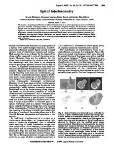
Fig. 7.
tion can play an appreciable role in forming for relatively small values of the angle ¯␣ and the displacement R, in particular for spiral beams. (III.a) Case of l ⬎ 0, ⬎ 0. This is illustrated by Fig. 7 on the example of the vortex-beam array [Fig. 7(a)] and the spiral beams [Fig. 7(b)] with N = 8, l = 1, and M = 6. In the range of positive values of the angle ¯␣ ⬎ 0, the array has the only critical point of the order Q = N − 共l + M兲 for R = 兩¯␣兩. It is this critical point that is responsible for a splash of the OAM. The specific OAM changes its value sharply from = Q = l + M = 7 to = Q = −关N − 共l + M兲兴 = −1. Then the OAM decreases droningly as the angle ¯␣ increases. In the range of negative values ¯␣ ⬎ 0, the OAM of the beam array experiences a number of splashes at the points R = Rcrit. A character of these splashes is welltraced on the example of a spiral beam OAM shown in Fig. 7(b). On the other hand, positions R = Rcrit of the critical points in the field are defined by the roots of polynomial (30), where the order of the critical points is equal to Q = N + l + M. However, the curve 共¯␣兲 shows that the positions of the maxima max do not coincide with those of critical points defined by polynomial (30). For example, 共1兲 the first root equals Rcrit = 0.5, whereas the first maximum 共1兲 of the curve 共¯␣兲 corresponds to Rmax ⬇ 0.73. For the sec共2兲 ond root, we have Rcrit ⬇ 0.955, while the maximum max is related to R共2兲 extr ⬇ 1.36. Discrepancies in the values Rcrit and Rmax grow as the displacement R increases. Moreover, a number of roots Rcrit and maxima Rmax differ. In our case, the number of roots is M = 6, whereas the num-
Evolution of a vortex-beam array (a) and a spiral beam (b) in the state {8, 1, 6}.
180
Fig. 8. −1其.
J. Opt. Soc. Am. A / Vol. 25, No. 1 / January 2008
Specific OAM 共¯␣兲 for a spiral beam in the state 兵9 , 2 ,
ber of maxima is K = 8. Nevertheless, the value of the OAM and the order of the critical point for the two first maxima coincide: = Q = N + l + M = 15. (III.b) Case l ⬎ 0, ⬍ 0. This case is presented by a spiral beam with parameters N = 9, l = 2, and M = −1, shown in Fig. 8. For the positive angle ¯␣, the spiral beam is in an unstable state with = Q = −关N − 共l + M兲兴 = −8. In accordance with the version (V.I) from Section 2, the critical points have the order Q = −关2N − 共l + M兲兴 = −17 at the point R = ¯␣ = 2. However, we observe a splash of the OAM up to extr = −17 at Rextr ⬇ 2.85. The competitive rotational processes smooth as a result of the critical point explosion. For a range of negative angles ¯␣ ⬍ 0, a spiral beam is in a stable state with = Q = l + M = 1 within the angles ¯␣ 苸 共0 , −2兲, then the OAM begins gradually to rise. (IV) Case of spiral beams with a zero OAM. Although the OAM of a vortex-beam array can vanish at isolated points 共R , ¯␣兲, spiral beams carry over, as a rule, a certain nonzero OAM. Nevertheless, there are some particular cases of disappearance of the OAM in structurally stable spiral beams within a certain range of their intrinsic parameters. First of all, it refers to the beams with the following parameters: (1) N = l + M and (2) l + M = 0. Figure 9 illustrates such a situation using the example of a spiral beam in the state 兵8 , 3 , −3其. The crucial point in this state disappears at the beam axis both for ¯␣ ⬎ 0 and ¯␣ ⬍ 0. Instead, there arises the central maximum encircled with a
Fig. 9.
Spiral beams with a zero OAM in the state 兵8 , 3 , −3其.
Izdebskaya et al.
net of identical optical vortices for the case ¯␣ ⬎ 0 or a net of topological dipoles for ¯␣ ⬍ 0. The angular momenta of individual beams are suppressed by the angular momentum connected with the off-axis geometry of the beam as a whole and the phase matching. Thus, the trait feature of the vortex-beam array is an indirect linkage between the order of a critical point Q and the value of a specific OAM . The interferential processes play a major role for the values 兩¯␣兩 , R ⬍ 1 so that the geometrical contribution of the individual beams to the OAM is suppressed. Splashes of the OAM = extr coincide with the order of critical points Q under the condition 兩¯␣兩 = R. When increasing the values 兩¯␣兩 , R ⬎ 1, the role of the array geometry becomes stronger, whereas the contribution of a critical point is smoothed out. The disappearance of the OAM = 0 at some points ¯␣ and R is associated with a state of unstable equilibrium among three competitive rotational movements, while vanishingly small magnitudes of the OAM ⬇ 0 within a whole range of values ¯␣ and R are conjugated with the disappearance of the central critical point from the array.
4. CONCLUSIONS We have considered a symmetric array of singular beams whose axes lay on the surface of a hyperboloid of revolution. Such a vortex-beam array is characterized by the number of beams N, the orbital number l connected with phase matching of individual beams, the topological charge M of each beam, the relative displacement R, and the relative angle ¯␣. A key characteristic of the beam array is a critical point of the order Q positioned at the array axis (a topological charge of a centered optical vortex). We revealed that the beam array turns into a typical spiral beam when the beam displacement R and the inclination angle 兩¯␣兩 are equal to each other. However, the equality R = 兩¯␣兩 can also corresponds to a delay of the critical point of the order Q into N single-charged vortices and a centered vortex with a topological charge equal to l + M. This means that the spiral beams bearing higher-order optical vortices are nongeneric ones. They can also be structurally unstable ones under certain conditions, since slight perturbations (random or determinate) of the intrinsic beam parameters that do not breaking the array symmetry entail a delay of their critical points. The array parameters l, M, and ¯␣ are associated with individual rotations of energy flux. Competition of such rotations defines a total characteristic of the beam array—an OAM. We revealed that the conditions of structural instability of spiral beams are accompanied by sharp splashes of the OAM. At the same time, the spiral beam with the state M = 0, N = 2兩l兩 can be referred to as a structurally stable one, since its specific OAM has no distinctive splashes via variations of the intrinsic parameters. We will show that such a spiral beam can be produced on the basis of light diffraction on a stack of dielectrical wedges [35,36] in a forthcoming next paper. Extreme values of the specific OAM are equal to the order of critical points if 兩¯␣兩 , R ⬍ 1. When R Ⰷ 兩¯␣兩 (or vice versa R Ⰶ 兩¯␣兩), the OAM increases (or decreases) linearly with a value R (or ¯␣).
Izdebskaya et al.
Vol. 25, No. 1 / January 2008 / J. Opt. Soc. Am. A
ACKNOWLEDGMENTS
20.
The authors thank E. G. Abramochkin and V. G. Volostnikov for a profitable discussion. Alexander Volyar thanks A. Desyatnikov for raising the question of a vortex beam with zero orbital angular momentum, which in fact inspired this work.
21. 22. 23.
REFERENCES 1. 2. 3.
4. 5. 6. 7. 8.
9. 10. 11. 12. 13. 14. 15. 16. 17. 18. 19.
M. S. Soskin and M. V. Vasnetsov, “Singular optics,” in Progress in Optics, E. Wolf, ed. (Elsevier North-Holland, 2001), Vol. 42, pp. 219–276. V. Vasnetsov and K. Staliunas, eds., Optical Vortices, Vol. 228 of Horizons of World Physics (Nova Science, 1999). V. Garces-Chavez, D. McGloin, M. D. Summers, A. Fernandez-Nieves, G. C. Spalding, G. Cristobal, and K. Dholakia, “The reconstruction of optical angular momentum after distortion in amplitude, phase and polarization,” J. Opt. A, Pure Appl. Opt. 6, S235–S238 (2004). J. Lin, X.-C. Yuan, X. Peng, and H. B. Niu, “Deterministic approach to the generation of modified helical beams for optical manipulations,” Opt. Express 13, 3862–3867 (2005). A. Vaziri, G. Weihs, and A. Zelinger, “Superpositions of the orbital angular momentum for applications in quantum experiments,” J. Opt. A, Pure Appl. Opt. 4, S47–S51 (2002). L. Allen, S. M. Barnet, and M. J. Padgett, Optical Angular Momentum (IOP, 2003). A. S. Desyatnikov, Yu. S. Kivshar, and L. Torner, “Optical vortices and vortex solutions,” in Progress in Optics, E. Wolf, ed. (Elsevier North-Holland, 2005), Vol. 47, pp. 1–45. C. Rockstuhl, A. A. Ivanovskyy, M. S. Soskin, M. G. Salt, H. P. Herzig, and R. Dändliker, “High-resolution experiment of phase singularities produced by computer-generated holograms,” Opt. Commun. 242, 163–169 (2004). L. E. Helseth, “Optical vortices in focal region,” Opt. Commun. 229, 85–91 (2004). M. V. Berry, “Optical vortices evolving from helicoidal integer and fractional phase steps,” J. Opt. A, Pure Appl. Opt. 6, 259–268 (2004). A. E. Siegman, Lasers (University Science, 1986). F. Gori, G. Gauttari, and C. Padovani, “Bessel–Gaussian beams,” Opt. Commun. 64, 491–495 (1987). A. P. Kiselev, “The localized light waves: paraxial and exact solution to the wave equation,” Opt. Spectrosc. 102, 697–717 (2007). J. C. Gutierrez-Vega and M. A. Bandress, “Helmholtz–Gauss waves,” J. Opt. Soc. Am. A 22, 289–298 (2005). M. Guizar-Sicairos and J. C. Gutierrez-Vega, “Generalized Helmholtz–Gauss beams and its transformation by paraxial optical system,” Opt. Lett. 31, 2912–2914 (2006). C. A. Alonzo, P. J. Rodrigo, and J. Glückstad, “Helicoconical optical beams: a product of helical and conical phase fronts,” Opt. Express 13, 1749–1760 (2005). E. G. Abramochkin and V. G. Volostnikov, “Generalized Gaussian beams,” J. Opt. A, Pure Appl. Opt. 6, S157–S161 (2004). V. V. Kotlyar, R. V. Skidanov, S. N. Khonina, and V. A. Soifer, “Hypergeometric modes,” Opt. Lett. 32, 742–744 (2007). I. Freund, “Critical point explosions in two-dimensional wave fields,” Opt. Commun. 159, 99–117 (1999).
24. 25. 26.
27. 28. 29. 30. 31. 32. 33. 34. 35. 36.
37. 38.
39.
40.
41. 42.
181
I. Freund, “Saddle point wave fields,” Opt. Commun. 163, 230–242 (1999). J. Courtial, R. Zambrini, M. R. Dennis, and M. Vasnetsov, “Angular momentum of optical vortex array,” Opt. Express 14, 938–949 (2006). B. Lü and H. Ma, “Beam combination of radial laser array: Hermite–Gaussian model,” Opt. Commun. 178, 395–403 (2000). I. D. Maleev and G. A. Swartzlander, “Composite optical vortices,” J. Opt. Soc. Am. B 20, 1169–1176 (2003). Z. Bouchal, “Controlled spatial shaping of nondiffracting patterns and arrays,” Opt. Lett. 27, 1376–1378 (2002). Ya. Cai and O. Lin, “Decentered elliptical Gaussian beams,” Appl. Opt. 41, 4336–4340 (2002). C.-S. Cuo, Y. Zhang, Y.-J. Han, J.-P. Ding, and H.-T. Wang, “Generation of optical vortices with arbitrary shape and array via helical phase spatial filtering,” Opt. Commun. 259, 449–454 (2006). Z. Bouchal and J. Courtial, “The connection of singular and nondiffractive optics,” J. Opt. A, Pure Appl. Opt. 6, S184–S188 (2004). S. Vyas and P. Senthsilkumaran, “Interferometric vortex array generator,” Appl. Opt. 46, 2893–2898 (2007). E. G. Abramochkin and V. G. Volostnikov, “Spiral light beams,” Phys. Usp. 174, 1273–1300 (2004), http:// www.ufn.ru/ufn04/ufn04គ12/ufn0412a.pdf. E. G. Abramochkin and V. G. Volostnikov, “Spiral-type beams: optical and quantum aspects,” Opt. Commun. 125, 302–323 (1996). E. G. Abramochkin and V. G. Volostnikov, “Spiral-type beams,” Opt. Commun. 102, 336–350 (1993). T. Poston and I. Stewart, Catastrophe Theory and Its Applications (Pitman, 1978). M. V. Berry, “Catastrophe optics: morphologies of caustics and their diffraction patterns,” in Progress in Optics XVIII, E. Wolf, ed. (Elsevier North-Holland, 1980), pp. 257–346. I. Freund and N. Shvartsman, “Wave-field phase singularities: the sign principle,” Phys. Rev. Lett. 50, 5164–5172 (1994). Ya. Izdebskaya, V. Shvedov, and A. Volyar, “Generation of higher-order optical vortices by a dielectric wedge,” Opt. Lett. 30, 2472–2474 (2005). X.-C. Yuan, B. P. S. Ahluwalia, S. H. Tao, W. C. Cheong, L.-S. Zhang, J. Lin, J. Bu, and R. E. Burge, “Wavelengthscalable micro-fabricated wedge for generation of optical vortex beam in optical manipulation,” Appl. Phys. B: Lasers Opt. 86, 209–213 (2007). M. Abramowitz and I. Stegun Handbook of Mathematical Functions (Dover, 1970). A. Volyar, V. Shvedov, Ya. Izdebskaya, T. Fadeyeva, and A. Rubass, “Structure and orbital angular momentum of singular array of Gaussian beams,” Ukr. J. Phys. Opt. 3, 79–88 (2006), www.ifo.lviv.ua. K. O’Holleran, M. J. Padgett, and M. R. Dennis, “Topology of optical vortex lines formed by the interference of three, four and five plane waves,” Opt. Express 14, 3039–3044 (2006). Ya. Izdebskaya, T. Fadeyeva, V. Shvedov, and A. Volyar, “Vortex-bearing array of singular beams with very high orbital angular momentum,” Opt. Lett. 31, 2523–2525 (2006). M. Berry, “Paraxial beams of spinning light,” Proc. SPIE 3487, 6–11 (1998). A. P. Prudnikov, Yu. A. Brychkov, and O. I. Marichev, Integrals and Series, Volume 2: Special Functions (Gordon and Breach, 1986).