Proc. 2nd IEEE Benelux Signal Processing Symposium (SPS-2000), Hilvarenbeek, The Netherlands, March 23-24, 2000
SYNCHRONOUS MC-CDMA IN DISPERSIVE, MOBILE RAYLEIGH CHANNELS. Jean-Paul Linnartz Philips Research, Nat.Lab. WY 8, 5656 AA Eindhoven, The Netherlands fax: +31 40 2744660,
[email protected] http://wireless.per.nl Time variations of the mobile radio channel cause InterCarrier Interference (ICI) to Orthogonal Frequency Division Multiplexing (OFDM) and Multi-Carrier CDMA (MCCDMA) radio links. This paper evaluates the effect of Doppler and delay spreads on the performance of an MC-CDMA receiver. An MMSE receiver is analyzed for MC-CDMA transmission over a mobile channel with Doppler. A simplified, pseudo MMSE receiver is proposed that does not need to perform real-time inversion of a large matrix. It performance is shown to be better than for (uncoded) OFDM.
waves, each with it own angle of arrival and corresponding Doppler frequency offset. Only in the special case that the delay spread among these multiple reflections is negligible compared to inverse of the total transmit bandwidth (so all subcarriers see the same channel fading), the Doppler spread can be shown to be equivalent to a common frequency offset. The effect of Doppler spread on OFDM was previously addressed, e.g. in [3] and [4].
S/P N
1.
B
Summary
Orthogonal Frequency Division Multiplexing (OFDM) is a modulation method designed in the 1960’s and 1970’s in which multiple user symbols are transmitted in parallel using different subcarriers. These subcarriers have overlapping spectra, but their signal waveforms are specifically chosen to be orthogonal. Compared to modulation methods such as BPSK, QPSK or MSK, OFDM transmits symbols, which have relatively long time duration, but a narrow bandwidth. Mostly, OFDM systems are designed such that each subcarrier is small enough in bandwidth to experience frequency-flat fading. This also ensures that the subcarriers remain orthogonal when received over a (moderately) frequency selective but time-invariant channel. If the OFDM signal is received over such a channel, each subcarrier experiences a different attenuation. In Coded-OFDM, errors which are most likely to occur on subcarriers which are most severely attenuated, are repaired by error correction codes. To this end, the redundancy in the error correction code is typically spread over many different subcarriers. While its robustness against frequency selectivity is seen as an advantage of OFDM, any time-varying character of the channel is known to pose limits to the system performance. Time variations are known to corrupt the orthogonality of the OFDM subcarrier waveforms [1]. In such case, InterCarrier Interference (ICI) occurs because signal components from one subcarrier cause interference to other, mostly to neighboring subcarriers. The effect of ICI has been analyzed for carrier frequency errors and Wiener phase noise in [2]. In this paper, we model mobile radio propagation to study the effect of user mobility. In a Rayleigh fading channel, Doppler spreading caused by the mobile channel cannot be compensated (or modeled) by a common frequency correction for all subcarriers. Because of multipath propagation, the receiver sees a large collection of incoming
S00-1
S/P N
Code Matrix C
FFT
N
I-FFT
N
P/S
A N
Y
Weigh N Matrix A W
I-Code Matrix C-1
N
P/S
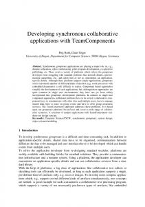
Figure 1: OFDM and MC-CDMA Transmit System and MMSE Receiver architecture This paper reviews the classic OFDM modulation, and introduces new results for a CDMA-type of transmission which is an extension of the basic OFDM principle. At PIMRC 1993, this form of Orthogonal Multi-Carrier CDMA was proposed [5], [8]. Basically it applies an OFDM-type of transmission to a multiuser synchronous DS-CDMA signal. In DS-CDMA, each user bit is transmitted as many sequential chips, each of which is of short duration, thus of wide bandwidth. In contract to this in MCCDMA, chips are long in time duration, but narrow in bandwidth. Multiple chips are not-sequential, but transmitted in parallel on different subcarriers. Several other MultiCarrier CDMA schemes have also been proposed, but we restrict our analysis here the above one. The outline of the paper is as follows: Section 2 combines the OFDM transmit model with models by Clarke and Aulin for multipath channels. It gives expressions for the ICI under Doppler spreading. The effect of a Rayleigh Doppler spread on the BER is calculated for a conventional OFDM receiver. Section 3 addresses MC-CDMA and derives receiver settings for an MMSE receiver and a channel with delay and Doppler spread. A simplification is proposed which mitigates the need for accurate channel estimation and adaptive filtering. Its performance is analyzed. Numerical and simulation results are in Section 5.
Proc. 2nd IEEE Benelux Signal Processing Symposium (SPS-2000), Hilvarenbeek, The Netherlands, March 23-24, 2000
2.
Channel model
B1 =
10
10
∑
i =0
ù sinc n − m + i 2 ù s
0
-1
Power, Variance of ICI
P1
10
10
i
10
P2
P3
-2
-3
-4
0
0.5
1
1.5
2
2.5
3
3.5
4
4.5
5
Normalized Doppler [fm/fsub]
Figure 2: Received power P0, and the variances P1, P2, and P2 of the ICI versus the normalized Doppler spread λ for pT = 1.
3.
Receiver model
The Minimum Mean-Square Error Estimate of the user data is equal to the conditional expectation E[B|Y] = E[C−1A|Y] = C −1 E[A|Y]. Let the estimate A be a linear combination of Y, namely A = WY. The optimum choice of matrix W follows from the orthogonality principle that the estimation error is uncorrelated with the received data, viz., E[(A − A)YH] = 0N with 0N the all-zero matrix of size N by N. Thus we arrive at W = E[AYH] RYY−1, for the optimum estimation matrix. Here Y = HA + N, where channel matrix H has the components Hnm = Tsβnm. So,
exp{− j(ù c + ù i + nù s )Ti − 12 jù i Ts + jπ (n − m)}
The OFDM frame duration Ts is related to the intercarrier spacing fs = ωs/(2π), according to ωsTs = 2π. For uniform angles of arrivals of reflected waves one can show that the variance of the ICI signal spilled from transmit subcarrier n into received subcarrier m = n + ∆ equals [3] f sinc 2 ∆ + ∆ x dx 1 f P s P∆ = E ch β n +∆ ,n β * n + ∆ ,n = T ∫ 8π −1 1 − x2
(
γ +1
P0
The Wide Sense Stationary Uncorrelated Scattering multipath channel is modeled as a collection of Iw reflected waves. Each wave has its particular Doppler frequency offset ωi, path delay Ti and amplitude Di, each of which is assumed to be constant. Vector Y describes the outputs of the FFT at the receiver, with Y = [y0, y1, .., yN−1]T, with ym = Σnanβm,nTs where βm,n is the ‘transfer’ for a signal transmitted at subcarrier n and received at subcarrier m, I w −1 D
γ π 2 f ∆2 6 f s2
For OFDM, vector A of length N carries a ‘frame’ of user data, with A = [a0, a1, … aN−1]T, where the elements an are user symbols. In MC-CDMA, A = CB, where C is an N by N code matrix and B = [b0, b1, … bN−1]T represents a frame of user data. The kth column of C represents the spreading code of user data stream k, and will be denoted as (ck[0], .. ck[N − 1])T. We use C = N−1/2 WHN where WHN is the Walsh-Hadamard matrix of size N by N. In that case, C = C−1 = CH, so C C = IN with IN the N by N identity matrix. For ease of analysis, we normalize the modulation depth as E bibj* = δij, or equivalently EBBH = IN. Then E[AAH] = EC[BBH]CH = CCH = IN.
β m,n =
1 1 − 2 2
E[AYH] = E[A[HA]H] + E[ANH] = E[AAHHH] = C E[BBHCHHH] = HH.
)
where f∆ is the maximum Doppler shift and PT the local mean received power, per subcarrier (see Fig. 2).
Also, RYY, the covariance matrix of Y, becomes RYY = EYYH = H E[AAH] HH + ENNH = HHH + N0 TsIN..
For engineering applications with small Doppler spreads, a rule of thumb can be derived. It appeared necessary to consider higher order tiers of neighboring subcarriers, but it was permissible to use a first-order approximation for the sinc. For arguments near zero, we take sinc(f fs−1) ≈ 1, so we find that P0 ≈ PT. For ∆ = k (and for f