change across views, a visually compelling rendering of hidden ar- eas is achieved without ... Figure 1: By using a 2D projective invariant to transfer image data between cameras, our ..... SIFT-based matching is free from drift, we were able to run for sev- eral hours without ... Pfinder: Real- time tracking of the human body.
Peter Barnum, Yaser Ajmal Sheikh, Ankur Datta and Takeo Kanade, “Dynamic Seethroughs: Synthesizing Hidden Views of Moving Objects,” International Symposium on Mixed and Augmented Reality, October 2009.
Dynamic Seethroughs: Synthesizing Hidden Views of Moving Objects Peter Barnum
Yaser Sheikh
Ankur Datta
Takeo Kanade ∗
Carnegie Mellon University Robotics Institute Pittsburgh, PA, USA
A BSTRACT This paper presents a method to create an illusion of seeing moving objects through occluding surfaces in a video. This illusion is achieved by transferring information from a camera viewing the occluded area. In typical view interpolation approaches for 3D scenes, some form of correspondence across views is required. For occluded areas, establishing direct correspondence is impossible as information is missing in one of the views. Instead, we use a 2D projective invariant to capture information about occluded objects (which may be moving). Since invariants are quantities that do not change across views, a visually compelling rendering of hidden areas is achieved without the need for explicit correspondences. A piece-wise planar model of the scene allows the entire rendering process to take place without any 3D reconstruction, while still producing visual parallax. Because of the simplicity and robustness of the 2D invariant, we are able to transfer both static backgrounds and moving objects in real time. A complete working system has been implemented that runs live at 5Hz. Applications for this technology include the ability to look through corners at tight intersections for automobile safety, concurrent visualization of a surveillance camera network, and monitoring systems for patients/elderly/children. Keywords: personal MR/AR information systems, industrial and military MR/AR applications, real-time rendering, vision-based registration and tracking, object overlay and spatial layout techniques, performance issues [real-time approaches] Index Terms: H.5.1 [Information Interfaces and Presentation]: Multimedia Information Systems—Artificial, Augmented, and Virtual Realities 1
I NTRODUCTION
There is a proliferation of cameras in our urban space, with millions of camera-enabled cellphones, security cameras, and webcams. Often areas of a scene occluded in one view can be clearly viewed by a different camera. If visual information about the occluded area can be transferred from the view in which it is visible to the view in which it is occluded, an interactive image can be rendered where users can actively explore occluded areas. There are many potential real-world applications for such a technology including the ability to look through corners at tight intersections for automobiles, concurrent visualization of a surveillance camera network, and monitoring systems for patients/elderly/children. The central idea that allows us to transfer information from the hidden view to the observed view without explicit estimation of correspondence is the expression of depth in terms of a projective invariant. As it is invariant across cameras, the quantity estimated in the hidden view can be directly used in the source view, without the need for 3D models or correspondence across cameras. Because this quantity is constrained by an implicit 3D approximation of the scene, both static and dynamic objects can be directly transfered ∗ e-mails:
{pbarnum,yaser,ankurd,tk}@cs.cmu.edu
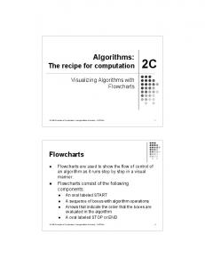
Figure 1: By using a 2D projective invariant to transfer image data between cameras, our system can render views of dynamic occluded objects in real time. As shown in these simulated multiple exposure images, our method creates videos that are accurate and convincing.
from a reference camera viewing the occluded area to the source camera (Figure 1). The rendered view preserves the fidelity of image information, even in the presence of inevitable localization errors. In addition, the use of 2D projective quantities reduces the computational complexity of the entire process. We have implemented a live system that runs at 5Hz, producing a visually compelling synthesis of hidden views in a moving source camera. 2 R ELATED W ORK View interpolation methods like [2], [13], and [11], used detailed disparity, correspondence, or z-buffers. Data-intensive approaches, like the Movie-Map [10] and Lumigraph [4] approaches, side-step the problem of correspondence by using a large number of images to render new views of a scene. Another approach to using a large number of images is the work on Photo-tourism, described in [14] And if detailed geometric models are available, then methods like [3] and [9] can be used to render new views of scenes. Augmented reality also can involve view interpolation. If partial 3D models of landmarks are available, Kameda et al. [7] demonstrate how to synthesize a see-through composite image from multiple surveillance cameras. Moving objects are warped based with the same homography as nearby walls, although they discuss that approximating objects as 2D planes in 3D space as in [8], [6], and [12] could increase accuracy within the same framework. 3 OVERVIEW Our system consists of a source camera that may be moving, and a stationary reference camera viewing an area occluded in the source view. The input into the system is video from the two cameras, and the output is a video rendered from the source view where the user can see through the occluding surface. 3.1 Scene Model The reference camera is a stationary camera which views the object while it is occluded by the side plane ΠS . The vanishing line of the back plane ΠB , a vanishing point, and the segmentation of the support of ΠB in the image are manually pre-calibrated. The source camera is a moving camera that sees the side plane, and parts of the ground and the back plane, but the object may be completely occluded by the side plane in this case. Finally, a transfer camera is an stationary camera that is placed near the expected location of the source camera to aid in matching the back plane. The user outlines a mask and optionally a line drawing on ΠS , which is warped to the
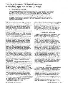
Reference View
Popped-In
Transported
Popped-out
Synthesized
Figure 2: Transferring information from the reference view to the source view. (The change between these images is most noticeable at the man’s feet and arms.) From left to right: (1) The object and back plane in the original reference image; (2) The object popped-in by applying a homology using a characteristic ratio µ; (3) The popped-in object and plane transported by applying a homography; (4) The object popped-out by applying another homology using the same characteristic ratio µ; (5) The information from the reference plane is inserted to the source view. Occluding Surface
Back Plane
+ Source View
1. ar : The vanishing line (axis of the parallel planes ΠB and Πo ) of the back plane ΠB in the reference view 2. vr : The vanishing point in the direction of the normal of ΠB 3. lrb∩g : the line of intersection between ΠB and ΠG
= Reference View
Synthesized Hidden View
Figure 3: Rendering Seethroughs. In our setup, dynamic objects which are occluded in a moving source camera are rendered by transferring information from a reference camera to the source view.
source view during runtime. A view of the occluded object is not required in the transfer camera. Throughout this paper, subscripts identify planes and superscripts identify cameras. 3.2 View Transfer: Pop-in, Transport, Pop-out The background facade is treated as a plane and is partially visible in both source and reference view. During runtime, homographies are estimated that transform the background facade and ground plane from the reference to the source view. The occluded object is transported from the reference camera to the source camera indirectly via this background homography in three steps: 1. Pop-in: Objects in the reference view are projected onto the back plane ΠB using a homology, represented by the 3 × 3 matrix Hin . 2. Transport: The homography HBr→s for ΠB is used to transport data from the reference to the source image. 3. Pop-out: The transported object is then popped-out once again using a homology, Hout . The complete transformation that transfers the object from the reference view to the source view is therefore, Hor→s = Hout HBr→s Hin .
(1)
Figure 2 illustrates the steps for transferring the object from the reference image to the source image. The entire procedure deals with two dimensional quantities, and as a result, the process is fast, stable, and preserves the fidelity of image information. µo is a scalar called the characteristic ratio of a homology. The fact that it is a projective invariant allows us to compute the pop-out homology even when there is no information about the object in the source view. 4 T HE R EFERENCE C AMERA : O BJECT P OP - IN The reference camera sees the object that is occluded in the source camera. In this view, the distance of the object from the back plane is encoded in the projective invariant µo . To compute the invariant and to pop-in the object, we require the reference view to be partially calibrated by specifying:
4. SrB : the binary mask image that specifies the support of the back plane ΠB in the reference view 5. SrG : the binary mask image that specifies the support of the ground plane ΠB in the reference view The vanishing line of the back plane ar and the vanishing point can be computed in many ways [5], such as by marking the image location of points on two lines known to be parallel in the world. To obtain the silhouette of the object during runtime, Sro , we perform background subtraction in the reference view with a per-pixel trivariate Gaussian model, similar to Wren et al. [16]. With these quantities pre-calibrated, the transfer of the object from source to reference view begins by popping-in the object using a homology. 4.1 What is a Homology? The object is approximated by a plane parallel to the backplane ΠB . There is special type of 2D homography called a homology that can transform image points between parallel planes. A homology H has an axis line a and vertex point v and is computed as vaT H = I + (µ − 1) T . (2) v a In this equation, I is a 3 × 3 identity matrix and µ is a scalar called the characteristic ratio, which encodes the distance between the parallel plane in 3D. µ is of fundamental importance, because the cross-ratio is a projective invariant — when it is measured across different views, it remains the same quantity. Thus, even though we do not have any information about the object distance to the plane in the source view, the invariance of µ across views encodes this information and can be used directly without any measurement. 4.2 Pop-in To compute the pop-in homology Hin , we begin by observing that one object point is on the ground, which we will call xro . As illustrated in Figure 4, Hin will project any point on the object to a point on the back plane, therefore, xrB = Hin xro . (3) r r The line that connects xo and the pre-calibrated vertex v is l = xro × vr . Using the pre-calibrated line of intersection lrB∩G , we find that xrB = l×lrB∩G . As shown in Appendix 7 of [5], the characteristic invariant for warping the object to the backplane µo is computed from the cross ratio of the four points {xra , vr , xrB , xro }. This allows us to find Hin via Equation 2. 5 R EFERENCE TO S OURCE : O BJECT T RANSPORT The next step is to transport image information of the background plane from the reference view to the source view. As the object has been popped-in, we are simultaneously transporting the object as well. To aid matching, one or more transfer images or transfer
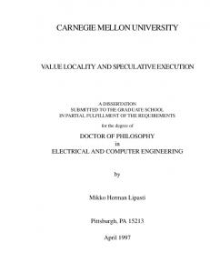
ar
vr r
l B∩G x rB
as
vs s
l B∩G
x or
x ar
x sB
xso
xsa
Figure 4: The characteristic ratio µo , that transforms xro to xrB in the reference image, is the cross ratio of the four points {xra , vr , xrB , xro }. The cross ratio is a projective invariant — it remains the same across the two views. As a result, µ is also the characteristic ratio that takes xso to xsB in the source image. (Note: the axes ar and as have been brought artificially close to the images to aid in visualization.)
cameras are used in locations near the path of the source camera motion. For each transfer image, we calibrate the homographies from the reference camera to source camera for the back plane Hr→t B and the ground plane Hr→t G . With the small-baseline match given r→s by Ht→s B computed by SIFT and RANSAC, the total warping HB r→t is a matrix multiplication with the pre-calibrated HB , r→t Hr→s = Ht→s (4) B B HB . In addition to the back and ground planes, the transfer side plane ΠS may not be visible in the reference view, but it is transformed from a transfer view via the same feature matching and homography t computation, yielding Ht→s S . And similarly to [1], a binary mask SS or line drawing specified on the transfer image can be warped to the source, to give the impression of looking through a window on the occluding wall (as shown in Figure 5) .
6 T HE S OURCE C AMERA : O BJECT P OP - OUT The source camera is a moving camera that contains the view of the occluding surface we want to see through. The key challenge in rendering the seethrough view is transferring the occluding object in the reference view to the source view without any measurable object-specific information in the source view. We present a solution to this problem in this section and describe how to render the final view. 6.1 Pop-Out Once the transport homography HBr→s and the pop-in homology Hin are known, we need to estimate the final pop-out homology Hout to render the view of the occluded object in the source image. In order to construct the pop-out homology, we need to know the axis as and vertex vs and the value of the characteristic ratio. Since the axis lies on the back plane, it can be transformed to the source camera via the back plane transfer homography, −T r as = (Hr→s a. (5) B ) r→s could be comIf the ground plane is well textured, then HG puted directly to find vs . However in many scenes, the ground plane is textureless and difficult to track. But since the side and ground planes are perpendicular in most urban settings, both have the same vanishing point. Therefore, the vanishing point in the source image can also be computed as,
Figure 5: A strong cue for observers is cross-over accuracy: does the object appear to accurately cross over? Incorrect alignment would cause obvious errors in the seethrough. r→t r vs = Ht→s S HG v .
(6)
The characteristic ratio µo is an invariant across views, therefore popping-out is the inverse of the popping-in, � vs (as )T � 1 . (7) Hout = I + −1 µo (vs )T as The end-to-end homography that transports the object from the reference to the source camera is then computed via Equation 1. 6.2
View Rendering
To render the final view, the segmented object, back plane and ground plane in the reference view are transformed to fill in the occluded area in the source view. For all pixels x inside the reference background mask but not in the reference object mask, r r r Hs→r B x ∈ SB −SB ∩So , the view image is rendered as an alpha blend of the source and mean background, αIsource (x) + (1 − α)Imean (w(x|Hs→r B )). For all pixels x inside the reference object mask, view image is rendered as,
Hs→r o x
αIsource (x) + (1 − α)Ireference (w(x|Hs→r o )). 7
(8) ∈
Sro ,
the (9)
R ESULTS
We tested our view synthesis method on several different indoor and outdoor scenes. There are a variety of ways to quantify the perceptual accuracy of an augmented reality system, such as correct depth [15]. We found that there four main requirements for a result to be visually plausible. The first and simplest is that the objects transferred from the occluded view should have reasonable sizes, positions, and skews. Second, as the source camera moves, the objects must show proper parallax when on the occluded side, otherwise they appear to simply be pasted to the wall. Third, an object must pass seamlessly across the occlusion boundary, as shown in Figure 5. Fourth, a moving object should appear to keep the same smooth trajectory on both sides the boundary, which is shown in Figure 1. Our algorithm is able to perform even when both the source camera and objects in the scene are moving. A live system running at 5hz was setup demonstrating how vehicle drivers could see around corners by receiving data from cameras placed at intersections. The full setup is shown in Figure 7. Participants could move the source cameras and see the synthesized view on a large television. Since
DISPLAY
OBJECT
REFERENCE CAMERA
SOURCE CAMERA
(a)
Figure 7: Wide view of the setup for the realtime system. The reference camera captures a view of the object when it is occluded by the divided wall. The final seethrough was shown on the display as shown in the bottom figure.
(b) Figure 6: Two example sequences demonstrating applications of seethroughs. (a) Traffic intersection seethrough. The source camera, mounted on a car, moves towards an intersection. Using the reference camera, the car occluded by the wall becomes visible. (b) Concurrent visualization. Seethroughs allow users to simultaneously monitor two video sequences in context of one another. A person runs in a straight line from the right, then drops to the ground and makes a snow angel behind the stone wall — an action occluded in the source view.
SIFT-based matching is free from drift, we were able to run for several hours without re-initialization. We used two standard DV camcorders that captured 720x480 interlaced images at 30Hz. Results from the live system are shown in Figures 5 and 7. One applications of the proposed method is shown in Figure 6 (a). A sequence is taken from a moving vehicle, as it approaches an intersection. The seethrough in this application improve driver safety, allowing the driver to ensure there is no incoming traffic as he or she makes a turn around a corner. In Figure 6(b), two video streams are visualized concurrently. Seethroughs allow both videos to be seen simultaneously. 8
D ISCUSSION
AND
F UTURE W ORK
We present a new image-based technique to render visually compelling seethroughs of occluded areas in a video. The source camera in which the object is occluded may be moving, and the occluded object itself may be moving too. By approximating the scene as piece-wise planar in 3D, the entire process takes place using 2D quantities only, and no explicit 3D reconstruction is required. As a result, the approach is fast, robust, and better preserves the fidelity of image information. For future work, if the calibration is made fully automatic, then the reference camera could move as well. This would facilitate the creation of an ad hoc network where different mobile users would share image information automatically as they moved about the scene.
ACKNOWLEDGEMENTS This research was supported by a grant from DENSO CORPORATION. R EFERENCES [1] B. Avery, C. Sandor, and B. H. Thomas. Improving spatial perception for augmented reality x-ray vision. In Virtual Reality, 2009. [2] E. Chen and L. Williams. View interpolation for image synthesis. In SIGGRAPH. ACM, 1993. [3] P. E. Debevec, C. J. Taylor, and J. Malik. Modeling and rendering architecture from photographs: A hybrid geometry- and image-based approach. In SIGGRAPH. ACM, 1996. [4] S. J. Gortler, R. Grzeszczuk, R. Szeliski, and M. F. Cohen. The lumigraph. In SIGGRAPH. ACM, 1996. [5] R. Hartley and A. Zisserman. Multiple view geometry in computer vision. In Cambridge University Press, 2003. [6] E. Ichihara, H. Takao, and Y. Ohta. Naviview: Birds-eye view for highway drivers using roadside cameras. In Multimedia Computing and Systems, 1999. [7] Y. Kameda, T. Takemasa, and Y. Ohta. Outdoor see-through vision utilizing surveillance cameras. In ISMAR, 2004. [8] T. Koyama, I. Kitahara, and Y. Ohta. Live mixed-reality 3D video in soccer stadium. In ISMAR, 2003. [9] D. Liebowitz, A. Criminisi, and A. Zisserman. Creating architectural models from images. In Eurographics, 1999. [10] A. Lippman. Movie maps: An application of the optical videodisc to computer graphics. In SIGGRAPH. ACM, 1980. [11] L. McMillan and G. Bishop. Plenoptic modeling: An image-based rendering system. In SIGGRAPH. ACM, 1995. [12] I. O. Sebe, J. Hu, S. You, and U. Neumann. 3D video surveillance with augmented virtual environments. In IWVS, 2003. [13] S. Seitz and C. Dyer. View morphing. In SIGGRAPH. ACM, 1996. [14] N. Snavely, S. Seitz, and R. Szeliski. Photo tourism: exploring photo collections in 3D. In SIGGRAPH. ACM, 2005. [15] J. E. Swan, M. A. Livingston, H. S. Smallman, D. Brown, Y. Baillot, J. L. Gabbard, and D. Hix. A perceptual matching technique for depth judgments in optical, see-through augmented reality. In Virtual Reality, 2006. [16] C. Wren, A. Azarbayejani, T. Darrell, and A. Pentland. Pfinder: Realtime tracking of the human body. In IEEE Transactions on Pattern Analysis and Machine Intelligence. IEEE, 1997.